EP1595641B1 - Dispositif de serrage avec mandrin et palette fixé de façon amovible sur le mandrin. - Google Patents
Dispositif de serrage avec mandrin et palette fixé de façon amovible sur le mandrin. Download PDFInfo
- Publication number
- EP1595641B1 EP1595641B1 EP05405228A EP05405228A EP1595641B1 EP 1595641 B1 EP1595641 B1 EP 1595641B1 EP 05405228 A EP05405228 A EP 05405228A EP 05405228 A EP05405228 A EP 05405228A EP 1595641 B1 EP1595641 B1 EP 1595641B1
- Authority
- EP
- European Patent Office
- Prior art keywords
- centring
- chuck
- clamping
- pallet
- assembly according
- Prior art date
- Legal status (The legal status is an assumption and is not a legal conclusion. Google has not performed a legal analysis and makes no representation as to the accuracy of the status listed.)
- Expired - Lifetime
Links
- 240000006240 Linum usitatissimum Species 0.000 description 1
- 230000001419 dependent effect Effects 0.000 description 1
- 238000011161 development Methods 0.000 description 1
- 230000018109 developmental process Effects 0.000 description 1
- 230000000149 penetrating effect Effects 0.000 description 1
Images


Classifications
-
- B—PERFORMING OPERATIONS; TRANSPORTING
- B23—MACHINE TOOLS; METAL-WORKING NOT OTHERWISE PROVIDED FOR
- B23B—TURNING; BORING
- B23B31/00—Chucks; Expansion mandrels; Adaptations thereof for remote control
- B23B31/02—Chucks
- B23B31/10—Chucks characterised by the retaining or gripping devices or their immediate operating means
- B23B31/12—Chucks with simultaneously-acting jaws, whether or not also individually adjustable
-
- H—ELECTRICITY
- H05—ELECTRIC TECHNIQUES NOT OTHERWISE PROVIDED FOR
- H05B—ELECTRIC HEATING; ELECTRIC LIGHT SOURCES NOT OTHERWISE PROVIDED FOR; CIRCUIT ARRANGEMENTS FOR ELECTRIC LIGHT SOURCES, IN GENERAL
- H05B41/00—Circuit arrangements or apparatus for igniting or operating discharge lamps
- H05B41/14—Circuit arrangements
- H05B41/36—Controlling
- H05B41/38—Controlling the intensity of light
- H05B41/39—Controlling the intensity of light continuously
- H05B41/392—Controlling the intensity of light continuously using semiconductor devices, e.g. thyristor
- H05B41/3921—Controlling the intensity of light continuously using semiconductor devices, e.g. thyristor with possibility of light intensity variations
-
- B—PERFORMING OPERATIONS; TRANSPORTING
- B23—MACHINE TOOLS; METAL-WORKING NOT OTHERWISE PROVIDED FOR
- B23B—TURNING; BORING
- B23B31/00—Chucks; Expansion mandrels; Adaptations thereof for remote control
- B23B31/02—Chucks
- B23B31/10—Chucks characterised by the retaining or gripping devices or their immediate operating means
- B23B31/103—Retention by pivotal elements, e.g. catches, pawls
-
- B—PERFORMING OPERATIONS; TRANSPORTING
- B23—MACHINE TOOLS; METAL-WORKING NOT OTHERWISE PROVIDED FOR
- B23H—WORKING OF METAL BY THE ACTION OF A HIGH CONCENTRATION OF ELECTRIC CURRENT ON A WORKPIECE USING AN ELECTRODE WHICH TAKES THE PLACE OF A TOOL; SUCH WORKING COMBINED WITH OTHER FORMS OF WORKING OF METAL
- B23H7/00—Processes or apparatus applicable to both electrical discharge machining and electrochemical machining
- B23H7/26—Apparatus for moving or positioning electrode relatively to workpiece; Mounting of electrode
-
- B—PERFORMING OPERATIONS; TRANSPORTING
- B23—MACHINE TOOLS; METAL-WORKING NOT OTHERWISE PROVIDED FOR
- B23Q—DETAILS, COMPONENTS, OR ACCESSORIES FOR MACHINE TOOLS, e.g. ARRANGEMENTS FOR COPYING OR CONTROLLING; MACHINE TOOLS IN GENERAL CHARACTERISED BY THE CONSTRUCTION OF PARTICULAR DETAILS OR COMPONENTS; COMBINATIONS OR ASSOCIATIONS OF METAL-WORKING MACHINES, NOT DIRECTED TO A PARTICULAR RESULT
- B23Q1/00—Members which are comprised in the general build-up of a form of machine, particularly relatively large fixed members
- B23Q1/0063—Connecting non-slidable parts of machine tools to each other
- B23Q1/0072—Connecting non-slidable parts of machine tools to each other using a clamping opening for receiving an insertion bolt or nipple
-
- H—ELECTRICITY
- H05—ELECTRIC TECHNIQUES NOT OTHERWISE PROVIDED FOR
- H05B—ELECTRIC HEATING; ELECTRIC LIGHT SOURCES NOT OTHERWISE PROVIDED FOR; CIRCUIT ARRANGEMENTS FOR ELECTRIC LIGHT SOURCES, IN GENERAL
- H05B41/00—Circuit arrangements or apparatus for igniting or operating discharge lamps
- H05B41/14—Circuit arrangements
- H05B41/26—Circuit arrangements in which the lamp is fed by power derived from DC by means of a converter, e.g. by high-voltage DC
- H05B41/28—Circuit arrangements in which the lamp is fed by power derived from DC by means of a converter, e.g. by high-voltage DC using static converters
- H05B41/295—Circuit arrangements in which the lamp is fed by power derived from DC by means of a converter, e.g. by high-voltage DC using static converters with semiconductor devices and specially adapted for lamps with preheating electrodes, e.g. for fluorescent lamps
-
- B—PERFORMING OPERATIONS; TRANSPORTING
- B23—MACHINE TOOLS; METAL-WORKING NOT OTHERWISE PROVIDED FOR
- B23B—TURNING; BORING
- B23B2270/00—Details of turning, boring or drilling machines, processes or tools not otherwise provided for
- B23B2270/12—Centering of two components relative to one another
-
- B—PERFORMING OPERATIONS; TRANSPORTING
- B23—MACHINE TOOLS; METAL-WORKING NOT OTHERWISE PROVIDED FOR
- B23B—TURNING; BORING
- B23B31/00—Chucks; Expansion mandrels; Adaptations thereof for remote control
- B23B31/001—Protection against entering of chips or dust
-
- Y—GENERAL TAGGING OF NEW TECHNOLOGICAL DEVELOPMENTS; GENERAL TAGGING OF CROSS-SECTIONAL TECHNOLOGIES SPANNING OVER SEVERAL SECTIONS OF THE IPC; TECHNICAL SUBJECTS COVERED BY FORMER USPC CROSS-REFERENCE ART COLLECTIONS [XRACs] AND DIGESTS
- Y10—TECHNICAL SUBJECTS COVERED BY FORMER USPC
- Y10T—TECHNICAL SUBJECTS COVERED BY FORMER US CLASSIFICATION
- Y10T279/00—Chucks or sockets
- Y10T279/19—Radially reciprocating jaws
- Y10T279/1953—Toggle actuated
-
- Y—GENERAL TAGGING OF NEW TECHNOLOGICAL DEVELOPMENTS; GENERAL TAGGING OF CROSS-SECTIONAL TECHNOLOGIES SPANNING OVER SEVERAL SECTIONS OF THE IPC; TECHNICAL SUBJECTS COVERED BY FORMER USPC CROSS-REFERENCE ART COLLECTIONS [XRACs] AND DIGESTS
- Y10—TECHNICAL SUBJECTS COVERED BY FORMER USPC
- Y10T—TECHNICAL SUBJECTS COVERED BY FORMER US CLASSIFICATION
- Y10T279/00—Chucks or sockets
- Y10T279/26—Chucks or sockets with centering means
-
- Y—GENERAL TAGGING OF NEW TECHNOLOGICAL DEVELOPMENTS; GENERAL TAGGING OF CROSS-SECTIONAL TECHNOLOGIES SPANNING OVER SEVERAL SECTIONS OF THE IPC; TECHNICAL SUBJECTS COVERED BY FORMER USPC CROSS-REFERENCE ART COLLECTIONS [XRACs] AND DIGESTS
- Y10—TECHNICAL SUBJECTS COVERED BY FORMER USPC
- Y10T—TECHNICAL SUBJECTS COVERED BY FORMER US CLASSIFICATION
- Y10T409/00—Gear cutting, milling, or planing
- Y10T409/30—Milling
- Y10T409/30868—Work support
- Y10T409/309016—Work support with work holder or guide
Definitions
- the present invention relates to a trained according to the preamble of claim 1 clamping device.
- Clamping devices of the type in question serve the positionally defined clamping of workpieces in the working area of a processing machine.
- the workpiece is first tightened on a pallet, which latter is releasably fixed to the chuck.
- the chuck itself is usually firmly connected to the machine.
- the chuck is usually provided with four centering pins, which each have two conically extending side surfaces.
- the pallet is provided with four grooves, which correspond in position and shape with the centering pins.
- the pallet is provided with a centrally arranged clamping pin, by means of which it can be fixed on the chuck.
- the centering pins penetrate the grooves and align the pallet with the chuck in the X and Y directions and with respect to the angular position about the Z axis.
- the tensioning device consists essentially of a chuck, an electrode holder and an anchorable in the latter tie bolt.
- the tensioning device consists essentially of a chuck, an electrode holder and an anchorable in the latter tie bolt.
- In the top of the electrode holder four grooves are recessed, which are offset by 90 ° to the Z-axis to each other. In each flank of each groove, an incision is cut to form a lip elastically yielding in the Z-direction.
- From the top of the chuck are four strips, which correspond in position and shape with the grooves of the electrode holder. In the corners of the chuck, four posts serving as Z reference are arranged.
- the object of the invention is therefore to provide a trained according to the preamble of claim 1 clamping device, which on the one hand has a low height and in which for removing the pallet a comparatively small clearance in the Z direction is sufficient.
- each of the one groove flank for centering the respective centering pin is formed at the respective, provided on the chuck centering, while the other groove flank is formed by a clamping element which is intended to attack a recess and / or elevation of the respective centering pin to the centering both in the Z direction into the centering pull in as well as against the other, provided for centering groove flank.
- the Fig. 1 shows the pallet 2 and the chuck 1 together with some items in a perspective view.
- the substantially cylindrically shaped chuck 1 has a round bottom plate 3, to which a ring element 4 surrounding the actual chuck 1 is fastened by means of a plurality of screws 5.
- the clamping element 1 is provided with a central, continuous opening 6, in which a socket 7 is inserted. Both in the ring member 4 as well as in the socket 7 is ever an annular seal 8, 9 inserted from above.
- the chuck 1 is provided with four centering grooves 10a, 10b, 10c, 10d, which are each offset by 90 ° about the Z-axis 26 to each other.
- the pallet 2 is provided with four centering pins 20a, 20b, 20c, 20d which correspond to the centering grooves.
- centering grooves 10a, 10b, 10c, 10d is in each case a groove flank for centering the respective centering pin is formed, while the respective other groove flank by a clamping element in the form of a pivotally mounted bolt 11a, 11 b, 11 c, 11 d is formed.
- the four bars 11a, 11b, 11c, 11d are used to tighten the pallet 2 on the chuck 1, as will be explained in more detail below.
- the respective latch 11a, 11b, 11c, 11d is inserted from the side into a groove provided for this purpose. In the assembled state of the clamping device, the respective latch 11a, 11b, 11c, 11d fixed on the inside by the sleeve 7 and on the outside by the ring member 4 in its axial direction.
- the chuck 1 is shown in a plan view.
- the four centering grooves 10a, 10b, 10c, 10d and the four bars 11a, 11b, 11c, 11d are from this illustration the four of the centering of the respective centering pin serving groove flanks 14a, 14b, 14c, 14d can be seen.
- longitudinal centering openings 10a, 10c respectively forms the right groove flank 14a, 14c a stop for fixing the position of the pallet in the X direction
- diametrically opposed grooves 10b, 10d respectively the bottom edge of the drawing facing groove edge 14b, 14d form a stop for fixing the position of the pallet in the Y direction.
- the Fig. 3 shows the pallet 2 and the chuck 1 in a through the centering groove 10a of the pallet 2 and the centering pin 20a of the chuck 1 extending cross section, wherein the round bottom plate 3 is shown reduced in diameter.
- the respective latch 11 a is provided on its underside with a cylindrical projection 12 a, which is received in a corresponding groove of the chuck 1.
- This cylindrical projection 12a simultaneously forms the bearing point about which the bolt 11a is pivotable.
- a clamping piston 16 is provided, which is loaded by means of a supported on the bottom plate 3 spring 19 in the direction of the bolt 11a.
- the clamping piston 16 is provided with an annular collar 17 and a cylindrical extension 18, which has a conically tapered front part, by means of which the latch 11a is radially displaceable or pivotable about its bearing point.
- the extension 18 is preferably slightly flattened on the side facing the latch 11a, in order to increase the contact surface between the extension 18 and the upper part 13a of the bolt 11a and to reduce the partial surface load.
- the respective centering pin 20a is provided on both sides with a respective recess 23a, 24a.
- the provided for centering the respective centering pin 20a, right Groove flank 14a is formed as a survey, which applies when tightening the pallet 2 on the one, right recess 23a of the centering pin 20a.
- the bolt 11 a in turn is also provided with a survey 13 a, which applies when tightening the pallet 2 on the other, left recess 24 a of the centering pin 20 a.
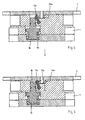
- the Fig. 4 shows a cross section through the pallet 2 and the chuck 1 in the assembled, non-tensioned state.
- the respective centering pin 20a of the pallet 2 can be inserted into the corresponding centering of the chuck 1, the piston 16 must be pneumatically moved to the initial position shown down.
- the latch 11a is located in the pivoted to the left basic position. To ensure that the latch 11a assumes the basic position when the tensioning piston 16 is in the starting position, if necessary, a spring element can be provided.
- the latch 11a is formed such that it is pressed by the respective, penetrating into the centering centering pin 20a in the starting position, ie to the left, if he should be in the operative position.
- the pneumatic pressurization of the clamping piston 16 is reduced, causing this under the action of the force of the respective spring 19 upwards in the in the Fig. 5 shifts active position shown.
- the cylindrical extension 18 presses the bolt 11a in the direction of the opposite groove flank 14a. Due to the design of the groove flank 14a and the elevation 13a of the bolt 11a of the centering pin 20a is pulled in the Z direction in the respective groove, which on the one hand takes place centering in the Z direction.
- the latch 11a is pivoted, depending on the design, by a few tenths of a millimeter to a few millimeters to the right in the operative position, in which the pallet 2 is clamped to the chuck 1 and on the Z-bearing surfaces 15a, 15b, 15c, 15d ( Fig. 2 ) rests, so that in addition to the Z positioning ultimately the direction of rotation of the pallet 2 is set to the X and Y axis.
- the centering pin 20a is dimensioned such that it does not rest on the bottom of the centering groove.
- annular piston instead of four separate clamping piston for actuating the four bars, for example, an annular piston can be provided, which is provided with four cylindrical extensions for actuating the four bars.
- the respective centering pin instead of or in addition to the recess, be provided with a survey on which a correspondingly formed clamping element engages.
Landscapes
- Mechanical Engineering (AREA)
- Engineering & Computer Science (AREA)
- Chemical & Material Sciences (AREA)
- Chemical Kinetics & Catalysis (AREA)
- Electrochemistry (AREA)
- Jigs For Machine Tools (AREA)
- Feeding Of Workpieces (AREA)
- Pallets (AREA)
- Holding Or Fastening Of Disk On Rotational Shaft (AREA)
- Container, Conveyance, Adherence, Positioning, Of Wafer (AREA)
- Gripping On Spindles (AREA)
- Mounting, Exchange, And Manufacturing Of Dies (AREA)
- Adornments (AREA)
- Making Paper Articles (AREA)
- Clamps And Clips (AREA)
- Load-Engaging Elements For Cranes (AREA)
Claims (11)
- Dispositif de serrage avec un mandrin de serrage (1) et une palette (2) pouvant y être fixée de manière amovible, le mandrin de serrage (1) étant muni d'au moins trois rainures de centrage (10a, 10b, 10c, 10d) et la palette (2) d'au moins trois tourillons de centrage (20a, 20b, 20c, 20d) correspondants, et le mandrin de serrage (1) étant doté de moyens de serrage permettant de serrer à fond la palette (2), caractérisé en ce que respectivement un flanc (14a, 14b, 14c, 14d) de la rainure de centrage (10a, 10b, 10c, 10d) est réalisé pour le centrage du tourillon de centrage (20a, 20b, 20c, 20d) respectif, alors que respectivement l'autre flanc de la rainure de centrage (10a, 10b, 10c, 10d) est formé par un élément de serrage (11a, 11b, 11c, 11d), qui est destiné à saisir au niveau d'un évidement et/ou bossage du tourillon de centrage (20a, 20b, 20c, 20d) respectif pour faire entrer le tourillon de centrage (20a, 20b, 20c, 20d) dans la direction Z dans la rainure de centrage (10a, 10b, 10c, 10d) et également le pousser contre l'autre flanc de rainure (14a, 14b, 14c, 14d).
- Dispositif de serrage selon la revendication 1, caractérisé en ce que le tourillon de centrage (20a) respectif est doté des deux côtés d'un évidement (23a, 24a) et/ou bossage et en ce que le flanc de rainure (14a) prévu pour le centrage du tourillon de centrage (20a) respectif est doté d'une forme correspondante pour faire entrer le tourillon de centrage (20a) sous l'effet dynamique de l'élément de serrage (11a) dans la direction Z dans la rainure de centrage (10a).
- Dispositif de serrage selon la revendication 1 ou 2, caractérisé en ce que le mandrin de serrage (1) est doté de quatre rainures de centrage (10a, 10b, 10c, 10d) décalées l'une par rapport à l'autre de 90° autour de l'axe Z (26) et la palette est munie de quatre tourillons de centrage (20a, 20b, 20c, 20d) correspondants, respectivement deux rainures de centrage (10a, 10c) diamétralement opposées l'une à l'autre sont réalisées pour déterminer la position de la palette (2) dans la direction X, alors que les deux autres rainures de centrage (10b, 10d) diamétralement opposées l'une à l'autre sont réalisées pour déterminer la position de la palette (2) dans la direction Y.
- Dispositif de serrage selon l'une quelconque des revendications précédentes, caractérisé en ce que l'élément de serrage respectif (11a) est réalisé sous forme de verrou pivotant, qui peut être pivoté dans la direction du flanc de rainure (14a) opposé à l'aide d'un piston de serrage (16) pouvant être déplacé dans la direction Z.
- Dispositif de serrage selon la revendication 4, caractérisé en ce que le centre de rotation de l'élément de serrage (11a) se situe sous la rainure de centrage (10a) respective.
- Dispositif de serrage selon la revendication 4 ou 5, caractérisé en ce que le piston de serrage (16) est doté d'un prolongement cylindrique (18) permettant de pivoter le verrou (11a) respectif d'une position de base à une position active.
- Dispositif de serrage selon la revendication 6, caractérisé en ce que le prolongement (18) du piston de serrage (16) est doté d'une partie avant conique.
- Dispositif de serrage selon l'une quelconque des revendications 4 à 7, caractérisé en ce que le piston de serrage (16) est chargé à l'aide d'un ressort (19) dans la direction de l'élément de serrage (11a).
- Dispositif de serrage selon l'une quelconque des revendications précédentes, caractérisé en ce que le mandrin de serrage (1) est muni d'une ouverture (6) centrale continue.
- Dispositif de serrage selon l'une quelconque des revendications précédentes, caractérisé en ce que le mandrin de serrage (1) présente entre deux rainures de centrage (10a, 10b ; 10b, 10c ; 10c, 10d ; 10d, 10a) adjacentes respectivement une surface d'appui (15a, 15b, 15c, 15d) servant de référence Z.
- Dispositif de serrage selon la revendication 10, caractérisé en ce que les surfaces d'appui (15a, 15b, 15c, 15d) servant de référence Z sont réalisées essentiellement en forme de segment d'un anneau de cercle.
Priority Applications (2)
| Application Number | Priority Date | Filing Date | Title |
|---|---|---|---|
| SI200530243T SI1595641T1 (sl) | 2004-04-22 | 2005-03-08 | Vpenjalna naprava z vpenjalno glavo in paleto, ki jo je mogoče nanjo ločljivo pritrditi |
| PL05405228T PL1595641T3 (pl) | 2004-04-22 | 2005-03-08 | Urządzenie mocujące z uchwytem zaciskowym i ustalaną na nim rozłącznie paletą |
Applications Claiming Priority (2)
| Application Number | Priority Date | Filing Date | Title |
|---|---|---|---|
| CH7012004 | 2004-04-22 | ||
| CH7012004 | 2004-04-22 |
Publications (2)
| Publication Number | Publication Date |
|---|---|
| EP1595641A1 EP1595641A1 (fr) | 2005-11-16 |
| EP1595641B1 true EP1595641B1 (fr) | 2008-02-27 |
Family
ID=34942933
Family Applications (1)
| Application Number | Title | Priority Date | Filing Date |
|---|---|---|---|
| EP05405228A Expired - Lifetime EP1595641B1 (fr) | 2004-04-22 | 2005-03-08 | Dispositif de serrage avec mandrin et palette fixé de façon amovible sur le mandrin. |
Country Status (22)
| Country | Link |
|---|---|
| US (1) | US7303195B2 (fr) |
| EP (1) | EP1595641B1 (fr) |
| JP (1) | JP4263702B2 (fr) |
| KR (1) | KR101053777B1 (fr) |
| CN (1) | CN1689752B (fr) |
| AT (1) | ATE387287T1 (fr) |
| AU (1) | AU2005201101B2 (fr) |
| BR (1) | BRPI0501413A (fr) |
| CA (1) | CA2501113C (fr) |
| DE (1) | DE502005002952D1 (fr) |
| DK (1) | DK1595641T3 (fr) |
| ES (1) | ES2300966T3 (fr) |
| IL (1) | IL167450A (fr) |
| MX (1) | MXPA05004327A (fr) |
| MY (1) | MY139402A (fr) |
| NO (1) | NO20051982L (fr) |
| PL (1) | PL1595641T3 (fr) |
| RU (1) | RU2308366C2 (fr) |
| SG (1) | SG116664A1 (fr) |
| SI (1) | SI1595641T1 (fr) |
| TW (1) | TWI337912B (fr) |
| UA (1) | UA83643C2 (fr) |
Families Citing this family (32)
| Publication number | Priority date | Publication date | Assignee | Title |
|---|---|---|---|---|
| IL180448A0 (en) * | 2006-01-30 | 2007-06-03 | Tool Internat Ag F | Clamping apparatus |
| MY144060A (en) * | 2006-12-14 | 2011-08-15 | Erowa Ag | Work piece carrier for exactly positioning a work piece on a chuck and clamping apparatus with a chuck and a work piece carrier |
| CH716410B1 (de) * | 2007-01-30 | 2021-01-29 | Erowa Ag | Spanneinrichtung mit einem Spannfutter und einem lösbar daran fixierbaren Werkstückträger. |
| WO2008136049A1 (fr) * | 2007-04-20 | 2008-11-13 | Pascal Engineering Corporation | Dispositif de positionnement et de fixation pour palette de travail |
| EP2036661A1 (fr) * | 2007-09-17 | 2009-03-18 | System 3R International AB | Procédé et dispositif de positionnement d'un outil ou d'une pièce à usiner |
| TWI409133B (zh) * | 2008-06-27 | 2013-09-21 | Hon Hai Prec Ind Co Ltd | 夾持裝置 |
| WO2011143789A1 (fr) * | 2010-05-18 | 2011-11-24 | Apple Inc. | Accessoire amovible pour dispositif de fabrication |
| DE202010010413U1 (de) * | 2010-07-19 | 2011-10-25 | Gressel Ag | Nullpunkt-Spannvorrichtung |
| CN103659351B (zh) * | 2012-09-07 | 2016-12-28 | 安溪县景宏技术咨询有限公司 | 锁紧机构 |
| HK1181961A2 (en) * | 2012-09-27 | 2013-11-15 | Gainteam Holdings Limited | Holder for a sheet of metal |
| CN103170856B (zh) * | 2013-04-18 | 2015-04-15 | 常州比优特机械设备制造有限公司 | 钢圈加工用气动夹具 |
| CH708745A1 (de) * | 2013-10-25 | 2015-04-30 | Erowa Ag | Spanneinrichtung. |
| CN104015065B (zh) * | 2014-05-16 | 2016-04-20 | 安徽合力股份有限公司 | 用于叉车差速器壳体的车削定位工装 |
| ES2684402T3 (es) * | 2014-06-19 | 2018-10-02 | System 3R International Ab | Plataforma para mandriles de sujeción |
| CN104526409A (zh) * | 2014-12-26 | 2015-04-22 | 哈尔滨汽轮机厂有限责任公司 | 管板加工的装卡装置 |
| JP6733877B2 (ja) * | 2015-02-23 | 2020-08-05 | ボアトー,クリストフ | 迅速組み立てシステム |
| US9604330B2 (en) * | 2015-03-12 | 2017-03-28 | Jia Sin Precision Co., Ltd. | Positioning block structure for machining fixture |
| JP6628076B2 (ja) * | 2015-06-30 | 2020-01-08 | Smc株式会社 | チャック装置 |
| JP6759535B2 (ja) * | 2015-07-10 | 2020-09-23 | セイコーエプソン株式会社 | ワーク供給装置、ピッキング装置、時計組立て装置、およびピッキング方法 |
| RU182192U1 (ru) * | 2016-04-14 | 2018-08-07 | Александр Николаевич Куприй | Устройство жесткого крепления массивного цилиндроподобного полого крупногабаритного изделия к шпинделю станка |
| CH712703A1 (de) | 2016-06-30 | 2018-01-15 | Erowa Ag | Spanneinrichtung sowie Spannsystem. |
| DE102016219728A1 (de) * | 2016-10-11 | 2018-04-12 | Mag Ias Gmbh | Haltevorrichtung zum Positionieren und Fixieren einer Werkstückadaptervorrichtung und Werkstückadaptervorrichtung zum Positionieren und Fixieren eines Werkstücks mittels einer derartigen Haltevorrichtung sowie Haltevorrichtung-Werkstückadaptervorrichtung-Anordnung |
| ES2826397T3 (es) * | 2018-06-29 | 2021-05-18 | System 3R Int Ab | Sistema de sujeción modular |
| CN108817435B (zh) * | 2018-08-23 | 2020-08-18 | 浙江中星制针股份有限公司 | 一种用于车铣复合机床的制动蹄治具 |
| CN111156883B (zh) * | 2020-01-02 | 2022-04-12 | 北京半导体专用设备研究所(中国电子科技集团公司第四十五研究所) | 固定装置及使用该固定装置的空心柱状器件测试设备 |
| DE102020105722A1 (de) * | 2020-03-03 | 2021-09-09 | Hvm Technology Gmbh | Nullpunktspannplatte, und Werkzeugmaschine mit selbiger |
| CN112589171A (zh) * | 2020-12-02 | 2021-04-02 | 四川航天长征装备制造有限公司 | 一种带有周向凸台的回转类零件的铣削夹持工装与加工方法 |
| CN113510256B (zh) * | 2021-08-03 | 2022-05-27 | 亿缙机械(嘉兴)有限公司 | 一种基于球窝加工用带有防变形扶持结构的工装夹具 |
| CN113909940B (zh) * | 2021-09-08 | 2023-11-10 | 沪东重机有限公司 | 一种用于中速机机架的定位装夹夹具 |
| CN113751742B (zh) * | 2021-10-08 | 2022-11-04 | 湖南金源柯重工科技有限公司 | 一种双卡盘固定的数控加工设备 |
| DE102022105715B3 (de) | 2022-03-10 | 2023-07-13 | Gröbner Fertigungs GmbH | Befestigungsanordnung für eine Bearbeitungsmachine und Verfahren zum Betätigen der Befestigungsanordnung |
| IT202300009756A1 (it) * | 2023-05-15 | 2024-11-15 | Kosme Srl Unipersonale | Piattello per una macchina a giostra e macchina a giostra che lo comprende |
Family Cites Families (15)
| Publication number | Priority date | Publication date | Assignee | Title |
|---|---|---|---|---|
| DD205108B1 (de) * | 1981-12-03 | 1986-05-07 | Bernhard Drassdo | Mehrdimensionale, spielfreie genauigkeitsfixiereinheit fuer bewegliche bauelemente |
| US4647051A (en) * | 1985-05-03 | 1987-03-03 | Sheffer Collet Company | Support for a chuck |
| US4855558A (en) * | 1986-07-29 | 1989-08-08 | System 3R International Ab | Clamping device for a tool at a machine tool, particularly at a die sinking electric discharge machine |
| DE3919077C1 (fr) * | 1989-06-10 | 1990-07-26 | Erowa Ag, Reinach, Ch | |
| RU2104127C1 (ru) * | 1992-07-28 | 1998-02-10 | Алексей Иванович Рудич | Пневматический гидропластовый патрон |
| DE4307342C2 (de) * | 1993-03-09 | 1994-12-08 | Erowa Ag | Einrichtung zum positionsdefinierten Aufspannen eines Werkstücks am Arbeitsplatz einer Bearbeitungsmaschine |
| ATE280011T1 (de) * | 1999-07-14 | 2004-11-15 | Erowa Ag | Einrichtung zum positionsdefinierten aufspannen eines werkstücks im arbeitsbereich einer bearbeitungsmaschine |
| US6354606B1 (en) * | 2000-05-19 | 2002-03-12 | Xtek, Inc. | Chuck adapter assembly and related method for converting a fixed chuck to a compensating chuck |
| DE10031103A1 (de) * | 2000-06-30 | 2002-01-10 | Grob Werke Dr H C Mult Dipl In | Positionierungs- und Spannsystem |
| JP2002361533A (ja) * | 2001-06-07 | 2002-12-18 | Kosmek Ltd | データム機能付きクランプ装置 |
| DE10155077B4 (de) * | 2001-11-09 | 2004-07-29 | Lang, Günter | Wiederholgenaue Spanneinrichtung |
| ATE267664T1 (de) * | 2002-03-11 | 2004-06-15 | Erowa Ag | Spanneinrichtung mit einem spannfutter und einem darin festspannbaren spannzapfen |
| CN2539585Y (zh) * | 2002-04-19 | 2003-03-12 | 勤扬工业股份有限公司 | 夹头 |
| DK1602426T3 (da) * | 2004-05-04 | 2014-01-13 | Erowa Ag | Spændeindretning til positionsnøjagtig fastgørelse af en spændetang i en spændepatron |
| DK1666195T3 (da) * | 2004-12-01 | 2007-09-03 | Erowa Ag | Spændeindretning til lösbar fiksering af en palle med et dæmpningselement |
-
2005
- 2005-03-08 SI SI200530243T patent/SI1595641T1/sl unknown
- 2005-03-08 DE DE502005002952T patent/DE502005002952D1/de not_active Expired - Lifetime
- 2005-03-08 EP EP05405228A patent/EP1595641B1/fr not_active Expired - Lifetime
- 2005-03-08 PL PL05405228T patent/PL1595641T3/pl unknown
- 2005-03-08 ES ES05405228T patent/ES2300966T3/es not_active Expired - Lifetime
- 2005-03-08 DK DK05405228T patent/DK1595641T3/da active
- 2005-03-08 AT AT05405228T patent/ATE387287T1/de active
- 2005-03-14 AU AU2005201101A patent/AU2005201101B2/en not_active Ceased
- 2005-03-15 IL IL167450A patent/IL167450A/en not_active IP Right Cessation
- 2005-03-17 CA CA002501113A patent/CA2501113C/fr not_active Expired - Fee Related
- 2005-03-17 SG SG200502746A patent/SG116664A1/en unknown
- 2005-03-25 JP JP2005089158A patent/JP4263702B2/ja not_active Expired - Fee Related
- 2005-04-06 MY MYPI20051550A patent/MY139402A/en unknown
- 2005-04-14 US US11/106,276 patent/US7303195B2/en active Active
- 2005-04-19 BR BRPI0501413-1A patent/BRPI0501413A/pt not_active IP Right Cessation
- 2005-04-20 UA UAA200503769A patent/UA83643C2/ru unknown
- 2005-04-21 RU RU2005112056/02A patent/RU2308366C2/ru not_active IP Right Cessation
- 2005-04-21 KR KR1020050032954A patent/KR101053777B1/ko not_active Expired - Fee Related
- 2005-04-21 TW TW094112682A patent/TWI337912B/zh not_active IP Right Cessation
- 2005-04-22 CN CN2005100674541A patent/CN1689752B/zh not_active Expired - Fee Related
- 2005-04-22 NO NO20051982A patent/NO20051982L/no not_active Application Discontinuation
- 2005-04-22 MX MXPA05004327A patent/MXPA05004327A/es active IP Right Grant
Also Published As
| Publication number | Publication date |
|---|---|
| EP1595641A1 (fr) | 2005-11-16 |
| UA83643C2 (ru) | 2008-08-11 |
| MY139402A (en) | 2009-09-30 |
| US7303195B2 (en) | 2007-12-04 |
| SG116664A1 (en) | 2005-11-28 |
| NO20051982L (no) | 2005-10-24 |
| ATE387287T1 (de) | 2008-03-15 |
| DE502005002952D1 (de) | 2008-04-10 |
| TW200602151A (en) | 2006-01-16 |
| HK1082932A1 (en) | 2006-06-23 |
| AU2005201101A1 (en) | 2005-11-10 |
| BRPI0501413A (pt) | 2006-12-12 |
| RU2308366C2 (ru) | 2007-10-20 |
| CA2501113C (fr) | 2007-05-22 |
| ES2300966T3 (es) | 2008-06-16 |
| PL1595641T3 (pl) | 2008-05-30 |
| SI1595641T1 (sl) | 2008-08-31 |
| JP2005305638A (ja) | 2005-11-04 |
| JP4263702B2 (ja) | 2009-05-13 |
| IL167450A (en) | 2009-11-18 |
| CN1689752B (zh) | 2012-02-22 |
| US20050238450A1 (en) | 2005-10-27 |
| KR20060047300A (ko) | 2006-05-18 |
| AU2005201101B2 (en) | 2010-08-12 |
| NO20051982D0 (no) | 2005-04-22 |
| TWI337912B (en) | 2011-03-01 |
| RU2005112056A (ru) | 2006-10-27 |
| CA2501113A1 (fr) | 2005-10-22 |
| DK1595641T3 (da) | 2008-06-23 |
| KR101053777B1 (ko) | 2011-08-02 |
| MXPA05004327A (es) | 2012-03-29 |
| CN1689752A (zh) | 2005-11-02 |
Similar Documents
| Publication | Publication Date | Title |
|---|---|---|
| EP1595641B1 (fr) | Dispositif de serrage avec mandrin et palette fixé de façon amovible sur le mandrin. | |
| EP2085177B1 (fr) | Dispositif de serrage pour le serrage fixe de pièces usinées | |
| DE60001028T2 (de) | Spannvorrichtung mit Ausrichtfunktion | |
| DE69701597T2 (de) | Schwenkspanner | |
| EP1321221A1 (fr) | Dispositif de fixation avec mandrin de serrage et porte-pièce pouvant être fixé de façon amovible à celui-ci | |
| EP2025471A2 (fr) | Crampon plaqueur | |
| WO2012010463A1 (fr) | Dispositif de serrage à point zéro | |
| EP0753368B1 (fr) | Dispositif de serrage pour la fixation relative précise de 2 pièces | |
| EP3638453B1 (fr) | Procédé, dispositif et élément auxiliaire pour la retenue d'une pièce | |
| EP2747922B1 (fr) | Procédé et dispositif pour fixer une pièce sur une partie de machine rotative | |
| EP0450383B1 (fr) | Dispositif de serrage et de centrage | |
| EP3851249B1 (fr) | Dispositif de serrage de pièce | |
| EP1738864A2 (fr) | Dispositif de serrage | |
| DE19842090A1 (de) | Fluiddruckspannfutter | |
| EP1600261B1 (fr) | Dispositif de serrage pour le serrage de composants | |
| EP3964332A1 (fr) | Dispositif de serrage | |
| EP3043954B1 (fr) | Dispositif de serrage d'au moins un téton de serrage | |
| DE102018119980A1 (de) | Spann- oder Greifeinrichtung | |
| EP3620260B1 (fr) | Dispositif compensateur permettant de compenser une tolérance de positionnement | |
| DE102015104058B3 (de) | Zentrische Spannvorrichtung | |
| WO2009074273A2 (fr) | Dispositif pour serrer un porte-outil sur un mandrin de serrage pouvant être fixé sur une machine d'usinage | |
| DE19826328C1 (de) | Schnell-Paß-System für Bauteile von Werkzeugmaschinen | |
| EP2910325A1 (fr) | Tourelle revolver | |
| EP1579948B1 (fr) | Dispositif de serrage | |
| DE9405030U1 (de) | Palettenspannsystem |
Legal Events
| Date | Code | Title | Description |
|---|---|---|---|
| PUAI | Public reference made under article 153(3) epc to a published international application that has entered the european phase |
Free format text: ORIGINAL CODE: 0009012 |
|
| AK | Designated contracting states |
Kind code of ref document: A1 Designated state(s): AT BE BG CH CY CZ DE DK EE ES FI FR GB GR HU IE IS IT LI LT LU MC NL PL PT RO SE SI SK TR |
|
| AX | Request for extension of the european patent |
Extension state: AL BA HR LV MK YU |
|
| 17P | Request for examination filed |
Effective date: 20051128 |
|
| AKX | Designation fees paid |
Designated state(s): AT BE BG CH CY CZ DE DK EE ES FI FR GB GR HU IE IS IT LI LT LU MC NL PL PT RO SE SI SK TR |
|
| AXX | Extension fees paid |
Extension state: YU Payment date: 20050316 Extension state: LV Payment date: 20050316 Extension state: HR Payment date: 20050316 |
|
| GRAP | Despatch of communication of intention to grant a patent |
Free format text: ORIGINAL CODE: EPIDOSNIGR1 |
|
| GRAS | Grant fee paid |
Free format text: ORIGINAL CODE: EPIDOSNIGR3 |
|
| GRAA | (expected) grant |
Free format text: ORIGINAL CODE: 0009210 |
|
| AK | Designated contracting states |
Kind code of ref document: B1 Designated state(s): AT BE BG CH CY CZ DE DK EE ES FI FR GB GR HU IE IS IT LI LT LU MC NL PL PT RO SE SI SK TR |
|
| AX | Request for extension of the european patent |
Extension state: HR LV YU |
|
| REG | Reference to a national code |
Ref country code: GB Ref legal event code: FG4D Free format text: NOT ENGLISH |
|
| REG | Reference to a national code |
Ref country code: CH Ref legal event code: EP Ref country code: CH Ref legal event code: NV Representative=s name: ROTTMANN, ZIMMERMANN + PARTNER AG |
|
| REG | Reference to a national code |
Ref country code: IE Ref legal event code: FG4D Free format text: LANGUAGE OF EP DOCUMENT: GERMAN |
|
| REF | Corresponds to: |
Ref document number: 502005002952 Country of ref document: DE Date of ref document: 20080410 Kind code of ref document: P |
|
| REG | Reference to a national code |
Ref country code: PL Ref legal event code: T3 |
|
| REG | Reference to a national code |
Ref country code: SE Ref legal event code: TRGR |
|
| REG | Reference to a national code |
Ref country code: ES Ref legal event code: FG2A Ref document number: 2300966 Country of ref document: ES Kind code of ref document: T3 |
|
| REG | Reference to a national code |
Ref country code: DK Ref legal event code: T3 |
|
| REG | Reference to a national code |
Ref country code: HU Ref legal event code: AG4A Ref document number: E003036 Country of ref document: HU |
|
| PG25 | Lapsed in a contracting state [announced via postgrant information from national office to epo] |
Ref country code: FI Free format text: LAPSE BECAUSE OF FAILURE TO SUBMIT A TRANSLATION OF THE DESCRIPTION OR TO PAY THE FEE WITHIN THE PRESCRIBED TIME-LIMIT Effective date: 20080227 Ref country code: IS Free format text: LAPSE BECAUSE OF FAILURE TO SUBMIT A TRANSLATION OF THE DESCRIPTION OR TO PAY THE FEE WITHIN THE PRESCRIBED TIME-LIMIT Effective date: 20080627 |
|
| PGFP | Annual fee paid to national office [announced via postgrant information from national office to epo] |
Ref country code: HU Payment date: 20080402 Year of fee payment: 4 |
|
| ET | Fr: translation filed | ||
| PGFP | Annual fee paid to national office [announced via postgrant information from national office to epo] |
Ref country code: SI Payment date: 20080321 Year of fee payment: 4 Ref country code: BE Payment date: 20080416 Year of fee payment: 4 |
|
| REG | Reference to a national code |
Ref country code: IE Ref legal event code: FD4D |
|
| PG25 | Lapsed in a contracting state [announced via postgrant information from national office to epo] |
Ref country code: IE Free format text: LAPSE BECAUSE OF FAILURE TO SUBMIT A TRANSLATION OF THE DESCRIPTION OR TO PAY THE FEE WITHIN THE PRESCRIBED TIME-LIMIT Effective date: 20080227 Ref country code: PT Free format text: LAPSE BECAUSE OF FAILURE TO SUBMIT A TRANSLATION OF THE DESCRIPTION OR TO PAY THE FEE WITHIN THE PRESCRIBED TIME-LIMIT Effective date: 20080721 Ref country code: MC Free format text: LAPSE BECAUSE OF NON-PAYMENT OF DUE FEES Effective date: 20080331 |
|
| PG25 | Lapsed in a contracting state [announced via postgrant information from national office to epo] |
Ref country code: RO Free format text: LAPSE BECAUSE OF FAILURE TO SUBMIT A TRANSLATION OF THE DESCRIPTION OR TO PAY THE FEE WITHIN THE PRESCRIBED TIME-LIMIT Effective date: 20080227 |
|
| PLBE | No opposition filed within time limit |
Free format text: ORIGINAL CODE: 0009261 |
|
| STAA | Information on the status of an ep patent application or granted ep patent |
Free format text: STATUS: NO OPPOSITION FILED WITHIN TIME LIMIT |
|
| PG25 | Lapsed in a contracting state [announced via postgrant information from national office to epo] |
Ref country code: EE Free format text: LAPSE BECAUSE OF FAILURE TO SUBMIT A TRANSLATION OF THE DESCRIPTION OR TO PAY THE FEE WITHIN THE PRESCRIBED TIME-LIMIT Effective date: 20080227 Ref country code: LT Free format text: LAPSE BECAUSE OF FAILURE TO SUBMIT A TRANSLATION OF THE DESCRIPTION OR TO PAY THE FEE WITHIN THE PRESCRIBED TIME-LIMIT Effective date: 20080227 |
|
| 26N | No opposition filed |
Effective date: 20081128 |
|
| PG25 | Lapsed in a contracting state [announced via postgrant information from national office to epo] |
Ref country code: BG Free format text: LAPSE BECAUSE OF FAILURE TO SUBMIT A TRANSLATION OF THE DESCRIPTION OR TO PAY THE FEE WITHIN THE PRESCRIBED TIME-LIMIT Effective date: 20080527 |
|
| PGFP | Annual fee paid to national office [announced via postgrant information from national office to epo] |
Ref country code: ES Payment date: 20090327 Year of fee payment: 5 |
|
| PG25 | Lapsed in a contracting state [announced via postgrant information from national office to epo] |
Ref country code: CY Free format text: LAPSE BECAUSE OF FAILURE TO SUBMIT A TRANSLATION OF THE DESCRIPTION OR TO PAY THE FEE WITHIN THE PRESCRIBED TIME-LIMIT Effective date: 20080227 |
|
| BERE | Be: lapsed |
Owner name: EROWA A.G. Effective date: 20090331 |
|
| REG | Reference to a national code |
Ref country code: SI Ref legal event code: KO00 Effective date: 20091029 |
|
| PG25 | Lapsed in a contracting state [announced via postgrant information from national office to epo] |
Ref country code: HU Free format text: LAPSE BECAUSE OF NON-PAYMENT OF DUE FEES Effective date: 20090309 |
|
| PG25 | Lapsed in a contracting state [announced via postgrant information from national office to epo] |
Ref country code: SI Free format text: LAPSE BECAUSE OF NON-PAYMENT OF DUE FEES Effective date: 20090309 Ref country code: BE Free format text: LAPSE BECAUSE OF NON-PAYMENT OF DUE FEES Effective date: 20090331 |
|
| PGFP | Annual fee paid to national office [announced via postgrant information from national office to epo] |
Ref country code: DK Payment date: 20100310 Year of fee payment: 6 |
|
| PG25 | Lapsed in a contracting state [announced via postgrant information from national office to epo] |
Ref country code: LU Free format text: LAPSE BECAUSE OF NON-PAYMENT OF DUE FEES Effective date: 20080308 |
|
| PG25 | Lapsed in a contracting state [announced via postgrant information from national office to epo] |
Ref country code: TR Free format text: LAPSE BECAUSE OF FAILURE TO SUBMIT A TRANSLATION OF THE DESCRIPTION OR TO PAY THE FEE WITHIN THE PRESCRIBED TIME-LIMIT Effective date: 20080227 |
|
| PGFP | Annual fee paid to national office [announced via postgrant information from national office to epo] |
Ref country code: NL Payment date: 20100315 Year of fee payment: 6 |
|
| PG25 | Lapsed in a contracting state [announced via postgrant information from national office to epo] |
Ref country code: GR Free format text: LAPSE BECAUSE OF FAILURE TO SUBMIT A TRANSLATION OF THE DESCRIPTION OR TO PAY THE FEE WITHIN THE PRESCRIBED TIME-LIMIT Effective date: 20080528 |
|
| REG | Reference to a national code |
Ref country code: CH Ref legal event code: PFA Owner name: EROWA AG Free format text: EROWA AG#WINKELSTRASSE 8#CH-5734 REINACH (CH) -TRANSFER TO- EROWA AG#WINKELSTRASSE 8#CH-5734 REINACH (CH) |
|
| REG | Reference to a national code |
Ref country code: NL Ref legal event code: V1 Effective date: 20111001 |
|
| REG | Reference to a national code |
Ref country code: DK Ref legal event code: EBP |
|
| REG | Reference to a national code |
Ref country code: ES Ref legal event code: FD2A Effective date: 20111118 |
|
| PG25 | Lapsed in a contracting state [announced via postgrant information from national office to epo] |
Ref country code: ES Free format text: LAPSE BECAUSE OF NON-PAYMENT OF DUE FEES Effective date: 20100309 Ref country code: NL Free format text: LAPSE BECAUSE OF NON-PAYMENT OF DUE FEES Effective date: 20111001 |
|
| PG25 | Lapsed in a contracting state [announced via postgrant information from national office to epo] |
Ref country code: DK Free format text: LAPSE BECAUSE OF NON-PAYMENT OF DUE FEES Effective date: 20110331 |
|
| PGFP | Annual fee paid to national office [announced via postgrant information from national office to epo] |
Ref country code: GB Payment date: 20120322 Year of fee payment: 8 |
|
| GBPC | Gb: european patent ceased through non-payment of renewal fee |
Effective date: 20130308 |
|
| PG25 | Lapsed in a contracting state [announced via postgrant information from national office to epo] |
Ref country code: GB Free format text: LAPSE BECAUSE OF NON-PAYMENT OF DUE FEES Effective date: 20130308 |
|
| PGFP | Annual fee paid to national office [announced via postgrant information from national office to epo] |
Ref country code: IT Payment date: 20140326 Year of fee payment: 10 Ref country code: PL Payment date: 20140219 Year of fee payment: 10 |
|
| PG25 | Lapsed in a contracting state [announced via postgrant information from national office to epo] |
Ref country code: IT Free format text: LAPSE BECAUSE OF NON-PAYMENT OF DUE FEES Effective date: 20150308 |
|
| REG | Reference to a national code |
Ref country code: FR Ref legal event code: PLFP Year of fee payment: 12 |
|
| PG25 | Lapsed in a contracting state [announced via postgrant information from national office to epo] |
Ref country code: PL Free format text: LAPSE BECAUSE OF NON-PAYMENT OF DUE FEES Effective date: 20150308 |
|
| REG | Reference to a national code |
Ref country code: CH Ref legal event code: PCAR Free format text: NEW ADDRESS: GARTENSTRASSE 28 A, 5400 BADEN (CH) |
|
| REG | Reference to a national code |
Ref country code: FR Ref legal event code: PLFP Year of fee payment: 13 |
|
| PGFP | Annual fee paid to national office [announced via postgrant information from national office to epo] |
Ref country code: FR Payment date: 20170322 Year of fee payment: 13 |
|
| PGFP | Annual fee paid to national office [announced via postgrant information from national office to epo] |
Ref country code: AT Payment date: 20170322 Year of fee payment: 13 |
|
| PGFP | Annual fee paid to national office [announced via postgrant information from national office to epo] |
Ref country code: SE Payment date: 20180321 Year of fee payment: 14 |
|
| REG | Reference to a national code |
Ref country code: AT Ref legal event code: MM01 Ref document number: 387287 Country of ref document: AT Kind code of ref document: T Effective date: 20180308 |
|
| PG25 | Lapsed in a contracting state [announced via postgrant information from national office to epo] |
Ref country code: AT Free format text: LAPSE BECAUSE OF NON-PAYMENT OF DUE FEES Effective date: 20180308 |
|
| PG25 | Lapsed in a contracting state [announced via postgrant information from national office to epo] |
Ref country code: FR Free format text: LAPSE BECAUSE OF NON-PAYMENT OF DUE FEES Effective date: 20180331 |
|
| REG | Reference to a national code |
Ref country code: SE Ref legal event code: EUG |
|
| PG25 | Lapsed in a contracting state [announced via postgrant information from national office to epo] |
Ref country code: SE Free format text: LAPSE BECAUSE OF NON-PAYMENT OF DUE FEES Effective date: 20190309 |
|
| PGFP | Annual fee paid to national office [announced via postgrant information from national office to epo] |
Ref country code: CZ Payment date: 20210226 Year of fee payment: 17 |
|
| PGFP | Annual fee paid to national office [announced via postgrant information from national office to epo] |
Ref country code: SK Payment date: 20210304 Year of fee payment: 17 |
|
| PGFP | Annual fee paid to national office [announced via postgrant information from national office to epo] |
Ref country code: DE Payment date: 20220322 Year of fee payment: 18 Ref country code: CH Payment date: 20220321 Year of fee payment: 18 |
|
| REG | Reference to a national code |
Ref country code: SK Ref legal event code: MM4A Ref document number: E 3520 Country of ref document: SK Effective date: 20220308 |
|
| PG25 | Lapsed in a contracting state [announced via postgrant information from national office to epo] |
Ref country code: CZ Free format text: LAPSE BECAUSE OF NON-PAYMENT OF DUE FEES Effective date: 20220308 |
|
| PG25 | Lapsed in a contracting state [announced via postgrant information from national office to epo] |
Ref country code: SK Free format text: LAPSE BECAUSE OF NON-PAYMENT OF DUE FEES Effective date: 20220308 |
|
| REG | Reference to a national code |
Ref country code: DE Ref legal event code: R119 Ref document number: 502005002952 Country of ref document: DE |
|
| REG | Reference to a national code |
Ref country code: CH Ref legal event code: PL |
|
| PG25 | Lapsed in a contracting state [announced via postgrant information from national office to epo] |
Ref country code: LI Free format text: LAPSE BECAUSE OF NON-PAYMENT OF DUE FEES Effective date: 20230331 Ref country code: DE Free format text: LAPSE BECAUSE OF NON-PAYMENT OF DUE FEES Effective date: 20231003 Ref country code: CH Free format text: LAPSE BECAUSE OF NON-PAYMENT OF DUE FEES Effective date: 20230331 |