EP1595495A2 - Dispositif dentaire pour l'examen de charactéristiques optiques dentaires - Google Patents
Dispositif dentaire pour l'examen de charactéristiques optiques dentaires Download PDFInfo
- Publication number
- EP1595495A2 EP1595495A2 EP05010492A EP05010492A EP1595495A2 EP 1595495 A2 EP1595495 A2 EP 1595495A2 EP 05010492 A EP05010492 A EP 05010492A EP 05010492 A EP05010492 A EP 05010492A EP 1595495 A2 EP1595495 A2 EP 1595495A2
- Authority
- EP
- European Patent Office
- Prior art keywords
- handpiece
- radiation
- response
- dental
- sleeve
- Prior art date
- Legal status (The legal status is an assumption and is not a legal conclusion. Google has not performed a legal analysis and makes no representation as to the accuracy of the status listed.)
- Granted
Links
Images





Classifications
-
- A—HUMAN NECESSITIES
- A61—MEDICAL OR VETERINARY SCIENCE; HYGIENE
- A61B—DIAGNOSIS; SURGERY; IDENTIFICATION
- A61B5/00—Measuring for diagnostic purposes; Identification of persons
- A61B5/0059—Measuring for diagnostic purposes; Identification of persons using light, e.g. diagnosis by transillumination, diascopy, fluorescence
- A61B5/0082—Measuring for diagnostic purposes; Identification of persons using light, e.g. diagnosis by transillumination, diascopy, fluorescence adapted for particular medical purposes
- A61B5/0088—Measuring for diagnostic purposes; Identification of persons using light, e.g. diagnosis by transillumination, diascopy, fluorescence adapted for particular medical purposes for oral or dental tissue
-
- A—HUMAN NECESSITIES
- A61—MEDICAL OR VETERINARY SCIENCE; HYGIENE
- A61B—DIAGNOSIS; SURGERY; IDENTIFICATION
- A61B5/00—Measuring for diagnostic purposes; Identification of persons
- A61B5/74—Details of notification to user or communication with user or patient; User input means
- A61B5/742—Details of notification to user or communication with user or patient; User input means using visual displays
-
- A—HUMAN NECESSITIES
- A61—MEDICAL OR VETERINARY SCIENCE; HYGIENE
- A61B—DIAGNOSIS; SURGERY; IDENTIFICATION
- A61B2562/00—Details of sensors; Constructional details of sensor housings or probes; Accessories for sensors
- A61B2562/24—Hygienic packaging for medical sensors; Maintaining apparatus for sensor hygiene
- A61B2562/247—Hygienic covers, i.e. for covering the sensor or apparatus during use
-
- A—HUMAN NECESSITIES
- A61—MEDICAL OR VETERINARY SCIENCE; HYGIENE
- A61B—DIAGNOSIS; SURGERY; IDENTIFICATION
- A61B5/00—Measuring for diagnostic purposes; Identification of persons
- A61B5/0002—Remote monitoring of patients using telemetry, e.g. transmission of vital signals via a communication network
Definitions
- the present invention relates to a dental device for examination the optical properties of tooth tissue according to the preamble of Claim 1.
- the present invention relates to a device for Detection of fluorescent substances on teeth, for example caries, Plaque, bacterial infestation, concrements or tartar.
- the dental diagnostics are optical examination devices, with whose help For example, caries, plaque, bacterial infestation, concrements or tartar detected can be, has been known for some time and in different variants.
- all known devices have in common that a to be examined Tooth tissue area is first irradiated with an excitation radiation, whereupon from the tooth a response radiation is delivered.
- This response radiation can both the reflected back radiation of the same wavelength and a Include fluorescence radiation.
- the response radiation is detected again and supplied to an evaluation unit, which on the basis of the spectrum of the response radiation determines if any of the above substances are present or not.
- the known optical diagnostic methods and devices differ by the wavelength (s) used for the excitation radiation and by the Evaluation of the detected response radiation.
- a first option is to investigate whether fluorescence radiation is acting on the tooth in response to the Excitation radiation has arisen out.
- Another possibility is with the So-called reflection spectrometry is to investigate which wavelengths of the tooth surface are reflected in what way.
- Devices of this type are described for example in DE 297 04 185 U1, the DE 197 09 500 C1 or DE 100 13 210 A1.
- These known Devices have a dental handpiece with an examination probe, via which the excitation radiation is directed to the tooth to be examined as well the reflected radiation from the tooth is detected.
- the light source for Generation of the excitation radiation is often directly in the handpiece while the evaluation of the response radiation predominantly in a console, which via a connecting hose with the handpiece connected is.
- This console has on the one hand the electronics for controlling the Light source for the excitation radiation as well as for the evaluation of Response radiation on.
- console display means in the form of a Displays are provided which represent the measurement result and thus information about it indicate whether the area just examined is one of the above fluorescent Has substances or not.
- final diagnosis i. the Determining whether the increased fluorescence is caused by caries or not then the dentist creates.
- the present invention is based on the task, the handling to date known dental optical examination facilities improve. It should be noted that for a user of the device It should also be possible to access areas that are difficult to access within the To examine the oral cavity of a patient. Furthermore, the possibility of a simple cleaning, since in particular those parts which in the Mouth of the patient reach, also need to be sterilized.
- the To design a dental examination device such that they by a Hand device is formed, which in principle completely independent of others Facilities can be used and all the essentials and to carry out the Having required optical diagnostic method elements.
- the Device according to the invention thus consists of means for generating a Excitation radiation, which on a tooth tissue area to be examined is steering, detection means and evaluation means for detecting and evaluating a from the irradiated tooth tissue area in response to the irradiation reflected radiation and display means for displaying a the evaluation means based on the detected response radiation determined Measurement result, wherein the means for generating the excitation radiation, the Detection means and at least also the display means in or on a handpiece are arranged.
- the display means for displaying the measurement result can thereby be both optical and acoustic nature and the user of the device immediately communicate the current measurement result.
- the Evaluation means integrated in the handpiece.
- the optical examination device Due to the design of the optical examination device as autonomous working handpiece, the user of the device is no longer in his Restricted mobility. The handling of the device is thus in Compared to the known devices in which the handpiece over a Supply hose connected to a console, significantly improved.
- the measurement results produced by the examination device to supplement or further process wirelessly to an external presentation and / or evaluation are transmitted.
- This external unit may be For example, to act a PC within a dental practice in which automatically store the measurement results created during the examination and the be assigned to appropriate patients. Furthermore, this external unit for additional representation of the measurement result - for example, based on a Dental Schemes - to be used.
- the transmission of the signals can be in shape electromagnetic signals, by means of ultrasound or other known wireless Transmission techniques take place.
- a second aspect of the present invention is concerned with the problem of Cleaning or sterilization of the examination device.
- Mentioned should be a simple cleaning as possible in dental Practices have high hygiene requirements. Since at least the front part of the Examination device enters the mouth of the patient should, in particular be able to sterilize this area.
- the handpiece in which the elements of the optical inspection device are arranged to provide at least in its front region with a sleeve, which is removable and consists of a sterilizable material.
- a sleeve which is removable and consists of a sterilizable material.
- the sleeve parts of a switching element for activating the device or the means for generating the excitation radiation can it is the switching element is a ring switch, one inside the Handpiece extending electrical line, which in the region of Ring switch is interrupted.
- the removable sleeve then points in the area of Interrupt an actuatable element with one of a conductive material existing bridging element over which the line is closed and thus activating the handpiece or the means for generating the excitation radiation can be.
- the actuatable element is a Made of a flexible material switching cap.
- the removable sleeve is preferably on the front of the handpiece be placed, in particular, can be provided that the sleeve only then deferred or can be removed if the transmission of the Excitation and response radiation provided diagnostic probe of the handpiece is removed.
- This probe is also preferably on the front handpiece end releasably secured, in particular latched and can be rotatably mounted. It can also be provided to provide differently designed diagnostic probes, which the light of the excitation and response radiation according to the area, the should be examined, in each case in a certain way and uncouple. This opens up the possibility of the inventive Examination device e.g. both for the investigation of occlusal surfaces as well as for To use examination in periodontal pockets and interdental spaces.
- a third aspect of the present invention is concerned with the problem, which Detection of the reflected radiation from the tooth surface required elements as compact as possible, so that these space saving in the handpiece can be integrated.
- a for Detecting the response radiation provided photodiode within a small To arrange housing which is inserted into the handpiece.
- the transmission of the Response radiation to the photodiode is carried out via a light guide to whose one end of the photodiode is arranged.
- the Housing have an opening into which the light guide opens, wherein on the Housing in particular a snap closure for attaching the light guide can be arranged.
- the housing is still an intermediate provided the light guide end and the photodiode filter, which only transmits the wavelengths required to evaluate the response radiation.
- Fig. 1 shows the outside view of a first embodiment of a dental device according to the invention for examining tooth tissue, especially for the detection of caries, plaque, bacterial infestation, concrements or tartar.
- the device is designed as a handpiece 1, which according to the first concept of the invention completely independent of other external consoles or evaluation and display units can be used.
- grip body 2 has a slightly obliquely laterally in its front head region 3 downward probe 10, which for the transmission of an excitation radiation on the tooth tissue area to be examined as well as for the transmission of the To tooth radiated response radiation to a arranged in the handpiece 1 Evaluation unit is provided. The exact design and function of this probe 10 will be explained later in detail.
- a ring switch 5 is also provided, the can be used to activate the excitation radiation source.
- this ring switch 5 is part of one of the handpiece 1 to the front removable sleeve, creating a simple Clean and sterilize those parts of the handpiece 1 that are in contact with the patient Contact is made possible.
- FIGS. 2 a to 2 c show those components of the examination device which to detect the above materials on a tested Tooth tissue area are required.
- the investigation is carried out in that the Examinating tooth tissue is exposed to an excitation radiation and placed on the Irradiation resulting response radiation is detected and evaluated.
- the essential components of the handpiece 1 are thus on the one hand a light source for generating the excitation radiation, evaluation means for evaluating the Response radiation and means for transmitting the excitation radiation to the examining area as well as for transmitting the response radiation to the Evaluation means.
- the light source for generating the Excitation radiation formed by a laser diode 20, which is a near produces monochromatic light.
- the excitation radiation in the Range between 600 nm and 670 nm, preferably at about 655 nm, since at such a wavelength the best possible compromise between the Output power of the laser diode 20 and the spectral difference between the Excitation radiation and the reflected from the tooth surface Response radiation is achievable.
- the function of the Handpiece according to the invention explained here using the example of a fluorescence diagnosis which is when the tooth surface in response to the irradiation out resulting fluorescence radiation is evaluated.
- the light emitted from the laser diode 20 light again on the limited wavelength range, then an excitation radiation A generated and coupled into a first light guide 23.
- this light guide 23 can It is about a single optical fiber with a diameter of about 0.5 mm, it However, there would also be the possibility of the light guide 23 from a variety of to form individual optical fibers.
- the light guide is adjacent 23 to a curved fiber rod 30 made of a likewise photoconductive material, deflected by the excitation radiation and in the front of the diagnostic probe 10 is coupled.
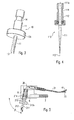
- the exact configuration of the diagnostic probe 10 may be the perspective Representation in Fig. 3 are taken. It is a probe for Examination of interdental spaces. Essential element of the probe 10 is a elongated light wedge 11 made of a transparent material, at the lower end of the Excitation radiation A coupled and on the tooth area to be examined is directed. As a material for the light wedge 11, for example, plastic or Sapphire can be used, being plastic in terms of lower risk of breakage and manufacturing costs is advantageous, but disadvantages with regard to Wear and the resulting lifetime has.
- the light should be be coupled laterally to the longitudinal axis of the light wedge 11 to a To allow examination of the interdental spaces.
- the incident light from above is then totally reflected at this slope 13 and laterally decoupled from the light wedge 11. Additionally or alternatively could the slope 13 also be mirrored to achieve the deflection of the light.
- the return of the radiation on the tooth surface resulting Response radiation F occurs in a similar manner in the reverse direction. At first it falls the response radiation laterally into the light wedge 11 and is in turn at the Bevel 13 reflected and thus directed to the front side of the probe 10 and in the Fiber bar 30 coupled. From the end of the fiber rod 30, in turn preferably of a plurality of individual fibers with a diameter of 0.1 mm exists and has a total diameter of about 1.4 mm, then the Response radiation coupled into a light fiber bundle 31, which on the one hand from the or the excitation radiation fiber (s) 23 for the excitation radiation A and the another consists of a detection fiber 41 for transmitting the response radiation F.
- the detection fiber 41 which preferably has a diameter of 0.25 mm has, then the forwarding to a detection device 40, whose closer structure will be described later.
- the task of this Detector 40 is the one returned from the tooth surface To record response radiation, to analyze and based on the measurement result to judge whether one of the aforementioned fluorescent substances at the examined tooth surface is present or not.
- the diagnostic probe 10 that it is located in the head area 3 of the Handpiece 1 is mounted rotatable by 360 °, so that the handpiece 1 very flexible the teeth to be examined can be introduced.
- the probe 10 is with latched to the head portion 3 of the handpiece 3 and can in a very simple manner -. for cleaning purposes or for replacement by another probe - taken become.
- a cylindrical guide 8 for the probe 10 and a locking pin 6 is provided with the Help a spring 7 presses against the probe 10 and thus used in the Position within the guide 8 stops.
- the front ball segment of the locking pin is provided in the head region 3 of the Handpiece 1.
- the holder 12 itself has an elongated bore, in which is the light wedge 11 is inserted, with the possibility of the light wedge 11th replaced.
- a defined arrangement or orientation of the light wedge 11 within the holder 12 is ensured by a nose 11 a, which with a corresponding recess cooperates in the holder 12.
- the diagnostic probe 10 compared to the Handpiece longitudinal axis not at right angles, but preferably slightly is held obliquely at an angle ⁇ of about 80 °. It turned out that This makes a particularly ergonomic handling of the invention Inspection device is achieved.
- the detachable mounting of the probe 10 brings on the one hand the advantage that the Probe 10 removed after each examination and separated from the rest Components of the handpiece 1 can be cleaned and disinfected. On the other hand, there is also the advantage that the probe 10 easily replaced and by a differently designed probe can be replaced. There is thus the Possibility to provide differently shaped probes depending on the location or Surface design of the examined tooth site can be configured.
- FIGS. 4 and 5 show, by way of example, two others in the case of the invention Diagnostic system used probes.
- the probe shown in Fig. 4 110 is a so-called Parosonde, which is used to study Periodontal pockets and in particular for locating subgingival Concrements to tooth roots is provided.
- the parison 110 has no bevel on the probe tip but just flattened at the very end. This will be a very slim light output achieved with a small diameter, so that the Exciting radiation directed very concentrated on a site to be examined can be. A light emission at the periphery of the probe 110, however, is not intended.
- the parison 110 thus again consists of an elongated wedge of light 111 made of a light-conducting material having a front light exit tip 113, wherein the light wedge 111 by a holder 112 with a disc-shaped attachment 112a is held, which in the rear area again the circumferential recess 114, via which a locking is achieved with the handpiece has.
- a third probe 210 for carrying out investigations in the fissure area - ie to examine the chewing surfaces of teeth or smooth surfaces or Tooth outer surfaces - is shown in Fig. 5.
- Central element of this third probe 210 is a cylindrical light rod 211, which in its front end portion a frusto-conical end 213, via the light in the longitudinal direction of the probe 210 is discharged and coupled in the opposite direction.
- this third Probe 210 has the required for releasable locking with the handpiece 1 Recess 214 and the holder 212 with the disc-shaped attachment 212 a. It should be noted, however, that in the probes of Figs. 4 and 5, the rotation is not is absolutely necessary, since a light leakage or light entry anyway in Direction of the longitudinal axis of the probe 110 and 210, respectively.
- Fig. 6 is, however, there is also the possibility to dispense with this fiber rod 30 and instead, the two bundles 23 for the excitation radiation and 41 for the To combine response radiation to a common fiber bundle 31, which extends to the front of the probe 10 and directly into this light coupled or light from this decoupled.
- the common fiber bundle 31 exists thus on the one hand from fibers for the transmission of the excitation radiation A and on the other hand, fibers for the transmission of the response radiation F.
- the fibers for the excitation radiation A centrally and concentric with the fibers for the response radiation F to surround.
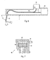
- a light guide 41 opens into a device 40 for Detection of the response radiation, whose detailed embodiment now with reference to FIG. 7 will be explained.
- the central element of the detection unit 40 is a photodiode 42, which the Response radiation F detected and in an electrical signal according to the intensity of Response radiation F implements.
- the amount of intensity of the response radiation F gives finally, information on whether at the examined tooth tissue area fluorescent materials are present or not.
- the photodiode 42 in a housing 43rd integrated, which is arranged as a whole in the handpiece 1.
- a side of the Housing 43 projecting pin 44 is used for locking on a circuit board within the Handpiece 1.
- the front end is of the housing 43 is provided with a cylindrical opening 45 into which the Fiber optic bundle is inserted. Through the opening 45, the bundle is so held that the light is directed to the photodiode 42 directly. About that In addition, a snap closure is provided at the opening 45 through which the Fiber bundle 41 is also held firmly in the desired position. Finally, in the housing 43 is still a filter 46 integrated, which for the evaluation of the Response radiation F filters out non-relevant wavelength ranges. It will thus ensures that only such light detected and evaluated by the photodiode 42 which is also relevant for the diagnosis of fluorescent materials.
- the filter 46 is for example designed such that only radiation with wavelengths above 680 nm is transmitted.
- the arrangement shown in Fig. 7 is thus not only extremely compact but at the same time ensures the most effective and accurate evaluation possible Response radiation F.
- FIGS. 8 and 9 show, in addition to FIGS. 2a-c and 7, two others Variants for transmitting the excitation and response radiation. It is in the Variant according to FIG. 8 in turn initially provided a fiber bundle 31, which intended both for the transmission of excitation and the response radiation is. However, the fiber bundle 31 then does not split into two separate bundles for the different radiations on but is up with its rear end a splitter mirror 32 or beam splitter directed, the partially permeable and for the Coupling and decoupling of the excitation and response radiation is responsible.
- divider mirror 32 consists of a material which on the one hand the reflected by the photodiode 20 excitation radiation A and on the other the radiation of interest F F unhindered in the direction of the Detecting unit 40 passes.
- the positions of the Photodiode 20 and the detection unit 40 are also exchanged, if the Splitter mirror 32 is coated accordingly, so for the corresponding Wavelengths is suitably permeable or reflective.
- Fiber bundle 31 is in this case by a deflection mirror 33 in the head region of Handpiece 1 replaced, which deflects the light in a suitable manner.
- focusing lens 34 ensures that the Light also in the desired bundled way on the different optical Elements hits.
- the coupling and decoupling of the excitation and response radiation takes place again with the help of the arranged in the rear region of the handpiece Splitter mirror 32.
- the inventive solution to this problem is the handpiece 1 with a sleeve, which is removed from the handpiece and sterilized separately can be, with the sleeve itself being that part which is in contact with the patient Contact us and use as few electronic components as possible.
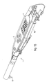
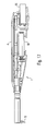
- Fig. 10 shows the handpiece with the already removed sleeve 50 in the removed state is shown in Fig. 11.
- the sleeve 50 envelops it in particular the front end region of the handpiece 1 completely, so that it is ensured that only the sleeve 50 is in contact with the patient, not however, the internal components of the assay device.
- the sleeve 50 can then be deducted from the front or on the handpiece body. 2 be pushed, with the aid of a detent pin 50a at the rear end of the Sleeve 50 a secure hold between sleeve 50 and handpiece body 2 is achieved.
- the Halt between both elements is further enhanced by an O-ring 50b, the is arranged in the central region of the handpiece body 2 and beyond ensures a seal of the rear handpiece area.
- the sleeve 50 is made of a material which is easy to clean and sterilize. Furthermore, the essential electronic Components of the handpiece 1 according to the invention - as already mentioned - not in the sleeve 50 but arranged in the remaining portion of the handpiece 1, the does not need to be sterilized.
- a ring switch 5 is provided, which is also in attached sleeve 50th can be operated and despite everything by the sterilization process is not damaged becomes.
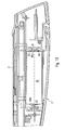
- the inventive design of the ring switch is shown in FIGS. 12 and 13 shown in more detail.
- the switch consists of two components that on the one hand or in the sleeve 50 and the other are arranged inside the handpiece.
- An essential part of the switch in the interior of the handpiece 1 is a electrical line 52 which is interrupted at the location of the ring switch.
- the Lines end here in each case on a cylindrical plastic sleeve 53, the two spaced-apart circumferential tracks 53a (which also in Fig. 10), which through a gap 53b from each other are separated.
- the line 52 is closed and thus an activation signal be generated for the examination device.
- sleeve plate-shaped contacts 51 are provided which components of a switching cap in Form of a flexible ring 5, which is part of the sleeve 50 and in the patch State of the sleeve 50 on the handpiece 1 in the region of the conductor tracks 53a is arranged.
- a switching cap in Form of a flexible ring 5 which is part of the sleeve 50 and in the patch State of the sleeve 50 on the handpiece 1 in the region of the conductor tracks 53a is arranged.
- separate contact pills 51 would also be the possibility of conductive
- vulcanize for example.
- a suitable material would be for this
- offer carbon which can be either in the form of individual Contacting areas or as an annular contacting structure in the sleeve 50th could be incorporated.
- the sleeve 50 at least in Area of the ring switch 5 completely made of a flexible but conductive material to build.
- the handpiece 1 also has a loudspeaker, over which the current measurement result can be displayed acoustically. For example This could be the intensity of the measured response radiation by a in Frequency and / or volume changing signal can be displayed.
- the receptacle for the battery 60 or batteries for power supply is such designed so that accidental wrong insertion of the batteries 60 is prevented.
- This reverse polarity protection is shown in Fig. 16 and has as an essential element in the region that is for contacting the positive pole 60 a of the battery 60 is provided, a contact surface 63 which has a circular recess 64th contains. The positive pole 60 a can pass through this recess 64 and the Contact connection 61.
- the battery 60 in opposite Direction no contact would be made because the negative Terminal 60b of the battery 60 is not through the opening 64 of the contact surface 63rd can reach through. Damage to the device due to incorrect insertion of the Batteries 60 in the handpiece 1 is thus excluded.
- Handpiece 1 As mentioned above, there is an essential feature of Handpiece 1 according to the invention in that it is completely independent of external facilities can be used. All to carry out the Examination and presentation of the examination results required elements are arranged inside the handpiece 1. In particular, the representation also takes place the measurement result, as will be explained in more detail later, about the handpiece 1 itself.
- a particular advantage of transmitting the data by means of ultrasound is that that provided on the handpiece 1 speaker, the primary for the representation of Measurement results is used, at the same time also used for data transmission can be. This means that on an additional element for data transmission can be omitted and only a suitable control of the speaker must be ensured.
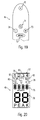
- FIGS. 19 and 20 show that at the Top of the handpiece located control panel 4a for activating certain Functions as well as the display unit 4b for displaying the current function or FIG. 21 shows the concept of operator guidance for schematically illustrates the handpiece 1 according to the invention.
- the control panel 4a consists of a total of five keys, namely a central key 70, a memory button 71, a menu button 72, and two dial buttons 73 and 74.
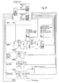
- the function of the individual keys will be described later on the basis of the operating scheme of FIG. 21 explained.
- the display field 4b has a first digital display 75 Representation of the instantaneous measured value, a second display 76 for displaying the Maximum value and a display 77 to display the number of used Probe. Further, six light symbols 78 to 83 are provided, through which the Status in which the handpiece 1 is currently or an action that is currently is performed is displayed.
- the handpiece With the help of the central or multifunction button 70, on the one hand the handpiece fully on and off, in addition, the maximum value reset or an offset correction be performed.
- the function of the memory button 71 depends on whether just the Menu mode is active or not. In the event that the menu is currently not activated has been, by pressing the memory button 71 is a transmission of the current Initiated peak value via the wireless connection to a central processing unit, which is illustrated by the illumination of the light symbol 83. Is located however, the handpiece 1 just in a particular menu item, so is by the Pressing the memory button 71 stores the currently set value and the menu leave.
- the function of the two dial buttons 73 and 74 also depends on whether the menu currently active or not. Inactive menu can be over the wireless connection a signal is transmitted to a central presentation unit, which is a Moving forward in a tooth diagram shown on a display causes. In in the same way, when the menu is not active with the aid of the button 74, a Caused backward movement in the tooth scheme, so that at keys 73 and 74 in This stage can be used as navigation buttons. With the menu active, on the other hand can use the keys 73 and 74 to set the current numerical value of the corresponding Menu item to be set parameters increased or decreased.
- menu key 72 is used to call up a particular menu item, with a rotating selection between the various items.
- the various menu items are adjustment, probe selection, volume, reference value and display mode, the various functions of these menu items being able to be taken from the scheme in FIG. 21.
- the menu item " Adjustment” serves to carry out a comparison of the examination device. After pressing the memory button 71, a zero signal is first recorded for this purpose, which is obtained by directing the measuring probe into free space. Subsequently, the probe is to be directed to a reference body and it is carried out a further measurement, wherein the measurement result obtained in this case is used to equalize the examination device.
- Probe selection can be used to assign a specific number to the currently mounted probe. This is helpful in a later evaluation of the measurement result, since each measurement result is assigned a specific probe.
- the third menu item " Volume” is used to adjust the volume of the measuring signal sent via the loudspeaker.
- reference value it is possible to determine a reference value indicating from which intensity of the measuring signal on the presence of caries is concluded or an acoustic indication of the measurement result takes place.
- the device according to the invention is located in so-called display mode.
- This is in the instantaneous value display 75 at a Activation of the light source for the excitation radiation of the instantaneous measured value represented, which provides information about the intensity of the detected response radiation.
- the peak value display 76 shows the peak value of the current measurement represented by a permanent comparison with the current measured values is determined. The storage of this peak value is therefore advantageous since thereby at a later time of the measurement in a simple way the one Spot can be found again at which the largest collection of one fluorescent substance was diagnosed.
- the user scheme according to the invention is particularly catchy and understandable since it is a uniform operating scheme for each individual menu item.
- the Operation of the examination device according to the invention can thus already after be carried out by non-experienced persons for a short time.
- an examination device for Examination of tooth surfaces indicated, which is characterized by its special easy handling, but at the same time also the requirements adequate hygiene.
Landscapes
- Health & Medical Sciences (AREA)
- Life Sciences & Earth Sciences (AREA)
- Heart & Thoracic Surgery (AREA)
- Medical Informatics (AREA)
- Physics & Mathematics (AREA)
- Veterinary Medicine (AREA)
- Biophysics (AREA)
- Pathology (AREA)
- Engineering & Computer Science (AREA)
- Biomedical Technology (AREA)
- Public Health (AREA)
- General Health & Medical Sciences (AREA)
- Molecular Biology (AREA)
- Surgery (AREA)
- Animal Behavior & Ethology (AREA)
- Oral & Maxillofacial Surgery (AREA)
- Audiology, Speech & Language Pathology (AREA)
- Dentistry (AREA)
- Dental Tools And Instruments Or Auxiliary Dental Instruments (AREA)
- Investigating, Analyzing Materials By Fluorescence Or Luminescence (AREA)
- Investigating Or Analysing Materials By Optical Means (AREA)
Priority Applications (1)
| Application Number | Priority Date | Filing Date | Title |
|---|---|---|---|
| EP20100182564 EP2260761A1 (fr) | 2004-05-14 | 2005-05-13 | Dispositif dentaire pour l'examen de charactéristiques optiques dentaires |
Applications Claiming Priority (2)
| Application Number | Priority Date | Filing Date | Title |
|---|---|---|---|
| DE102004024165A DE102004024165A1 (de) | 2004-05-14 | 2004-05-14 | Zahnärztliche Vorrichtung zum Untersuchen der optischen Eigenschaften von Zahngewebe |
| DE102004024165 | 2004-05-14 |
Related Child Applications (1)
| Application Number | Title | Priority Date | Filing Date |
|---|---|---|---|
| EP10182564.4 Division-Into | 2010-09-29 |
Publications (3)
| Publication Number | Publication Date |
|---|---|
| EP1595495A2 true EP1595495A2 (fr) | 2005-11-16 |
| EP1595495A3 EP1595495A3 (fr) | 2005-12-28 |
| EP1595495B1 EP1595495B1 (fr) | 2012-10-31 |
Family
ID=34936509
Family Applications (2)
| Application Number | Title | Priority Date | Filing Date |
|---|---|---|---|
| EP20100182564 Withdrawn EP2260761A1 (fr) | 2004-05-14 | 2005-05-13 | Dispositif dentaire pour l'examen de charactéristiques optiques dentaires |
| EP05010492A Expired - Lifetime EP1595495B1 (fr) | 2004-05-14 | 2005-05-13 | Dispositif dentaire pour l'examen de charactéristiques optiques dentaires |
Family Applications Before (1)
| Application Number | Title | Priority Date | Filing Date |
|---|---|---|---|
| EP20100182564 Withdrawn EP2260761A1 (fr) | 2004-05-14 | 2005-05-13 | Dispositif dentaire pour l'examen de charactéristiques optiques dentaires |
Country Status (4)
| Country | Link |
|---|---|
| US (1) | US7740477B2 (fr) |
| EP (2) | EP2260761A1 (fr) |
| JP (1) | JP4731201B2 (fr) |
| DE (1) | DE102004024165A1 (fr) |
Cited By (1)
| Publication number | Priority date | Publication date | Assignee | Title |
|---|---|---|---|---|
| EP2452613A1 (fr) * | 2010-11-11 | 2012-05-16 | Kaltenbach & Voigt GmbH | Appareil de diagnostic médical, notamment dentaire, doté de moyens destinés à la détection d'image |
Families Citing this family (16)
| Publication number | Priority date | Publication date | Assignee | Title |
|---|---|---|---|---|
| DE102004002929A1 (de) * | 2004-01-14 | 2005-08-04 | Laser- Und Medizin- Technologie Gmbh | Verfahren zur Bestimmung der Farbwahrnehmung bei Mehrschichtsystemen |
| EP2043524B1 (fr) * | 2006-06-23 | 2016-11-02 | Dentsply Canada Ltd. | Appareil et procédé de détection de pathologies dentaires |
| GB2443203B (en) * | 2006-06-26 | 2010-04-07 | Osspray Ltd | Apparatus for detecting infected tissue |
| DE102007036096A1 (de) | 2007-08-01 | 2009-02-05 | Kaltenbach & Voigt Gmbh | Zahnärztliches Handgerät zum Erstellen von Messergebnissen |
| DE102007047068A1 (de) * | 2007-10-01 | 2009-04-02 | Ferton Holding S.A. | Vorrichtung zum Erkennen von bakteriellem Befall im Wurzelkanal von Zähnen |
| DE102007047067A1 (de) * | 2007-10-01 | 2009-04-02 | Ferton Holding S.A. | Vorrichtung zum Erkennen von bakteriellem Befall an Zähnen |
| AU2008357475B2 (en) | 2008-06-04 | 2012-11-01 | Colgate-Palmolive Company | Oral care implement with cavitation system |
| US20100010482A1 (en) * | 2008-06-23 | 2010-01-14 | Ceramoptec Industries Inc. | Enhanced Photodynamic Therapy Treatment and Instrument |
| US8222610B2 (en) | 2009-09-02 | 2012-07-17 | Sirona Dental Systems Gmbh | Auxiliary component for medical device having additional functionality |
| DE102010040415B4 (de) * | 2010-09-08 | 2017-09-21 | Siemens Healthcare Gmbh | Instrument für einen Manipulatorarm eines Endoskopieroboters |
| DE102012216159B4 (de) * | 2012-09-12 | 2016-04-28 | Secopta Gmbh | Messkopfspitze für ein Spektrometer |
| EP3019071B1 (fr) | 2013-07-11 | 2018-08-08 | Koninklijke Philips N.V. | Système de détection de plaque a base de fluorescence à résolution temporelle |
| KR101787721B1 (ko) * | 2015-08-28 | 2017-10-18 | 부산대학교 산학협력단 | 형광스펙트럼을 이용한 초기우식 진단장치 |
| US20180317774A1 (en) * | 2017-05-02 | 2018-11-08 | Covidien Lp | Infection detection devices and methods |
| JP7085955B2 (ja) * | 2018-09-27 | 2022-06-17 | シチズン時計株式会社 | 歯垢検出機能付き電動歯ブラシ |
| KR102700947B1 (ko) * | 2023-10-17 | 2024-08-30 | (주)스마투스코리아 | 광 기반의 구강 진단 장치 |
Citations (3)
| Publication number | Priority date | Publication date | Assignee | Title |
|---|---|---|---|---|
| DE29704185U1 (de) | 1997-03-07 | 1997-04-30 | Kaltenbach & Voigt Gmbh & Co, 88400 Biberach | Vorrichtung zum Erkennen von Karies, Plaque oder bakteriellem Befall an Zähnen |
| DE19709500C1 (de) | 1997-03-07 | 1998-07-23 | Kaltenbach & Voigt | Verfahren und Vorrichtung zum Ermitteln von Karies an Zähnen |
| DE10013210A1 (de) | 2000-03-17 | 2001-09-20 | Kaltenbach & Voigt | Vorrichtung zum Erkennen von Karies, Plaque, bakteriellen Befall, Konkrementen, Zahnstein und anderen fluoreszierenden Substanzen an Zähnen |
Family Cites Families (26)
| Publication number | Priority date | Publication date | Assignee | Title |
|---|---|---|---|---|
| DE3345465A1 (de) * | 1983-12-15 | 1985-06-27 | Siemens AG, 1000 Berlin und 8000 München | Zahnaerztliches diagnosegeraet |
| GB8700061D0 (en) * | 1987-01-05 | 1987-02-11 | Whatman Reeve Angel Plc | Light absorption analyser |
| EP0281813B1 (fr) * | 1987-02-26 | 1990-08-29 | Siemens Aktiengesellschaft | Gainage pour instruments médicaux, surtout dentaires |
| ATE192292T1 (de) * | 1995-06-28 | 2000-05-15 | Koninkl Philips Electronics Nv | Elektrische zahnbürste mit vorrichtung zur lokalisierung von zahnbelag |
| US6254385B1 (en) * | 1997-01-02 | 2001-07-03 | Lj Laboratories, Llc | Apparatus and method for measuring optical characteristics of teeth |
| EP0940029B1 (fr) * | 1996-01-22 | 2004-06-23 | California Institute Of Technology | Matrice de detecteurs actifs de pixels fournissant plusieurs resolutions de resultats |
| US6201880B1 (en) * | 1996-12-31 | 2001-03-13 | Electro-Optical Sciences | Method and apparatus for electronically imaging a tooth through transillumination by light |
| US5921776A (en) * | 1997-03-05 | 1999-07-13 | Heilbrunn; Karl E. | Disposable protective barriers for use with dental instruments |
| DE19709499A1 (de) * | 1997-03-07 | 1998-09-17 | Kaltenbach & Voigt | Zahnärztliche Behandlungsvorrichtung |
| JPH1147166A (ja) * | 1997-08-06 | 1999-02-23 | Ricoh Elemex Corp | 歯垢検出器 |
| AU6452698A (en) * | 1997-11-03 | 1999-05-24 | Minnesota Mining And Manufacturing Company | Hand-held intraoral curing apparatus |
| JPH11192207A (ja) * | 1997-11-07 | 1999-07-21 | Matsushita Electric Ind Co Ltd | ビデオスコープおよび携帯収納ケース |
| GB9810471D0 (en) * | 1998-05-16 | 1998-07-15 | Helmet Hund Gmbh | Toothbrush |
| JP2000014638A (ja) * | 1998-06-27 | 2000-01-18 | Morita Mfg Co Ltd | 歯科診断システム |
| US6525819B1 (en) * | 1998-09-02 | 2003-02-25 | Pocketspec Technologies Inc. | Colorimeter for dental applications |
| US6095811A (en) * | 1999-01-27 | 2000-08-01 | Welch Allyn, Inc. | Gripping handle for diagnostic instrument |
| US7099732B2 (en) * | 1999-03-29 | 2006-08-29 | Genex Technologies, Inc. | Sanitary sleeve or tip for intra-oral three-dimensional camera |
| US6094272A (en) * | 1999-06-30 | 2000-07-25 | Keyence Corporation | Color discrimination system |
| US6341957B1 (en) | 1999-11-27 | 2002-01-29 | Electro-Optical Sciences Inc. | Method of transillumination imaging of teeth |
| US7050168B2 (en) * | 1999-12-08 | 2006-05-23 | X-Rite, Incorporated | Optical measurement device and related process |
| US6276933B1 (en) * | 2000-03-21 | 2001-08-21 | Ivan Melnyk | Dental translucency analyzer and method |
| US6398424B1 (en) * | 2000-06-30 | 2002-06-04 | Photonage, Inc. | Rugged type multi-channel optical connector |
| US6798517B2 (en) * | 2000-09-28 | 2004-09-28 | Color-Spec Technologies, Inc. | Handheld, portable color measuring device with display |
| US6674530B2 (en) * | 2001-04-27 | 2004-01-06 | International Business Machines Corporation | Portable colorimeter |
| JP2004089237A (ja) * | 2002-08-29 | 2004-03-25 | Matsushita Electric Ind Co Ltd | 歯観察装置 |
| DE102004001856B4 (de) * | 2003-01-14 | 2019-05-23 | J. Morita Mfg. Corp. | Bilderstellungsgerät für Diagnosezwecke |
-
2004
- 2004-05-14 DE DE102004024165A patent/DE102004024165A1/de not_active Withdrawn
-
2005
- 2005-05-11 US US11/126,768 patent/US7740477B2/en not_active Expired - Fee Related
- 2005-05-13 EP EP20100182564 patent/EP2260761A1/fr not_active Withdrawn
- 2005-05-13 EP EP05010492A patent/EP1595495B1/fr not_active Expired - Lifetime
- 2005-05-13 JP JP2005140877A patent/JP4731201B2/ja not_active Expired - Fee Related
Patent Citations (3)
| Publication number | Priority date | Publication date | Assignee | Title |
|---|---|---|---|---|
| DE29704185U1 (de) | 1997-03-07 | 1997-04-30 | Kaltenbach & Voigt Gmbh & Co, 88400 Biberach | Vorrichtung zum Erkennen von Karies, Plaque oder bakteriellem Befall an Zähnen |
| DE19709500C1 (de) | 1997-03-07 | 1998-07-23 | Kaltenbach & Voigt | Verfahren und Vorrichtung zum Ermitteln von Karies an Zähnen |
| DE10013210A1 (de) | 2000-03-17 | 2001-09-20 | Kaltenbach & Voigt | Vorrichtung zum Erkennen von Karies, Plaque, bakteriellen Befall, Konkrementen, Zahnstein und anderen fluoreszierenden Substanzen an Zähnen |
Cited By (1)
| Publication number | Priority date | Publication date | Assignee | Title |
|---|---|---|---|---|
| EP2452613A1 (fr) * | 2010-11-11 | 2012-05-16 | Kaltenbach & Voigt GmbH | Appareil de diagnostic médical, notamment dentaire, doté de moyens destinés à la détection d'image |
Also Published As
| Publication number | Publication date |
|---|---|
| JP2005324032A (ja) | 2005-11-24 |
| DE102004024165A1 (de) | 2005-12-01 |
| EP1595495B1 (fr) | 2012-10-31 |
| EP1595495A3 (fr) | 2005-12-28 |
| JP4731201B2 (ja) | 2011-07-20 |
| US7740477B2 (en) | 2010-06-22 |
| US20050255424A1 (en) | 2005-11-17 |
| EP2260761A1 (fr) | 2010-12-15 |
Similar Documents
| Publication | Publication Date | Title |
|---|---|---|
| EP1595495B1 (fr) | Dispositif dentaire pour l'examen de charactéristiques optiques dentaires | |
| DE60316699T2 (de) | Dentalgerät zur untersuchung der zahnoberfläche | |
| DE102013006636B4 (de) | Dentalkamera zur Kariesdetektion | |
| DE19709500C1 (de) | Verfahren und Vorrichtung zum Ermitteln von Karies an Zähnen | |
| DE19755169C2 (de) | Periodontaltaschenmeßgerät | |
| EP0862896B1 (fr) | Dispositif pour la détection des caries, de la plaque ou de l'attaque bactérienne dentaire | |
| DE68910839T2 (de) | Elektronische zahnärztliche Videokamera und zahnärztliches Instrument. | |
| DE10236175B4 (de) | Lasersystem mit fasergebundener Kommunikation | |
| DE69738205T2 (de) | Umhüllung für Aufnehmer zur Wiedererkennung von Gewebetypen | |
| EP1136034A1 (fr) | Dispositif de détection de substances dentaires fluorescentes | |
| DE29705934U1 (de) | Diagnose- und Behandlungsvorrichtung für Zähne | |
| EP2452614B1 (fr) | Système de médecine dentaire destiné à transilluminer des dents | |
| EP0862899A2 (fr) | Dispositif de traitement dentaire | |
| EP2452612A1 (fr) | Appareil de médecine dentaire doté d'un instrument manuel et d'une source lumineuse | |
| EP2074940A1 (fr) | Dispositif de traitement ou d'examen dentaire | |
| EP3213675A1 (fr) | Dispositif et procédé de tomographie optique par cohérence double (otc) sur l'oreille moyenne humaine | |
| EP0688180A1 (fr) | Instrument de diagnostic dentaire | |
| EP1480570B1 (fr) | Instrument dentaire a main | |
| DE10043749A1 (de) | Zahnmedizinisches Handstück | |
| DE102006041020B4 (de) | System zum Transilluminieren von Zähnen und Kopfstück hierfür | |
| EP2452615A1 (fr) | Système de médecine dentaire destiné à transilluminer des dents | |
| DE20209441U1 (de) | Vorrichtung zum Erkennen von bakteriellem Befall an Zähnen | |
| DE60018736T2 (de) | Optisches biopsiesystem | |
| DE102004024164A1 (de) | Zahnärztliches System zum Untersuchen der optischen Eigenschaften von Zahngewebe mit optischer Untersuchungsvorrichtung und Abgleicheinrichtung | |
| DE102010043794A1 (de) | Medizinisches, insbesondere zahnmedizinisches Diagnosegerät mit Mitteln zur Bilderfassung |
Legal Events
| Date | Code | Title | Description |
|---|---|---|---|
| PUAI | Public reference made under article 153(3) epc to a published international application that has entered the european phase |
Free format text: ORIGINAL CODE: 0009012 |
|
| PUAL | Search report despatched |
Free format text: ORIGINAL CODE: 0009013 |
|
| AK | Designated contracting states |
Kind code of ref document: A2 Designated state(s): AT BE BG CH CY CZ DE DK EE ES FI FR GB GR HU IE IS IT LI LT LU MC NL PL PT RO SE SI SK TR |
|
| AX | Request for extension of the european patent |
Extension state: AL BA HR LV MK YU |
|
| AK | Designated contracting states |
Kind code of ref document: A3 Designated state(s): AT BE BG CH CY CZ DE DK EE ES FI FR GB GR HU IE IS IT LI LT LU MC NL PL PT RO SE SI SK TR |
|
| AX | Request for extension of the european patent |
Extension state: AL BA HR LV MK YU |
|
| RAP1 | Party data changed (applicant data changed or rights of an application transferred) |
Owner name: KALTENBACH & VOIGT GMBH |
|
| 17P | Request for examination filed |
Effective date: 20060616 |
|
| AKX | Designation fees paid |
Designated state(s): AT CH DE FR IT LI |
|
| 17Q | First examination report despatched |
Effective date: 20070219 |
|
| GRAP | Despatch of communication of intention to grant a patent |
Free format text: ORIGINAL CODE: EPIDOSNIGR1 |
|
| GRAS | Grant fee paid |
Free format text: ORIGINAL CODE: EPIDOSNIGR3 |
|
| GRAA | (expected) grant |
Free format text: ORIGINAL CODE: 0009210 |
|
| AK | Designated contracting states |
Kind code of ref document: B1 Designated state(s): AT CH DE FR IT LI |
|
| REG | Reference to a national code |
Ref country code: CH Ref legal event code: NV Representative=s name: BOHEST AG Ref country code: CH Ref legal event code: EP |
|
| REG | Reference to a national code |
Ref country code: AT Ref legal event code: REF Ref document number: 581552 Country of ref document: AT Kind code of ref document: T Effective date: 20121115 |
|
| REG | Reference to a national code |
Ref country code: DE Ref legal event code: R096 Ref document number: 502005013217 Country of ref document: DE Effective date: 20121227 |
|
| PG25 | Lapsed in a contracting state [announced via postgrant information from national office to epo] |
Ref country code: IT Free format text: LAPSE BECAUSE OF FAILURE TO SUBMIT A TRANSLATION OF THE DESCRIPTION OR TO PAY THE FEE WITHIN THE PRESCRIBED TIME-LIMIT Effective date: 20121031 |
|
| PLBE | No opposition filed within time limit |
Free format text: ORIGINAL CODE: 0009261 |
|
| STAA | Information on the status of an ep patent application or granted ep patent |
Free format text: STATUS: NO OPPOSITION FILED WITHIN TIME LIMIT |
|
| 26N | No opposition filed |
Effective date: 20130801 |
|
| REG | Reference to a national code |
Ref country code: DE Ref legal event code: R097 Ref document number: 502005013217 Country of ref document: DE Effective date: 20130801 |
|
| REG | Reference to a national code |
Ref country code: CH Ref legal event code: PCAR Free format text: NEW ADDRESS: HOLBEINSTRASSE 36-38, 4051 BASEL (CH) |
|
| REG | Reference to a national code |
Ref country code: FR Ref legal event code: PLFP Year of fee payment: 12 |
|
| REG | Reference to a national code |
Ref country code: FR Ref legal event code: PLFP Year of fee payment: 13 |
|
| REG | Reference to a national code |
Ref country code: FR Ref legal event code: PLFP Year of fee payment: 14 |
|
| PGFP | Annual fee paid to national office [announced via postgrant information from national office to epo] |
Ref country code: FR Payment date: 20190524 Year of fee payment: 15 |
|
| PGFP | Annual fee paid to national office [announced via postgrant information from national office to epo] |
Ref country code: CH Payment date: 20190524 Year of fee payment: 15 |
|
| PGFP | Annual fee paid to national office [announced via postgrant information from national office to epo] |
Ref country code: AT Payment date: 20190523 Year of fee payment: 15 |
|
| REG | Reference to a national code |
Ref country code: DE Ref legal event code: R082 Ref document number: 502005013217 Country of ref document: DE Representative=s name: MITSCHERLICH, PATENT- UND RECHTSANWAELTE PARTM, DE Ref country code: DE Ref legal event code: R081 Ref document number: 502005013217 Country of ref document: DE Owner name: KAVO DENTAL GMBH, DE Free format text: FORMER OWNER: KALTENBACH & VOIGT GMBH, 88400 BIBERACH, DE |
|
| REG | Reference to a national code |
Ref country code: AT Ref legal event code: MM01 Ref document number: 581552 Country of ref document: AT Kind code of ref document: T Effective date: 20200513 |
|
| PG25 | Lapsed in a contracting state [announced via postgrant information from national office to epo] |
Ref country code: CH Free format text: LAPSE BECAUSE OF NON-PAYMENT OF DUE FEES Effective date: 20200531 Ref country code: AT Free format text: LAPSE BECAUSE OF NON-PAYMENT OF DUE FEES Effective date: 20200513 Ref country code: LI Free format text: LAPSE BECAUSE OF NON-PAYMENT OF DUE FEES Effective date: 20200531 |
|
| PG25 | Lapsed in a contracting state [announced via postgrant information from national office to epo] |
Ref country code: FR Free format text: LAPSE BECAUSE OF NON-PAYMENT OF DUE FEES Effective date: 20200531 |
|
| PGFP | Annual fee paid to national office [announced via postgrant information from national office to epo] |
Ref country code: DE Payment date: 20240319 Year of fee payment: 20 |
|
| REG | Reference to a national code |
Ref country code: DE Ref legal event code: R071 Ref document number: 502005013217 Country of ref document: DE |