EP1593644B1 - Flurförderzeug mit Kolben-Zylinder-Anordnung und verbesserter Zylinderlagerung - Google Patents
Flurförderzeug mit Kolben-Zylinder-Anordnung und verbesserter Zylinderlagerung Download PDFInfo
- Publication number
- EP1593644B1 EP1593644B1 EP05009845.8A EP05009845A EP1593644B1 EP 1593644 B1 EP1593644 B1 EP 1593644B1 EP 05009845 A EP05009845 A EP 05009845A EP 1593644 B1 EP1593644 B1 EP 1593644B1
- Authority
- EP
- European Patent Office
- Prior art keywords
- cylinder
- bearing
- component
- industrial truck
- piston
- Prior art date
- Legal status (The legal status is an assumption and is not a legal conclusion. Google has not performed a legal analysis and makes no representation as to the accuracy of the status listed.)
- Expired - Lifetime
Links
- 238000006073 displacement reaction Methods 0.000 claims description 9
- 230000015572 biosynthetic process Effects 0.000 claims description 4
- 230000033001 locomotion Effects 0.000 description 24
- 239000012530 fluid Substances 0.000 description 4
- 238000004519 manufacturing process Methods 0.000 description 4
- 230000001447 compensatory effect Effects 0.000 description 2
- 230000008878 coupling Effects 0.000 description 2
- 238000010168 coupling process Methods 0.000 description 2
- 238000005859 coupling reaction Methods 0.000 description 2
- 241001416181 Axis axis Species 0.000 description 1
- 230000000712 assembly Effects 0.000 description 1
- 238000000429 assembly Methods 0.000 description 1
- 230000005540 biological transmission Effects 0.000 description 1
- 238000013016 damping Methods 0.000 description 1
- 230000007423 decrease Effects 0.000 description 1
- 238000009434 installation Methods 0.000 description 1
- 239000002184 metal Substances 0.000 description 1
- 230000002093 peripheral effect Effects 0.000 description 1
- 230000000284 resting effect Effects 0.000 description 1
- 230000009897 systematic effect Effects 0.000 description 1
- 238000003466 welding Methods 0.000 description 1
Images
Classifications
-
- B—PERFORMING OPERATIONS; TRANSPORTING
- B66—HOISTING; LIFTING; HAULING
- B66F—HOISTING, LIFTING, HAULING OR PUSHING, NOT OTHERWISE PROVIDED FOR, e.g. DEVICES WHICH APPLY A LIFTING OR PUSHING FORCE DIRECTLY TO THE SURFACE OF A LOAD
- B66F9/00—Devices for lifting or lowering bulky or heavy goods for loading or unloading purposes
- B66F9/06—Devices for lifting or lowering bulky or heavy goods for loading or unloading purposes movable, with their loads, on wheels or the like, e.g. fork-lift trucks
- B66F9/075—Constructional features or details
- B66F9/20—Means for actuating or controlling masts, platforms, or forks
- B66F9/22—Hydraulic devices or systems
-
- B—PERFORMING OPERATIONS; TRANSPORTING
- B66—HOISTING; LIFTING; HAULING
- B66F—HOISTING, LIFTING, HAULING OR PUSHING, NOT OTHERWISE PROVIDED FOR, e.g. DEVICES WHICH APPLY A LIFTING OR PUSHING FORCE DIRECTLY TO THE SURFACE OF A LOAD
- B66F9/00—Devices for lifting or lowering bulky or heavy goods for loading or unloading purposes
- B66F9/06—Devices for lifting or lowering bulky or heavy goods for loading or unloading purposes movable, with their loads, on wheels or the like, e.g. fork-lift trucks
- B66F9/075—Constructional features or details
- B66F9/08—Masts; Guides; Chains
Definitions
- the present invention relates to an industrial truck with a piston-cylinder arrangement, comprising a cylinder and a retractable and retractable in this piston, as a drive and / or leadership of a first component for movement relative to a second component, in particular as a drive of components a mast, wherein the piston is associated with a component assigned to it: first or second component, for transmitting power and wherein the cylinder is mounted on a cylinder bearing of the other, the cylinder associated component and coupled for transmitting power therewith.
- piston-cylinder arrangements are used as drives and / or as a guide of an extension and a retraction movement of lifting frame relative to truck frame fixed uprights.
- the cylinder is usually connected to at least one bearing point as rigid as possible with the component overlying him.
- misalignment means that piston longitudinal axis and cylinder longitudinal axis are not ideally coaxial, but offset slightly in mutually orthogonal to the cylinder longitudinal axis direction offset direction to each other and / or slightly tilted about an axis of rotation orthogonal to the cylinder axis axis.
- misalignments affect especially in far out of the cylinder extended piston, since the piston can be performed more accurately through the cylinder, the longer the piston is still in the cylinder piston line.
- the WO 81/02290 A1 discloses a bearing point on hydraulic cylinders used to laterally adjust the position of forks of a forklift of a forklift so that different distances of the tines are possible.
- a pivotable in two directions bearing is provided, which is designed with a convex Kalottenabêt on the cylinder and a corresponding concave counterpart on the cylinder bearing.
- the movable spherical bearing surface extends substantially in the longitudinal direction of the cylinder.
- the DE 1 556 601 A1 discloses a lift truck with an extendable mast, wherein the lower end of the lift cylinder is supported with a spherical cap-shaped part in a ball socket-shaped part of the mast. In this case, means are provided with which the ball cap elastic in the ball socket is pressed. The power transmission happens in the central area of the ball cap and ball socket.
- Object of the present invention is therefore to provide an industrial truck of the type mentioned, in which a cylinder of a piston-cylinder assembly overlapping truck component is less heavily loaded.
- the cylinder closure has a bearing configuration, which protrudes radially outward relative to the cylinder tube along the entire circumference of the cylinder closure, that a support surface also protrudes beyond the cylinder circumference and that the support surface in the retraction of the piston under a is arranged slightly different from the perpendicular to the cylinder axis angle to the bearing design.
- the cylinder can make a compensating movement in a direction in which shape or / and position deviations from the ideal shape, such as misalignment between piston and Cylinder, to be reduced, which also makes an area the piston opening of the cylinder decreases to this exerted support torque.
- This support moment is in fact proportional in its amount to the amount of misalignment.
- the relative amount of shape and / or position inaccuracies is reduced by a compensatory movement, as is made possible by the cylinder bearing according to the invention.
- the cylinder driven by the force acting on him from the extended piston support torque, move in a direction in which this exerted on him support torque is smaller, so that the truck with the movably mounted cylinder within certain limits, a self-optimizing system represents.
- a separate control for moving the cylinder in a suitable direction is not required.
- the piston-cylinder arrangement is preferably a hydraulic drive which is suitable for lifting and / or lowering large loads.
- the cylinder has a closed longitudinal end and a longitudinal end with a piston opening, wherein the cylinder bearing supports the cylinder in the region of its longitudinal end with piston opening to advantageously avoid excessive cylinder deformation. Since a seal is provided on the piston opening, which seals the piston opening against the ingress of dirt into the cylinder chamber and, if necessary, against the escape of hydraulic fluid, here is a touch contact exists between the piston and cylinder, by which forces are introduced from the piston into the cylinder. These forces can less lead to a deformation of the cylinder, the closer the cylinder bearing of the piston opening.
- the cylinder bearing is provided such that the piston opening is not located more than 20% of the total length of the cylinder away from the cylinder bearing. More preferably, the distance of the piston opening should not exceed 10% of the total length of the cylinder. Particularly high forces can be absorbed without appreciable deformation of the cylinder, if the piston opening is not located more than 5% of the total length of the cylinder away from the cylinder bearing.
- a movement of the cylinder and the cylinder bearing relative to one another only denotes a slight local relative movement in the region of the cylinder bearing.
- the relative movement of the cylinder and cylinder bearing at the location of the cylinder bearing should not preclude, for example, that the cylinder is mounted at a further bearing point on its associated component or on another component.
- This additional bearing point of the cylinder can be a loose bearing point or even a rigid bearing point, so that in the latter case the local mobility of the cylinder in the range of the cylinder bearing discussed here is adjusted relative to this essentially by a deformation of the cylinder.
- the cylinder can be provided such that it relative to the cylinder bearing in at least one orthogonal to the cylinder longitudinal axis direction of displacement, preferably in two both to each other and to Cylinder longitudinal axis direction orthogonal displacement directions, is displaceable.
- the cylinder may be used to reduce tilting Cylinder and piston longitudinal axis relative to each other also be supported on the cylinder bearing so that it is tiltable relative to the cylinder bearing by at least one to the cylinder longitudinal axis orthogonal tilt axis, preferably two mutually orthogonal to each other and to the cylinder axis tilt axes.
- the latter variant is preferable to the first-mentioned possibility of displaceability of the cylinder relative to the cylinder bearing, because on the one hand with slight movements, which is here a Ausretesverkippung causes a significant reduction of the forces acting on the cylinder bearing due to a previously discussed longitudinal axis offset forces on the cylinder and on the other hand, a bearing with a tiltability of the cylinder relative to the cylinder bearing can be made stiffer than a cylinder bearing with a relative to this displaceable cylinder.
- a tiltability of the cylinder relative to the cylinder bearing if at least one of the surfaces: bearing surface and cylinder bearing surface, at least in the region of the engagement by at least one orthogonal to the cylinder longitudinal axis orthogonal axis of curvature is convexly curved.
- the support surface and / or the cylinder bearing surface may be formed here, for example, as a cylinder jacket part surface.
- both surfaces are convexly curved or that one of the surfaces is flat.
- tiltability or rotatability about at least two tilt axes orthogonal to each other and to the cylinder longitudinal axis direction can be obtained by the support surface and cylinder surface being convexly curved only about an axis of curvature orthogonal to the cylinder longitudinal axis direction, but the axis of curvature of the support surface and the axis of curvature of the cylinder bearing surface are orthogonal to one another ,
- such solutions lead to very high surface pressures at the contact point of the bearing surface and cylinder bearing surface, which is less preferred.
- a particularly good possibility for compensating manufacturing and / or assembly errors can be obtained if at least one of the surfaces: bearing surface and cylinder bearing surface, at least in the region of the engagement engagement convexly curved about two orthogonal to each other and to the cylinder axis direction orthogonal axes of curvature is.
- the cylinder can be tilted or rotated relative to the cylindrical bearing about any tilt axis orthogonal to the cylinder longitudinal axis direction.
- the support surface or / and the cylinder bearing surface may be barrel-shaped at least in sections, so that different radii of curvature are assigned to different tilt axes, which is can lead to a preferential tilting axis.
- This may be desirable if a preferred compensation movement is known, since then still a compensating tilting movement about a tilt axis orthogonal to the preferred tilting axis is possible, but a difficult tilting always allows an increase in the bearing stiffness.
- a universal possibility of a compensatory tilting movement which can be executed under any conditions around any tilt axis orthogonal to the cylinder longitudinal axis direction, is advantageously obtained when the at least one convexly curved surface is spherical-cap-shaped.
- the radius of the spherical cap corresponds to the distance of the curved surface from the further clamping, since then the relative movement of the cylinder and cylinder bearings can take place with only a very small deformation of the cylinder.
- Improved guidance of the relative tilting movement of cylinder and cylinder bearing can be obtained by one of the surfaces: bearing surface and cylinder bearing surface being convexly curved at least in the region of the abutment engagement by at least one axis of curvature orthogonal to the cylinder longitudinal axis direction and the other surface: cylinder bearing surface and bearing surface, at least in the Area of the abutment engagement is concavely curved by at least one orthogonal to the cylinder longitudinal axis direction of curvature axis.
- the cylinder bearing can be made very robust and thus durable, when the support surface and the cylinder bearing surface are curved so that they lie flat against each other.
- this embodiment namely between the Bearing surface and cylinder bearing surface acting surface pressure very low. It is the smaller, the larger the contact surface between support surface and cylinder bearing surface.
- the bearing surface can be provided as desired on the cylinder.
- the support surface extends along a peripheral portion of the cylinder. A higher load capacity of the support surface while still very efficient use of the available space results when the support surface surrounds the cylinder in the circumferential direction. This also allows a uniform application of force to be supported on the cylinder bearing force in the bearing surface.
- the cylinder may include a cylinder tube and a cylinder closure with piston opening.
- the piston can be very easily introduced into the cylinder. Since the cylinder closure is easier and therefore more cost-effective to machine compared to the cylinder tube due to its substantially smaller size, advantageously the bearing surface can be provided as the at least one at least partially curved surface on the cylinder closure. This applies in particular if the cylinder closure is a separate component at least at the time before its connection to the cylinder tube.
- the piston-cylinder arrangement is generally a hydraulic adjusting device, in which, depending on the desired Auskragin of the piston from the cylinder hydraulic fluid is introduced into the cylinder or discharged therefrom, is from the point of view of a simple installation of the hydraulic lines advantageous if the first component is directly or indirectly fixedly connected to a truck frame and the second component is movably mounted relative to the first component, wherein the cylinder, the first frame-fixed component and the piston is associated with the second movably mounted component.
- the distance of the connection point for hydraulic fluid on the cylinder does not change relative to the truck frame, which on the one hand allows the use of the shortest possible hydraulic lines and on the other hand, the hydraulic lines does not walkthrough movement.
- Even sturdy tubes can be used as hydraulic lines.
- the first component can be a stator and the second component can be a lifting frame.
- the first component may be a frame of an additional stroke and the second component may be a load carrier, in particular a fork carriage, movably mounted thereon.
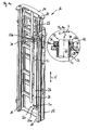
- a mast 10 comprising a mounted on a frame of a truck, not shown stand 12 and a relative to the stator 12 movable lifting frame 14.
- the lifting frame 14 is in guide rails 16 and 18 of the stator 12 for movement relative to the stator 12 in the direction led the double arrow V.
- a piston 22 of the piston-cylinder assembly 20 is fixedly connected at its free longitudinal end with a coupling point 24 of the lifting frame 14.
- the piston 22 can exert both tensile and compressive forces on the lifting frame 14 at the coupling point 24.
- the piston-cylinder arrangement 20 comprises a cylinder 26 with a cylinder tube 28.
- the cylinder longitudinal axis L is parallel to the direction of movement V of the relative movement between the lifting frame 14 and stand 12.
- the cylinder 26 is at its in Fig. 1a lower longitudinal end 26 a held on the stand 12.
- the holder is made via a known floating bearing 30.
- a motion damping can be provided to dampen a relative movement between the longitudinal end 26a and the movable bearing 30.
- the cylinder 26 is mounted slightly movable relative to a cylindrical bearing 34 surrounding it.
- the cylindrical bearing 34 comprises in the example shown a metal plate with a hole which is penetrated by the cylinder 26.
- Fig. 1b the storage at the longitudinal end 26b, on which the piston opening 32 is provided, shown in detail.
- a cylinder lock 36 is inserted and fixedly connected thereto, such as by screwing or by inserting and then welding.
- a seal assembly 38 is provided which surrounds the piston 22 along its circumference and prevents dirt from entering into the interior 40 of the cylinder 26 or hydraulic fluid exits therefrom.
- the cylinder closure 36 has a bearing formation 42, which opposite the cylinder tube 28 protrudes radially outward, and along the entire circumference of the cylinder closure 36.
- the piston 22 and the cylinder 26 surrounding bearing formation 42 has a spherical cap, pointing to the cylinder bearing 34 bearing surface 42a.
- This bearing surface 42a rests on a part-spherical, concave cylinder bearing surface 34a of the cylindrical bearing 34.
- the radii of curvature of the spherical cap surface 42a and the partially spherical recess 34a are chosen to be substantially equal, so that the bearing surface 42a bears flat against the cylindrical bearing surface 34a.
- the cylinder 26 can tilt both about a first axis X orthogonal to the cylinder longitudinal axis L and about a second axis Y orthogonal to the cylinder longitudinal axis L and the first axis X.
- pan or tilt axes X and Y are in Fig. 1b for reasons of space at the top of the Fig. 1b shown. It will be understood, however, that the true tilting axes X and Y pass through the center of curvature of the bearing surface 42a of the bearing closure 42 of the cylinder closure 36 resting on the part-spherical concave cylinder bearing surface 34a for the same relative movement between the bearing surface 42a and cylinder bearing surface 34a.
- the addressed components can therefore be dimensioned correspondingly smaller or, if the dimensions are the same, correspondingly have a longer service life.
- the cylindrical bearing 34 may be formed with a convex curved cylindrical bearing surface and the cylinder 26 with a correspondingly concave bearing surface, but a concave recess on the substantially planar cylinder bearing 34 can be formed easier than a correspondingly convex cylindrical bearing surface.
- a convexly curved bearing surface can be produced in a simple manner by turning.
Landscapes
- Engineering & Computer Science (AREA)
- Transportation (AREA)
- Structural Engineering (AREA)
- Civil Engineering (AREA)
- Life Sciences & Earth Sciences (AREA)
- Geology (AREA)
- Mechanical Engineering (AREA)
- Chemical & Material Sciences (AREA)
- Combustion & Propulsion (AREA)
- Forklifts And Lifting Vehicles (AREA)
- Actuator (AREA)
Description
- Die vorliegende Erfindung betrifft ein Flurförderzeug mit einer Kolben-Zylinder-Anordnung, umfassend einen Zylinder und einen aus diesem ausfahrbaren und in diesen einfahrbaren Kolben, als Antrieb oder/und Führung eines ersten Bauteils zur Bewegung relativ zu einem zweiten Bauteil, insbesondere als Antrieb von Bauteilen eines Hubgerüsts, wobei der Kolben mit einem ihm zugeordneten Bauteil: erstes oder zweites Bauteil, zur Kraftübertragung gekoppelt ist und wobei der Zylinder an einem Zylinderlager des jeweils anderen, dem Zylinder zugeordneten Bauteils gelagert und zur Kraftübertragung mit diesem gekoppelt ist.
- Derartige Flurförderzeuge sind im Stand der Technik allgemein bekannt. So sind beispielsweise Gabelstapler mit teleskopartigen Hubgerüsten bekannt, bei welchen ein Ständer an einem Rahmen des Flurförderzeugs rahmenfest gelagert ist und ein Hubrahmen relativ zum Ständer an diesem verlagerbar gelagert und geführt ist.
- Darüber hinaus sind Flurförderzeuge bekannt, bei welchen alternativ oder zusätzlich zu den oben geschilderten Hubgerüsten weitere relativ bewegbare Bauteile vorgesehen sind, wie etwa Zusatzhübe, Last-, insbesondere Gabelträger, Seitenschübe usw. Bei all diesen genannten Vorrichtungen sind an einem Flurförderzeug ein erstes und ein zweites Bauteil relativ zueinander bewegbar angeordnet.
- Vor allem, aber nicht ausschließlich, werden Kolben-Zylinder-Anordnungen als Antriebe oder/und als Führung einer Ausfahr- und einer Einfahrbewegung von Hubrahmen relativ zu flurförderzeugrahmenfesten Ständern eingesetzt. Um eine möglichst stabile, tragfähige Struktur eines Hubgerüsts am Flurförderzeug zu erhalten, ist der Zylinder in der Regel an wenigstens einer Lagerstelle möglichst starr mit dem ihn lagernden Bauteil verbunden.
- Durch bei Herstellung und Montage übliche Toleranzen sowie durch Verformung unter Last können Form- und Lagerfehler, wie etwa Fluchtungsfehler, an Kolben und Zylinder bzw. zwischen diesen vorhanden sein. "Fluchtungsfehler" bedeutet dabei, dass Kolbenlängsachse und Zylinderlängsachse nicht ideal koaxial sind, sondern in zur Zylinderlängsachsenrichtung orthogonaler Versatzrichtung geringfügig zueinander versetzt oder/und um eine zur Zylinderlängsachsenrichtung orthogonale Drehachse geringfügig verkippt sind. Derartige Fluchtungsfehler wirken sich vor allem bei weit aus dem Zylinder ausgefahrenem Kolben aus, da der Kolben umso genauer durch den Zylinder geführt werden kann, je länger die noch im Zylinder vorhandene Kolbenstrecke ist. Bei weit aus dem Zylinder ausgefahrenem Kolben ist die Führungslänge der noch im Zylinder verbliebenen Kolbenstrecke gering, was bei einer weit von einer Kolbenöffnung des Zylinders entfernt zu haltenden Last zu großen Abstützmomenten am Zylinder in der Nähe der Kolbenöffnung führt. Diese Abstützmomente müssen als Kräfte vom Zylinderlager aufgenommen und vom Bauteil, an welchem das Zylinderlager vorgesehen ist, abgestützt werden.
- Die
WO 81/02290 A1 - Die
DE 1 556 601 A1 offenbart einen Hublader mit einem ausfahrbaren Hubmast, wobei das untere Ende des Hubzylinders mit einem kugelkappenförmigen Teil in einem kugelpfannenförmigen Teil des Hubmastes abgestützt ist. Dabei sind Mittel vorgesehen, mit denen die Kugelkappe elastisch in die Kugelpfanne gedrückt wird. Die Kraftübertragung geschieht dabei im Zentralbereich von Kugelkappe und Kugelpfanne. - Aufgabe der vorliegenden Erfindung ist es daher, ein Flurförderzeug der eingangs genannten Art anzugeben, bei welchem ein den Zylinder einer Kolben-Zylinder-Anordnung lagerndes Flurförderzeug-Bauteil weniger stark belastet ist.
- Diese Aufgabe wird bei einem gattungsgemäßen Flurförderzeug dadurch gelöst, dass der Zylinderverschluss eine Lagerausbildung aufweist, welche gegenüber dem Zylinderrohr längs des gesamten Umfangs des Zylinderverschlusses nach radial außen vorsteht, dass eine Auflagerfläche ebenfalls über den Zylinderumfang hinausragt und dass die Auflagerfläche in Einfahrrichtung des Kolbens unter einem geringfügig von der Senkrechten zu der Zylinderachse abweichenden Winkel an der Lagerausbildung angeordnet ist.
- Ist der Zylinder derart in Anlageeingriff mit dem Zylinderlager, dass er sich relativ zu diesem bewegen kann, kann der Zylinder eine Ausgleichsbewegung in eine Richtung ausführen, in welcher Form- oder/und Lageabweichungen von der Idealform bzw. Ideallage, wie etwa Fluchtungsfehler zwischen Kolben und Zylinder, reduziert werden, wodurch auch ein im Bereich der Kolbenöffnung des Zylinders auf diesen ausgeübtes Abstützmoment abnimmt. Dieses Abstützmoment ist nämlich in seinem Betrag proportional zum Betrag von Fluchtungsfehlern. Der relative Betrag von Form- oder/und Lageungenauigkeiten wird durch eine Ausgleichsbewegung vermindert, wie sie durch die erfindungsgemäße Zylinderlagerung ermöglicht wird.
- Darüber hinaus wird sich der Zylinder, getrieben durch das auf ihn vom ausgefahrenen Kolben einwirkende Abstützmoment, in einer Richtung bewegen, in welcher dieses auf ihn ausgeübte Abstützmoment kleiner wird, so dass das Flurförderzeug mit dem beweglich gelagerten Zylinder in bestimmten Grenzen ein sich selbst optimierendes System darstellt. Eine eigene Steuerung zur Bewegung des Zylinders in einer geeigneten Richtung ist nicht erforderlich.
- Zwar sind beweglich oder gelenkig gelagerte Zylinder, insbesondere Hydraulikzylinder, im Stand der Technik in zahlreichen Anwendungen bekannt. Gerade bei Flurförderzeugen ging die Fachwelt jedoch bisher davon aus, dass eine möglichst exakte Führung von zueinander beweglichen Bauteilen, insbesondere Bauteilen eines Hubsystems, an einem Flurförderzeug durch eine möglichst starr gelagerte Kolben-Zylinder-Anordnung angetrieben oder/und geführt sein soll. Es ist ein Verdienst des Erfinders der vorliegenden Erfindung, sich über dieses Vorurteil der einschlägigen Fachwelt hinweggesetzt zu haben.
- Bei der Kolben-Zylinder-Anordnung handelt es sich bevorzugt um einen hydraulischen Antrieb, welcher zum Heben oder/und Senken großer Lasten geeignet ist. Bei derartigen Kolben-Zylinder-Anordnungen weist der Zylinder ein geschlossenes Längsende und ein Längsende mit einer Kolbenöffnung auf, wobei das Zylinderlager zur vorteilhaften Vermeidung einer übermäßigen Zylinderverformung den Zylinder im Bereich seines Längsendes mit Kolbenöffnung lagert. Da an der Kolbenöffnung eine Dichtung vorgesehen ist, welche die Kolbenöffnung gegen Eintritt von Schmutz in den Zylinderraum sowie ggf. gegen Austritt von Hydraulikflüssigkeit abdichtet, ist hier ein Berührkontakt zwischen Kolben und Zylinder vorhanden, durch welchen Kräfte vom Kolben in den Zylinder eingeleitet werden. Diese Kräfte können umso weniger zu einer Verformung des Zylinders führen, je näher das Zylinderlager der Kolbenöffnung ist. Vorzugsweise ist das Zylinderlager derart vorgesehen, dass die Kolbenöffnung nicht weiter als 20% der Gesamtlänge des Zylinders vom Zylinderlager entfernt angeordnet ist. Noch vorteilhafter sollte die Entfernung der Kolbenöffnung 10% der Gesamtlänge des Zylinders nicht übersteigen. Besonders hohe Kräfte können ohne nennenswerte Verformung des Zylinders aufgenommen werden, wenn die Kolbenöffnung nicht weiter als 5% der Gesamtlänge des Zylinders vom Zylinderlager entfernt angeordnet ist.
- Nachzutragen ist, dass eine Bewegung von Zylinder und Zylinderlager relativ zueinander lediglich eine geringfügige lokale Relativbewegung im Bereich des Zylinderlagers bezeichnet. Die Relativbewegbarkeit von Zylinder und Zylinderlager an der Stelle der Zylinderlagerung soll beispielsweise nicht ausschließen, dass der Zylinder an einer weiteren Lagerstelle an dem ihm zugeordneten Bauteil oder an einem sonstigen Bauteil gelagert ist. Diese weitere Lagerstelle des Zylinders kann eine Loslagerstelle oder sogar eine starre Lagerstelle sein, so dass sich im letztgenannten Fall die lokale Bewegbarkeit des Zylinders im Bereich des hier diskutierten Zylinderlagers relativ zu diesem im Wesentlichen durch eine Verformung des Zylinders einstellt.
- Damit der Zylinder einen Versatz von Zylinderlängsachse und hierzu im Wesentlichen paralleler Kolbenlängsachse durch Bewegung relativ zu dem Zylinderlager reduzieren kann, kann der Zylinder derart vorgesehen sein, dass er relativ zum Zylinderlager in wenigstens einer zur Zylinderlängsachsenrichtung orthogonalen Verlagerungsrichtung, vorzugsweise in zwei sowohl zueinander als auch zur Zylinderlängsachsenrichtung orthogonalen Verlagerungsrichtungen, verschiebbar ist.
- Alternativ oder zusätzlich kann der Zylinder zur Verminderung von Verkippungen von Zylinder- und Kolbenlängsachse relativ zueinander auch derart am Zylinderlager gelagert sein, dass er relativ zum Zylinderlager um wenigstens eine zur Zylinderlängsachsenrichtung orthogonale Kippachse, vorzugsweise um zwei sowohl zueinander als auch zur Zylinderlängsachsenrichtung orthogonale Kippachsen, kippbar ist.
- Letztere Variante ist gegenüber der erstgenannten Möglichkeit einer Verschiebbarkeit des Zylinders relativ zum Zylinderlager zu bevorzugen, da einerseits bei geringfügigen Bewegungen, um die es hier geht, eine Ausgleichsverkippung einen merklichen Abbau auch der auf das Zylinderlager aufgrund eines zuvor diskutierten Längsachsenversatzes auf den Zylinder einwirkenden Kräfte bewirkt und andererseits ein Lager mit einer Verkippbarkeit des Zylinders relativ zum Zylinderlager steifer ausgebildet werden kann als ein Zylinderlager mit einem relativ zu diesem verschiebbaren Zylinder.
- Es ist darüber hinaus leicht einzusehen, dass eine Verlagerbarkeit, sei es nun Verschiebbarkeit oder Verkippbarkeit in zwei zueinander orthogonale Verlagerungsrichtungen bzw. um zwei zueinander orthogonale Kippachsen eine wesentlich größere Möglichkeit der Fehlerkorrektur bietet als eine Verlagerbarkeit mit lediglich einer zur Zylinderlängsachsenrichtung orthogonalen Verlagerungsrichtung bzw. einer zur Zylinderlängsachsenrichtung orthogonalen Kippachse. Ist jedoch, beispielsweise aufgrund einer stets gleichen Krafteinwirkung, eine maßgeblich benötigte Ausgleichsbewegungsrichtung bekannt, kann eine Verlagerbarkeit in lediglich einer Verlagerungsrichtung bzw. um lediglich eine Kippachse vorteilhaft sein, da dieses Lager steifer als ein Lager mit zweiachsiger Verlagerungsmöglichkeit ausgebildet werden kann.
- Mit konstruktiv einfachen und somit kostengünstigen Mitteln kann eine Bewegbarkeit von Zylinder und Zylinderlager relativ zueinander dadurch erhalten werden, dass der Zylinder eine Lagerausbildung mit einer Auflagerfläche aufweist, welche in Anlageeingriff mit einer Zylinderlagerfläche des Zylinderlagers ist.
- Dabei kann weiter mit einfachen Mitteln eine Kippbarkeit des Zylinders relativ zum Zylinderlager erhalten werden, wenn wenigstens eine der Flächen: Auflagerfläche und Zylinderlagerfläche, zumindest im Bereich des Anlageeingriffs um wenigstens eine zur Zylinderlängsachsenrichtung orthogonale Krümmungsachse konvex gekrümmt ist. Die Auflagerfläche oder/und die Zylinderlagerfläche können hier beispielsweise als Zylindermantelteilfläche ausgebildet sein.
- Grundsätzlich ist dabei möglich, dass beide Flächen konvex gekrümmt sind oder dass eine der Flächen eben ist. Weiterhin kann eine Verkippbarkeit bzw. Verdrehbarkeit um wenigstens zwei zueinander und zur Zylinderlängsachsenrichtung orthogonale Kippachsen dadurch erhalten werden, dass Auflagerfläche und Zylinderfläche jeweils nur um eine zur Zylinderlängsachsenrichtung orthogonale Krümmungsachse konvex gekrümmt sind, dass jedoch die Krümmungsachse der Auflagerfläche und die Krümmungsachse der Zylinderlagerfläche orthogonal zueinander liegen. Derartige Lösungen führen jedoch zu sehr hohen Flächenpressungen an der Berührstelle von Auflagerfläche und Zylinderlagerfläche, was weniger bevorzugt ist.
- Wie oben bereits ausgesagt wurde, kann eine besonders gute Möglichkeit zum Ausgleich von Fertigungs- oder/und Montagefehlern erhalten werden, wenn wenigstens eine der Flächen: Auflagerfläche und Zylinderlagerfläche, zumindest im Bereich des Anlageeingriffs um zwei sowohl zueinander als auch zur Zylinderlängsachsenrichtung orthogonalen Krümmungsachsen konvex gekrümmt ist. In diesem Falle kann der Zylinder relativ zum Zylinderlager um jede beliebige zur Zylinderlängsachsenrichtung orthogonale Kippachse gekippt bzw. verdreht werden.
- Beispielsweise kann die Auflagerfläche oder/und die Zylinderlagerfläche zumindest abschnittsweise tonnenförmig ausgeführt sein, so dass unterschiedlichen Kippachsen unterschiedliche Krümmungsradien zugeordnet sind, was zu einer Vorzugskippachse führen kann. Dies kann gewünscht sein, wenn eine Vorzugsausgleichsbewegung bekannt ist, da dann zwar immer noch eine Ausgleichskippbewegung um eine zur bevorzugten Kippachse orthogonale Kippachse möglich ist, jedoch eine erschwerte Kippbarkeit stets eine Erhöhung der Lagersteifigkeit gestattet.
- In vielen Fällen werden sich keine Vorzugsausgleichsbewegungen ermitteln lassen, da Fertigungs- oder/und Montagefehler oft nicht systematisch sind, sondern zufällig auftreten. Eine universelle Möglichkeit einer Ausgleichskippbewegung, welche um jede beliebige zur Zylinderlängsachsenrichtung orthogonale Kippachse unter gleichen Bedingungen ausführbar ist, erhält man vorteilhaft dann, wenn die wenigstens eine konvex gekrümmte Fläche kugelkalottenförmig ist.
- Sollte der Zylinder noch an einer weiteren Lagerstelle eingespannt sein, so ist es vorteilhaft, wenn der Radius der Kugelkalotte dem Abstand der gekrümmten Fläche von der weiteren Einspannung entspricht, da dann die Relativbewegung von Zylinder und Zylinderlager mit nur sehr geringer Verformung des Zylinders erfolgen kann.
- Eine verbesserte Führung der Relativkippbewegung von Zylinder und Zylinderlager kann dadurch erhalten werden, dass eine der Flächen: Auflagerfläche und Zylinderlagerfläche, zumindest im Bereich des Anlageeingriffs um wenigstens eine zur Zylinderlängsachsenrichtung orthogonale Krümmungsachse konvex gekrümmt ist und die jeweils andere Fläche: Zylinderlagertläche und Auflagerfläche, zumindest im Bereich des Anlageeingriffs um wenigstens eine zur Zylinderlängsachsenrichtung orthogonale Krümmungsachse konkav gekrümmt ist.
- Bei der oben genannten Weiterbildung der vorliegenden Erfindung kann die Zylinderlagerung sehr robust und damit langlebig gestaltet werden, wenn die Auflagerfläche und die Zylinderlagerfläche derart gekrümmt sind, dass sie flächig aneinander anliegen. Bei dieser Ausgestaltung ist nämlich die zwischen Auflagerfläche und Zylinderlagerfläche wirkende Flächenpressung sehr gering. Sie ist umso geringer, je größer die Berührfläche zwischen Auflagerfläche und Zylinderlagerfläche ist.
- Grundsätzlich kann die Auflagerfläche beliebig am Zylinder vorgesehen sein. Bei einer Weiterbildung der vorliegenden Erfindung, welche sehr wenig Bauraum beansprucht, erstreckt sich die Auflagerfläche längs eines Umfangsabschnitts des Zylinders. Eine höhere Tragfähigkeit der Auflagerfläche bei immer noch sehr effizienter Ausnutzung des vorhandenen Bauraums ergibt sich, wenn die Auflagerfläche den Zylinder in Umfangsrichtung umgibt. Dies gestattet außerdem eine gleichmäßige Krafteinleitung einer am Zylinderlager abzustützenden Kraft in die Auflagerfläche.
- Zur Erleichterung der Montage der Kolben-Zylinder-Anordnung kann der Zylinder ein Zylinderrohr und einen Zylinderverschluss mit Kolbenöffnung umfassen. In diesem Falle kann der Kolben sehr leicht in den Zylinder eingebracht werden. Da der Zylinderverschluss aufgrund seiner wesentlich geringeren Größe gegenüber dem Zylinderrohr einfacher und damit kostengünstiger zu bearbeiten ist, kann vorteilhafterweise die Auflagerfläche als die wenigstens eine zumindest abschnittsweise gekrümmte Fläche am Zylinderverschluss vorgesehen sein. Dies gilt insbesondere dann, wenn der Zylinderverschluss zumindest zum Zeitpunkt vor seiner Verbindung mit dem Zylinderrohr ein gesondertes Bauteil ist.
- Da es sich bei der Kolben-Zylinder-Anordnung in der Regel um eine hydraulische Stelleinrichtung handelt, bei welcher je nach gewünschter Auskraglänge des Kolbens aus dem Zylinder Hydraulikflüssigkeit in den Zylinder eingeführt oder aus diesem abgeführt wird, ist unter dem Gesichtspunkt einer einfachen Installation der Hydraulikleitungen vorteilhaft, wenn das erste Bauteil mittelbar oder unmittelbar fest mit einem Flurförderzeugrahmen verbunden ist und das zweite Bauteil relativ zum ersten Bauteil beweglich gelagert ist, wobei dem Zylinder das erste rahmenfeste Bauteil und dem Kolben das zweite beweglich gelagerte Bauteil zugeordnet ist. Ist nämlich der Zylinder mit dem rahmenfesten Bauteil verbunden, ändert sich der Abstand der Anschlussstelle für Hydraulikflüssigkeit am Zylinder relativ zum Flurförderzeugrahmen nicht, was einerseits die Verwendung möglichst kurzer Hydraulikleitungen ermöglicht und andererseits die Hydraulikleitungen nicht durch Bewegung walkt. Es können sogar stabile Rohre als Hydraulikleitungen verwendet werden.
- Wie eingangs bereits beispielhaft angeführt wurde, kann das erste Bauteil ein Ständer und das zweite Bauteil ein Hubrahmen sein. Alternativ oder zusätzlich kann weiterhin das erste Bauteil ein Gestell eines Zusatzhubs und das zweite Bauteil ein daran beweglich gelagerter Lastträger, insbesondere Gabelträger, sein.
- Die vorliegende Erfindung wird im Folgenden anhand der beiliegenden Zeichnungen näher erläutert.
- Fig. 1a
- zeigt beispielhaft einen Ständer und einen relativ zu diesem beweglichen Hubrahmen eines Flurförderzeugs, wie etwa eines Staplers,
- Fig. 1 b
- zeigt die Zylinderlagerung von
Fig. 1a im Detail im Längsschnitt. - In
Fig. 1a ist ein Hubgerüst 10 dargestellt, umfassend einen an einem Rahmen eines nicht dargestellten Flurförderzeugs befestigten Ständer 12 und einen an diesem relativ zum Ständer 12 beweglichen Hubrahmen 14. Der Hubrahmen 14 ist in Führungsschienen 16 und 18 des Ständers 12 zur Bewegung relativ zum Ständer 12 in Richtung des Doppelpfeils V geführt. - Als Bewegungsantrieb dienen zwei im Wesentlichen gleich aufgebaute und gleich gelagerte hydraulische Kolben-Zylinder-Anordnungen, von welchen aus Gründen der Übersichtlichkeit lediglich die rechte Kolben-Zylinder-Anordnung 20 dargestellt ist. Die im Folgenden gegebene Beschreibung der rechten Kolben-Zylinder-Anordnung 20 trifft ebenso auf die nicht dargestellte linke Kolben-Zylinder-Anordnung zu.
- Ein Kolben 22 der Kolben-Zylinder-Anordnung 20 ist an seinem freien Längsende fest mit einem Kopplungspunkt 24 des Hubrahmens 14 verbunden. Der Kolben 22 kann am Kopplungspunkt 24 sowohl Zug- als auch Druckkräfte auf den Hubrahmen 14 ausüben.
- Weiterhin umfasst die Kolben-Zylinder-Anordnung 20 einen Zylinder 26 mit einem Zylinderrohr 28. Die Zylinderlängsachse L ist parallel zur Bewegungsrichtung V der Relativbewegung zwischen Hubrahmen 14 und Ständer 12. In dem dargestellten Ausführungsbeispiel ist der Zylinder 26 an seinem in
Fig. 1a unteren Längsende 26a am Ständer 12 gehalten. Die Halterung erfolgt über ein an sich bekanntes Loslager 30. Dort kann eine Bewegungsdämpfung vorgesehen sein, um eine Relativbewegung zwischen dem Längsende 26a und dem Loslager 30 zu dämpfen. An seinem entgegengesetzten Längsende 26b, welches eine Kolbenöffnung 32 aufweist, ist der Zylinder 26 relativ zu einem ihn umgebenden Zylinderlager 34 geringfügig beweglich gelagert. Das Zylinderlager 34 umfasst im gezeigten Beispiel eine Metallplatte mit einem Loch, welches vom Zylinder 26 durchsetzt ist. - In
Fig. 1b ist die Lagerung am Längsende 26b, an welchem die Kolbenöffnung 32 vorgesehen ist, im Detail dargestellt. - In das Zylinderrohr 28 ist ein Zylinderverschluss 36 eingesetzt und mit diesem fest verbunden, etwa durch Einschrauben oder durch Einstecken und anschließendes Verschweißen.
- In dem Zylinderverschluss 36 ist eine Dichtungsanordnung 38 vorgesehen, welche den Kolben 22 längs seines Umfangs umgibt und verhindert, dass Schmutz in den Innenraum 40 des Zylinders 26 eindringt oder Hydraulikflüssigkeit aus diesem austritt.
- Der Zylinderverschluss 36 weist eine Lagerausbildung 42 auf, welche gegenüber dem Zylinderrohr 28 nach radial außen vorsteht, und zwar längs des gesamten Umfangs des Zylinderverschlusses 36. Die den Kolben 22 und den Zylinder 26 umgebende Lagerausbildung 42 weist eine kugelkalottenförmige, zum Zylinderlager 34 hinweisende Auflagerfläche 42a auf. Diese Auflagerfläche 42a liegt auf einer teilsphärischen, konkaven Zylinderlagerfläche 34a des Zylinderlagers 34 auf. Dabei sind die Krümmungsradien der Kugelkalottenfläche 42a und der teilsphärischen Ausnehmung 34a im Wesentlichen gleich gewählt, so dass die Auflagerfläche 42a flächig an der Zylinderlagerfläche 34a anliegt. Somit kann der Zylinder 26 im Bereich der Berührstelle von Auflagerfläche 42a und Zylinderlagerfläche 34a sowohl um eine erste zur Zylinderlängsachse L orthogonale Achse X als auch um eine zur Zylinderlängsachse L und zur ersten Achse X orthogonale zweite Achse Y kippen.
- Die Schwenk- oder Kippachsen X und Y sind in
Fig. 1b aus Platzgründen am oberen Ende derFig. 1b dargestellt. Es wird jedoch verstanden werden, dass die wahren Kippachsen X und Y bei gleicher Relativbewegung zwischen Auflagerfläche 42a und Zylinderlagerfläche 34a durch den Krümmungskreismittelpunkt der auf der teilsphärischen konkaven Zylinderlagerfläche 34a aufliegenden Auflagerfläche 42a der Lagerausbildung 42 des Zylinderverschlusses 36 hindurchgehen. - Mit der beschriebenen Lagerung des Zylinders nahe der Kugelöffnung 32 ist eine geringfügige Verdrehung des Längsendes 26b relativ zum Zylinderlager 34 möglich, wodurch Fertigungs- oder/und Montageungenauigkeiten der Kolben-Zylinder-Anordnung 10 zumindest ein Stück weit ausgeglichen und somit verringert werden können. In der Folge kann somit ein vom Kolben 22 auf den Zylinder 26 aufgrund derartiger Ungenauigkeiten ausgeübtes Drehmoment, welches vor allem bei weit aus dem Zylinder 26 ausgefahrenem Kolben 22 groß zu werden droht, verringert werden, was zu einer geringeren Belastung sowohl des Zylinders 26 als auch des Kolbens 22 als auch des Zylinderlagers 34 und damit des Ständers 12 führt.
- Zum einen können somit die angesprochenen Bauteile entsprechend schwächer dimensioniert werden oder haben bei gleicher Dimensionierung entsprechend eine längere Standzeit.
- Alternativ kann auch das Zylinderlager 34 mit einer konvex gekrümmten Zylinderlagerfläche und der Zylinder 26 mit einer entsprechend konkav gekrümmten Auflagerfläche ausgebildet sein, jedoch lässt sich eine konkave Ausnehmung an dem im Wesentlichen ebenen Zylinderlager 34 leichter ausbilden als eine entsprechend konvex gekrümmte Zylinderlagerfläche. Am Zylinder 26 oder besonders vorteilhaft am Zylinderverschluss 36 kann eine konvex gekrümmte Auflagerfläche in einfacher Weise durch Drehbearbeitung hergestellt werden.
Claims (14)
- Flurförderzeug mit einer Kolben-Zylinder-Anordnung (20), umfassend einen Zylinder (26) und einen aus diesem ausfahrbaren und in diesen einfahrbaren Kolben (22), als Antrieb oder/und Führung eines ersten Bauteils (12) zur Bewegung relativ zu einem zweiten Bauteil (14), insbesondere als Antrieb von Bauteilen (12, 14) eines Hubgerüsts (10), wobei der Kolben (22) mit einem ihm zugeordneten Bauteil (14): erstes oder zweites Bauteil, zur Kraftübertragung gekoppelt ist und wobei der Zylinder (26) an einem Zylinderlager (30, 34) des jeweils anderen, dem Zylinder (26) zugeordneten Bauteils (12) gelagert und zur Kraftübertragung mit diesem gekoppelt ist,
wobei der Zylinder (26) sich derart in Anlageeingriff mit dem Zylinderlager (34) befindet, dass er relativ zu dem Zylinderlager (34) beweglich ist, wobei der Zylinder (26) eine Lagerausbildung (42) mit einer Auflagerfläche (42a) aufweist, welche in Anlageeingriff mit einer Zylinderlagerfläche (34a) des Zylinderlagers (34) ist, sich längs eines Umfangsabschnitts des Zylinders (26) erstreckt und den Zylinder (26) in Umfangsrichtung umgibt,
dadurch gekennzeichnet, dass die Auflagerfläche (42a) auf einer Fläche der Lagerausbildung (42), die zu einem unteren Längrende (26a) des Zylinders (26) gerichtet ist, angeordnet ist. - Flurförderzeug nach Anspruch 1,
dadurch gekennzeichnet, dass der Zylinder (26) ein geschlossenes Längsende (26a) und ein Längsende (26b) mit einer Kolbenöffnung (32) aufweist und das Zylinderlager (34) den Zylinder (26) im Bereich seines Längsendes (26b) mit Kolbenöffnung (32) lagert, vorzugsweise in einem von dem Längsende (26b) mit Kolbenöffnung (32) ausgehenden Längsendbereich von 20% der Gesamtlänge des Zylinders (26), besonders bevorzugt von 10% der Gesamtlänge des Zylinders (26), höchst bevorzugt von 5% der Gesamtlänge des Zylinders (26). - Flurförderzeug nach Anspruch 1 oder 2,
dadurch gekennzeichnet, dass der Zylinder (26) relativ zum Zylinderlager (34) in wenigstens einer zur Zylinderlängsachsenrichtung (L) orthogonalen Verlagerungsrichtung, vorzugsweise in zwei sowohl zueinander als auch zur Zylinderlängsachsenrichtung (L) orthogonalen Verlagerungsrichtungen, verschiebbar ist. - Flurförderzeug nach einem der vorhergehenden Ansprüche,
dadurch gekennzeichnet, dass der Zylinder (26) relativ zum Zylinderlager (34) um wenigstens eine zur Zylinderlängsachsenrichtung (L) orthogonale Kippachse (X, Y), vorzugsweise um zwei sowohl zueinander als auch zur Zylinderlängsachsenrichtung (L) orthogonale Kippachsen (X, Y), kippbar ist. - Flurförderzeug nach Anspruch 4,
dadurch gekennzeichnet, dass wenigstens eine der Flächen (42a): Auflagerfläche (42a) und Zylinderlagerfläche (34a), zumindest im Bereich des Anlageeingriffs um wenigstens eine zur Zylinderlängsachsenrichtung (L) orthogonale Krümmungsachse (X, Y) konvex gekrümmt ist. - Flurförderzeug nach Anspruch 5,
dadurch gekennzeichnet, dass wenigstens eine der Flächen (42a): Auflagerfläche (42a) und Zylinderlagerfläche (34a), zumindest im Bereich des Anlageeingriffs um zwei sowohl zueinander als auch zur Zylinderlängsachsenrichtung (L) orthogonale Krümmungsachsen (X, Y) konvex gekrümmt ist. - Flurförderzeug nach Anspruch 6,
dadurch gekennzeichnet, dass die wenigstens eine zumindest abschnittsweise konvex gekrümmte Fläche (42a) kugelkalottenförmig ist. - Flurförderzeug nach einem der Ansprüche 5 bis 7,
dadurch gekennzeichnet, dass eine der Flächen (42a): Auflagerfläche (42a) und Zylinderlagerfläche (34a), zumindest im Bereich des Anlageeingriffs um wenigstens eine zur Zylinderlängsachsenrichtung (L) orthogonale Krümmungsachse (X, Y) konvex gekrümmt ist und die jeweils andere Fläche (34a): Zylinderlagerfläche (34a) und Auflagerfläche (42a), zumindest im Bereich des Anlageeingriffs um wenigstens eine zur Zylinderlängsachsenrichtung (L) orthogonale Krümmungsachse (X, Y) konkav gekrümmt ist. - Flurförderzeug nach Anspruch 8,
dadurch gekennzeichnet, dass die Auflagerfläche (42a) und die Zylinderlagerfläche (34a) derart gekrümmt sind, dass sie flächig aneinander anliegen. - Flurförderzeug nach Ansprüch 2 gegebenenfalls unter Einbeziehung wenigstens eines der Ansprüche 3, 4 oder 5 bis 9,
dadurch gekennzeichnet, dass der Zylinder (26) ein Zylinderrohr (28) und einen Zylinderverschluss (36) mit Kolbenöffnung (32) umfasst, wobei die Auflagerfläche (42a) als die wenigstens eine zumindest abschnittsweise gekrümmte Fläche am Zylinderverschluss (36) vorgesehen ist. - Flurförderzeug nach Anspruch 10,
dadurch gekennzeichnet, dass der Zylinderverschluss (36) zumindest vor seiner Verbindung mit dem Zylinderrohr (28) ein gesondertes Bauteil ist. - Flurförderzeug nach einem der vorhergehenden Ansprüche,
dadurch gekennzeichnet, dass das erste Bauteil (12) fest mit einem Flurförderzeugrahmen verbunden ist und das zweite Bauteil (14) relativ zum ersten Bauteil (12) beweglich gelagert ist, wobei dem Zylinder (26) das erste rahmenfeste Bauteil (12) und dem Kolben (22) das zweite beweglich gelagerte Bauteil (14) zugeordnet ist. - Flurförderzeug nach Anspruch 12,
dadurch gekennzeichnet, dass das erste Bauteil (12) ein Ständer (12) und das zweite Bauteil (14) ein Hubrahmen (14) ist. - Flurförderzeug nach einem der vorhergehenden Ansprüche,
dadurch gekennzeichnet, dass das erste Bauteil (12) ein Gestell eines Zusatzhubs und das zweite Bauteil (14) ein daran beweglich gelagerter Lastträger, insbesondere Gabelträger, ist.
Applications Claiming Priority (2)
| Application Number | Priority Date | Filing Date | Title |
|---|---|---|---|
| DE102004022338 | 2004-05-06 | ||
| DE102004022338A DE102004022338A1 (de) | 2004-05-06 | 2004-05-06 | Flurförderzeug mit Kolben-Zylinder-Anordnung und verbesserter Zylinderlagerung |
Publications (3)
| Publication Number | Publication Date |
|---|---|
| EP1593644A2 EP1593644A2 (de) | 2005-11-09 |
| EP1593644A3 EP1593644A3 (de) | 2011-09-07 |
| EP1593644B1 true EP1593644B1 (de) | 2013-06-26 |
Family
ID=34936184
Family Applications (1)
| Application Number | Title | Priority Date | Filing Date |
|---|---|---|---|
| EP05009845.8A Expired - Lifetime EP1593644B1 (de) | 2004-05-06 | 2005-05-04 | Flurförderzeug mit Kolben-Zylinder-Anordnung und verbesserter Zylinderlagerung |
Country Status (3)
| Country | Link |
|---|---|
| US (1) | US7340989B2 (de) |
| EP (1) | EP1593644B1 (de) |
| DE (1) | DE102004022338A1 (de) |
Families Citing this family (4)
| Publication number | Priority date | Publication date | Assignee | Title |
|---|---|---|---|---|
| EP3315455B1 (de) * | 2016-10-28 | 2019-11-27 | Hyster-Yale Group, Inc. | Mastunterstützungsvorrichtung |
| DE212018000179U1 (de) * | 2017-03-09 | 2019-10-14 | Hyster-Yale Group, Inc. | Gabelstaplermast mit Rohren als Strukturelemente und/oder hydraulische Elemente |
| US10662047B2 (en) * | 2017-03-30 | 2020-05-26 | The Raymond Corporation | Extendable mast systems and methods for a material handling vehicle |
| CN110817753B (zh) * | 2019-11-27 | 2020-12-25 | 江苏航运职业技术学院 | 一种堆高机的门架滑动间隙控制结构 |
Family Cites Families (12)
| Publication number | Priority date | Publication date | Assignee | Title |
|---|---|---|---|---|
| US3394778A (en) | 1966-11-25 | 1968-07-30 | Eaton Yale & Towne | Lift truck mast assembly |
| DE1556601A1 (de) * | 1967-08-01 | 1970-03-05 | Linde Ag | Hublader mit einem ausfahrbaren Hubmast |
| US4183836A (en) * | 1978-02-06 | 1980-01-15 | E. I. Du Pont De Nemours And Company | Aqueous polyurethane dispersions |
| US4294572A (en) * | 1978-04-10 | 1981-10-13 | Pattison Jack E | Internal fluid communication system for power cylinders |
| DE2905084A1 (de) | 1979-02-10 | 1980-08-21 | Fluro Gelenklager Gmbh | Gelenkstangenkopf mit einseitig eingedrehtem kugelabschnitt |
| DE3070695D1 (en) * | 1980-02-07 | 1985-07-04 | Towmotor Corp | Hydraulic cylinder with spherical bearing mount |
| US4430924A (en) * | 1981-08-28 | 1984-02-14 | Hydrowell Sa | Petroleum pumping unit |
| US4768606A (en) * | 1986-05-16 | 1988-09-06 | Linde Aktiengesellschaft | Hydraulic cylinder machine components |
| DE4400979C2 (de) | 1994-01-14 | 1997-07-24 | Gartner & Co J | Halterung zur Lagerung einer Platte |
| DE19519526A1 (de) * | 1995-05-27 | 1996-11-28 | Seele Gmbh | Halterung für Platten |
| US5934171A (en) * | 1997-07-24 | 1999-08-10 | Cymer, Inc. | Flexible mount for hydraulic/pneumatic cylinder and the like |
| JP3419265B2 (ja) * | 1997-08-28 | 2003-06-23 | 日産自動車株式会社 | 荷役具昇降用シリンダの取付構造 |
-
2004
- 2004-05-06 DE DE102004022338A patent/DE102004022338A1/de not_active Withdrawn
-
2005
- 2005-05-02 US US11/119,620 patent/US7340989B2/en not_active Expired - Fee Related
- 2005-05-04 EP EP05009845.8A patent/EP1593644B1/de not_active Expired - Lifetime
Also Published As
| Publication number | Publication date |
|---|---|
| EP1593644A3 (de) | 2011-09-07 |
| EP1593644A2 (de) | 2005-11-09 |
| DE102004022338A1 (de) | 2005-11-24 |
| US7340989B2 (en) | 2008-03-11 |
| US20060027094A1 (en) | 2006-02-09 |
Similar Documents
| Publication | Publication Date | Title |
|---|---|---|
| EP2657176B1 (de) | Fahrzeugkran mit entkoppelbarer Gegengewichtsanordnung | |
| EP0256465B1 (de) | Deformationsregelwalze | |
| WO2012167919A1 (de) | Patienten-hubliege | |
| EP1593644B1 (de) | Flurförderzeug mit Kolben-Zylinder-Anordnung und verbesserter Zylinderlagerung | |
| WO2002053965A1 (de) | Kamerastativkopf mit gewichtsausgleich | |
| DE19623580A1 (de) | Hubsäule | |
| EP4087810B1 (de) | Turmkran mit verstellbarem gegenballast | |
| EP1632452B1 (de) | Flurförderzeug mit starr mit Lastverlagerungsvorrichtung verbundenem Zylinder | |
| DE3907440C2 (de) | ||
| DE102010020452B4 (de) | Schwenkbare Hubstütze | |
| EP4051621B1 (de) | Antriebsvorrichtung | |
| DE2432908C3 (de) | Kippbarer Konverter | |
| EP0698575B1 (de) | Hebebühne, insbesondere für Kraftfahrzeuge | |
| EP1239172B1 (de) | Grossdrehlagerung mit Wälzkörpern | |
| EP3145853A1 (de) | Lastenaufnahmeträger | |
| DE102005039945B4 (de) | Scherenhubtisch | |
| EP0450501A1 (de) | Kolben-Zylinder-Aggregat | |
| DE3615825C2 (de) | ||
| EP4001203A1 (de) | Hebebühne mit luftbalg | |
| DE102004052066A1 (de) | Hubgerüst für ein Flurförderzeug | |
| DE19505366A1 (de) | Hebebühne, insbesondere für Kraftfahrzeuge | |
| EP1325882B1 (de) | Hebevorrichtung zum Anheben von Lasten | |
| DE102016110775A1 (de) | Hubgerüst eines Flurförderzeugs | |
| DE2947369C2 (de) | Vorrichtung zum Heben und Verschieben von Lastkörpern | |
| EP3335533A1 (de) | Mehrreihige einzelkornsämaschine mit teleskoprahmen |
Legal Events
| Date | Code | Title | Description |
|---|---|---|---|
| PUAI | Public reference made under article 153(3) epc to a published international application that has entered the european phase |
Free format text: ORIGINAL CODE: 0009012 |
|
| AK | Designated contracting states |
Kind code of ref document: A2 Designated state(s): AT BE BG CH CY CZ DE DK EE ES FI FR GB GR HU IE IS IT LI LT LU MC NL PL PT RO SE SI SK TR |
|
| AX | Request for extension of the european patent |
Extension state: AL BA HR LV MK YU |
|
| PUAL | Search report despatched |
Free format text: ORIGINAL CODE: 0009013 |
|
| RIC1 | Information provided on ipc code assigned before grant |
Ipc: B66F 9/08 20060101AFI20110701BHEP Ipc: B66F 9/22 20060101ALI20110701BHEP |
|
| AK | Designated contracting states |
Kind code of ref document: A3 Designated state(s): AT BE BG CH CY CZ DE DK EE ES FI FR GB GR HU IE IS IT LI LT LU MC NL PL PT RO SE SI SK TR |
|
| AX | Request for extension of the european patent |
Extension state: AL BA HR LV MK YU |
|
| 17P | Request for examination filed |
Effective date: 20120109 |
|
| 17Q | First examination report despatched |
Effective date: 20120213 |
|
| AKX | Designation fees paid |
Designated state(s): DE FR GB IT SE |
|
| GRAP | Despatch of communication of intention to grant a patent |
Free format text: ORIGINAL CODE: EPIDOSNIGR1 |
|
| GRAP | Despatch of communication of intention to grant a patent |
Free format text: ORIGINAL CODE: EPIDOSNIGR1 |
|
| GRAS | Grant fee paid |
Free format text: ORIGINAL CODE: EPIDOSNIGR3 |
|
| GRAA | (expected) grant |
Free format text: ORIGINAL CODE: 0009210 |
|
| RAP1 | Party data changed (applicant data changed or rights of an application transferred) |
Owner name: JUNGHEINRICH AKTIENGESELLSCHAFT |
|
| AK | Designated contracting states |
Kind code of ref document: B1 Designated state(s): DE FR GB IT SE |
|
| REG | Reference to a national code |
Ref country code: GB Ref legal event code: FG4D Free format text: NOT ENGLISH |
|
| REG | Reference to a national code |
Ref country code: DE Ref legal event code: R096 Ref document number: 502005013786 Country of ref document: DE Effective date: 20130822 |
|
| REG | Reference to a national code |
Ref country code: SE Ref legal event code: TRGR |
|
| PLBE | No opposition filed within time limit |
Free format text: ORIGINAL CODE: 0009261 |
|
| STAA | Information on the status of an ep patent application or granted ep patent |
Free format text: STATUS: NO OPPOSITION FILED WITHIN TIME LIMIT |
|
| PG25 | Lapsed in a contracting state [announced via postgrant information from national office to epo] |
Ref country code: IT Free format text: LAPSE BECAUSE OF FAILURE TO SUBMIT A TRANSLATION OF THE DESCRIPTION OR TO PAY THE FEE WITHIN THE PRESCRIBED TIME-LIMIT Effective date: 20130626 |
|
| 26N | No opposition filed |
Effective date: 20140327 |
|
| REG | Reference to a national code |
Ref country code: DE Ref legal event code: R097 Ref document number: 502005013786 Country of ref document: DE Effective date: 20140327 |
|
| REG | Reference to a national code |
Ref country code: FR Ref legal event code: PLFP Year of fee payment: 11 |
|
| PGFP | Annual fee paid to national office [announced via postgrant information from national office to epo] |
Ref country code: GB Payment date: 20150529 Year of fee payment: 11 Ref country code: SE Payment date: 20150528 Year of fee payment: 11 |
|
| PGFP | Annual fee paid to national office [announced via postgrant information from national office to epo] |
Ref country code: FR Payment date: 20150529 Year of fee payment: 11 |
|
| GBPC | Gb: european patent ceased through non-payment of renewal fee |
Effective date: 20160504 |
|
| PG25 | Lapsed in a contracting state [announced via postgrant information from national office to epo] |
Ref country code: SE Free format text: LAPSE BECAUSE OF NON-PAYMENT OF DUE FEES Effective date: 20160505 |
|
| REG | Reference to a national code |
Ref country code: FR Ref legal event code: ST Effective date: 20170131 |
|
| PG25 | Lapsed in a contracting state [announced via postgrant information from national office to epo] |
Ref country code: FR Free format text: LAPSE BECAUSE OF NON-PAYMENT OF DUE FEES Effective date: 20160531 |
|
| PG25 | Lapsed in a contracting state [announced via postgrant information from national office to epo] |
Ref country code: GB Free format text: LAPSE BECAUSE OF NON-PAYMENT OF DUE FEES Effective date: 20160504 |
|
| PGFP | Annual fee paid to national office [announced via postgrant information from national office to epo] |
Ref country code: DE Payment date: 20230519 Year of fee payment: 19 |
|
| P01 | Opt-out of the competence of the unified patent court (upc) registered |
Effective date: 20230628 |
|
| REG | Reference to a national code |
Ref country code: DE Ref legal event code: R119 Ref document number: 502005013786 Country of ref document: DE |
|
| PG25 | Lapsed in a contracting state [announced via postgrant information from national office to epo] |
Ref country code: DE Free format text: LAPSE BECAUSE OF NON-PAYMENT OF DUE FEES Effective date: 20241203 |