EP1593641B1 - Apparatus for the installation of an elevator hoisting machine - Google Patents
Apparatus for the installation of an elevator hoisting machine Download PDFInfo
- Publication number
- EP1593641B1 EP1593641B1 EP20050103705 EP05103705A EP1593641B1 EP 1593641 B1 EP1593641 B1 EP 1593641B1 EP 20050103705 EP20050103705 EP 20050103705 EP 05103705 A EP05103705 A EP 05103705A EP 1593641 B1 EP1593641 B1 EP 1593641B1
- Authority
- EP
- European Patent Office
- Prior art keywords
- lift
- hoist
- shaft
- cage
- mounting
- Prior art date
- Legal status (The legal status is an assumption and is not a legal conclusion. Google has not performed a legal analysis and makes no representation as to the accuracy of the status listed.)
- Expired - Lifetime
Links
Images
Classifications
-
- B—PERFORMING OPERATIONS; TRANSPORTING
- B66—HOISTING; LIFTING; HAULING
- B66B—ELEVATORS; ESCALATORS OR MOVING WALKWAYS
- B66B19/00—Mining-hoist operation
- B66B19/005—Mining-hoist operation installing or exchanging the elevator drive
Definitions
- the invention relates to a device for mounting an elevator drive, which can be mounted by means of assembly tool and hoist just below a shaft ceiling.
- the device consists of a counterweight frame movable along guide rails, a boom arranged on the counterweight frame and a hoist.
- the boom is loaded on a lower floor with the elevator drive and then lifted by means of the counterweight frame attacking hoist up to the shaft head area.
- a disadvantage of the known device is that the boom takes up a lot of space in the shaft cross-section. As a result, the transfer of the elevator drive from the boom to the engine console is made more difficult.
- the invention aims to remedy this situation.
- the invention as characterized in claim 1 solves the problem of avoiding the disadvantages of the known device and to provide a mounting device by means of an elevator drive under the shaft ceiling is easy to install.
- the advantages achieved by the invention are in essential to see that for mounting the elevator drive by means of a simple assembly tool can be lifted up below the shaft ceiling and then attachable to the motor console.
- the assembly tool is simple and inexpensive to produce. With the assembly tool a safe and quick installation process is feasible. In addition, the existing load hook on the manhole cover can be used. Since the elevator drive is always fastened to at least one console (assembly tool or motor console) during installation, the safety for the installation personnel is guaranteed.
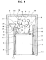
- Fig. 1 shows an arranged on an elevator car 1 assembly tool 2.
- the elevator car 1 is by means of a hoist 3 along in a hoistway 4th arranged guide rails 5 can be raised and lowered.
- the elevator car 1 is guided by guide shoes 1.1 to the guide rails 5.
- the hoist 3 is suspended on a load hook 6 a shaft ceiling 7, wherein a support means 8, for example, a chain or straps with a clevis 9 of a cab yoke 10 is connected.
- the assembly tool 2 consists of a pivot support 11 which is pivotally mounted on an axis 12 of a tool foot 13.
- the tool foot 13 is supported by the cab yoke 10.
- a lift carrier 14 carrying load carrier 15 is provided at the free end of the pivot support 11 .
- standing installation personnel 16 operates the hoist 3 and the mounting tool 2, wherein a first stop 17 and a second stop 18 limits the pivoting movement of the mounting tool 3.
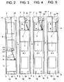
- Fig. 2 to Fig. 5 show the assembly of the elevator drive 14 by means of the elevator car 1 and the assembly tool 2 and the hoist 3.
- the elevator car 1 is located on buffers 19 of a shaft pit 20.
- the elevator car 1 can also be held in the elevator shaft 4 by means of a catching device or by means of clamps or bolts acting on the guide rails 5 or by means of supports supported in the shaft pit 20.
- the pivot support 11 of the assembly tool 2 extends to the next higher floor 4.1, from which the elevator drive 14 is transferred by means of the hoist 3 on the load carrier 15 of the pivot support 11.
- the transfer process is symbolized by arrow P1.
- the elevator drive 14 is festgegurtet on the load carrier 15 and the support means 8 of the hoist 3 attached to the clevis 9 of the cabin yoke 10.
- Fig. 3 is the Elevator car 1 has been lifted by hoist 3 so far that the load carrier 15 is pivotable via a motor console designated 21.
- Fig. 4 the elevator drive 14 is transferred from the load carrier 15 to the motor console 21.
- the transfer process is symbolized by arrow P2.
- the elevator car 1 is lowered until the elevator drive 14 rests on the motor console 21. Thereafter, the elevator drive 14 is bolted firmly to the engine bracket 21.
- the assembly tool 2, together with the hoist 3 allows a mounting of the elevator drive 14 scarce (a few centimeters) below the shaft ceiling. 7
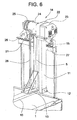
- Fig. 6 shows details of the elevator drive 14 and the assembly tool 2.
- the elevator drive 14 consists of a motor 22 with motor plate 23, a traction sheave with housing 24 and arranged on the traction sheave housing 24 brake unit 25.
- a housing foot 26 of the traction sheave housing 24 is supported by the motor bracket 21, the is supported on a arranged on the guide rails 5 console support 27.
- the engine plate 23 is supported on the bracket 27.
- an opening in the traction sheave housing 24 is provided, through which a flat belt 28 serving as a support and propellant is guided over the traction sheave.
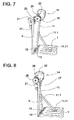
- FIGS. 7 and 8 show a variant of the assembly tool 2.
- the pivot support 11 instead of the stops 17,18 a support leg 11.1, which is as in Fig. 7 shown supported on the cabin roof.
- the support leg 11.11 loads the cabin roof no more than a standing on the cab roof fitter.
- the Swivel support 11 pivoted about the engine console 21, wherein the support leg 11.11 is raised.
- the elevator car 1 is suspended at the corners on suspension means, wherein the support means are merged below the load carrier 15 on the diagonal intersection of the cabin roof and are connected to the support means 8 of the hoist 3.
Landscapes
- Cage And Drive Apparatuses For Elevators (AREA)
- Lift-Guide Devices, And Elevator Ropes And Cables (AREA)
Description
Die Erfindung betrifft eine Einrichtung zur Montage eines Aufzugsantriebes, der mittels Montagewerkzeug und Hebezeug knapp unterhalb einer Schachtdecke montierbar ist.The invention relates to a device for mounting an elevator drive, which can be mounted by means of assembly tool and hoist just below a shaft ceiling.
Aus der Schrift
Ein Nachteil der bekannten Einrichtung liegt darin, dass der Ausleger im Schachtquerschnitt viel Platz beansprucht. Dadurch wird der Transfer des Aufzugsantriebes vom Ausleger auf die Motorkonsole erschwert.A disadvantage of the known device is that the boom takes up a lot of space in the shaft cross-section. As a result, the transfer of the elevator drive from the boom to the engine console is made more difficult.
Hier will die Erfindung Abhilfe schaffen. Die Erfindung, wie sie in Anspruch 1 gekennzeichnet ist, löst die Aufgabe, die Nachteile der bekannten Einrichtung zu vermeiden und eine Montageeinrichtung zu schaffen, mittels der ein Aufzugsantrieb unter der Schachtdecke einfach montierbar ist.The invention aims to remedy this situation. The invention, as characterized in
Vorteilhafte Weiterbildungen der Erfindung sind in den abhängigen Patentansprüchen angegeben.Advantageous developments of the invention are specified in the dependent claims.
Die durch die Erfindung erreichten Vorteile sind im wesentlichen darin zu sehen, dass zur Montage der Aufzugsantrieb mittels einfachem Montagewerkzeug bis unter die Schachtdecke hochhebbar und anschliessend an der Motorkonsole anbringbar ist. Das Montagewerkzeug ist einfach und billig herstellbar. Mit dem Montagewerkzeug ist ein sicherer und schneller Montagevorgang machbar. Zudem kann der bestehende Lasthaken an der Schachtkopfdecke verwendet werden. Da der Aufzugsantrieb während der Montage stets an mindestens einer Konsole (Montagewerkzeug bzw. Motorkonsole) festgemacht ist, ist die Sicherheit für das Montagepersonal gewährleistet.The advantages achieved by the invention are in essential to see that for mounting the elevator drive by means of a simple assembly tool can be lifted up below the shaft ceiling and then attachable to the motor console. The assembly tool is simple and inexpensive to produce. With the assembly tool a safe and quick installation process is feasible. In addition, the existing load hook on the manhole cover can be used. Since the elevator drive is always fastened to at least one console (assembly tool or motor console) during installation, the safety for the installation personnel is guaranteed.
Anhand der beiliegenden Figuren wird die vorliegende Erfindung näher erläutert.Reference to the accompanying figures, the present invention will be explained in more detail.
Es zeigen:
-
Fig. 1
ein an einer Aufzugskabine angeordnetes Montagewerkzeug, -
Fig. 2 bis Fig. 5
die Montage eines Aufzugsantriebes mittels des Montagewerkzeuges, -
Fig. 6
Einzelheiten des Aufzugsantriebes und des Montagewerkzeuges, -
Fig. 7 und Fig. 8
eine Ausführungsvariante des Montagewerkzeuges.
-
Fig. 1
a mounted on an elevator car assembly tool, -
Fig. 2 to Fig. 5
the installation of an elevator drive by means of the assembly tool, -
Fig. 6
Details of the elevator drive and the assembly tool, -
FIGS. 7 and 8
a variant of the assembly tool.
Das Montagewerkzeug 2 besteht aus einer Schwenkstütze 11, die schwenkbar an einer Achse 12 eines Werkzeugfusses 13 angeordnet ist. Der Werkzeugfuss 13 wird vom Kabinenjoch 10 getragen. Am freien Ende der Schwenkstütze 11 ist ein einen Aufzugsantrieb 14 tragender Lastträger 15 vorgesehen. Auf dem Kabinenjoch 10 stehendes Montagepersonal 16 bedient das Hebezeug 3 und das Montagewerkzeug 2, wobei ein erster Anschlag 17 und ein zweiter Anschlag 18 die Schwenkbewegung des Montagewerkzeuges 3 begrenzt.The
Die Aufzugskabine 1 ist an den Ecken an Tragmitteln aufgehängt, wobei die Tragmittel unterhalb des Lastträgers 15 über dem Diagonalenschnittpunkt des Kabinendaches zusammengeführt sind und mit dem Tragmittel 8 des Hebezeuges 3 verbunden sind.The
Claims (4)
- Equipment for mounting a lift drive (14), which can be mounted by means of a mounting tool (2) and hoist (3) closely below a shaft ceiling (7), characterised in that the mounting tool (2) supporting the lift drive (14) is arranged at a lift cage (1) movable in a lift shaft (4) and the lift cage (1) is raisable and lowerable by means of a hoist (3).
- Equipment according to claim 1, characterised in that the mounting tool (2) comprises a tool foot (13), which is arranged at the cage yoke (10) of the lift cage (1), with an axle (12), wherein a pivot support (11) comprising a load carrier (15) for receiving the lift drive (14) is pivotably arranged at the axle (12).
- Method of mounting a lift drive (14) with use of equipment for mounting the lift drive (14) according to claim 1 or 2, wherein the lift drive (14) can be mounted by means of a mounting tool (2) and a hoist (3) closely below a shaft ceiling (7), characterised in that in a first step a lift cage (1) is held in a lift shaft (4), wherein the mounting tool (2) arranged at the lift cage (1) reaches to the next higher storey, from which the lift drive (14) is transferrable by means of the hoist (3) to the mounting tool (2), that in a further step the lift cage (1) is raised by means of the hoist (3) until the lift drive (14) is pivotable over a motor bracket (21) and transferrable and that in a further step after the transfer process the lift cage (1) is lowered by means of the hoist (3) until the lift drive (14) rests on the motor bracket (21).
- Method according to claim 3, characterised in that the lift cage (1) is held on buffers (19) of a shaft pit (20) of the lift shaft (4).
Priority Applications (1)
| Application Number | Priority Date | Filing Date | Title |
|---|---|---|---|
| EP20050103705 EP1593641B1 (en) | 2004-05-07 | 2005-05-03 | Apparatus for the installation of an elevator hoisting machine |
Applications Claiming Priority (3)
| Application Number | Priority Date | Filing Date | Title |
|---|---|---|---|
| EP04405289 | 2004-05-07 | ||
| EP04405289 | 2004-05-07 | ||
| EP20050103705 EP1593641B1 (en) | 2004-05-07 | 2005-05-03 | Apparatus for the installation of an elevator hoisting machine |
Publications (2)
| Publication Number | Publication Date |
|---|---|
| EP1593641A1 EP1593641A1 (en) | 2005-11-09 |
| EP1593641B1 true EP1593641B1 (en) | 2014-12-10 |
Family
ID=35445887
Family Applications (1)
| Application Number | Title | Priority Date | Filing Date |
|---|---|---|---|
| EP20050103705 Expired - Lifetime EP1593641B1 (en) | 2004-05-07 | 2005-05-03 | Apparatus for the installation of an elevator hoisting machine |
Country Status (1)
| Country | Link |
|---|---|
| EP (1) | EP1593641B1 (en) |
Cited By (2)
| Publication number | Priority date | Publication date | Assignee | Title |
|---|---|---|---|---|
| US11198595B2 (en) | 2019-03-07 | 2021-12-14 | Tk Elevator Innovation And Operations Gmbh | Methods and apparatuses for installing elevator machines |
| DE102023122504A1 (en) * | 2023-08-22 | 2025-02-27 | Tk Elevator Innovation And Operations Gmbh | Method for installing a drive unit of an elevator system arrangement and corresponding elevator system arrangement and use |
Families Citing this family (4)
| Publication number | Priority date | Publication date | Assignee | Title |
|---|---|---|---|---|
| CN101139062A (en) | 2006-09-06 | 2008-03-12 | 因温特奥股份公司 | Guide device for an elevator, elevator with such a guide device, and method for operating such an elevator |
| WO2009044481A1 (en) † | 2007-10-05 | 2009-04-09 | Mitsubishi Electric Corporation | Lifting device for elevator, elevator car frame, and lifting method for elevator |
| WO2010065040A1 (en) * | 2008-12-05 | 2010-06-10 | Otis Elevator Company | Elevator system and installation method |
| EP3838828B1 (en) * | 2019-12-19 | 2023-02-08 | KONE Corporation | Elevator arrangement and method |
Family Cites Families (4)
| Publication number | Priority date | Publication date | Assignee | Title |
|---|---|---|---|---|
| US6357556B1 (en) * | 1997-03-07 | 2002-03-19 | Kone Corporation | Procedure and apparatus for the installation of an elevator |
| JP2000034072A (en) * | 1998-07-17 | 2000-02-02 | Hitachi Building Systems Co Ltd | Elevator hoist installation equipment |
| JP2000226169A (en) * | 1999-02-08 | 2000-08-15 | Hitachi Building Systems Co Ltd | Elevator installation method |
| JP2003292263A (en) * | 2002-04-05 | 2003-10-15 | Fujitec Co Ltd | Elevator apparatus lifting device and method |
-
2005
- 2005-05-03 EP EP20050103705 patent/EP1593641B1/en not_active Expired - Lifetime
Cited By (2)
| Publication number | Priority date | Publication date | Assignee | Title |
|---|---|---|---|---|
| US11198595B2 (en) | 2019-03-07 | 2021-12-14 | Tk Elevator Innovation And Operations Gmbh | Methods and apparatuses for installing elevator machines |
| DE102023122504A1 (en) * | 2023-08-22 | 2025-02-27 | Tk Elevator Innovation And Operations Gmbh | Method for installing a drive unit of an elevator system arrangement and corresponding elevator system arrangement and use |
Also Published As
| Publication number | Publication date |
|---|---|
| EP1593641A1 (en) | 2005-11-09 |
Similar Documents
| Publication | Publication Date | Title |
|---|---|---|
| EP2935075B1 (en) | Installation method for a lift | |
| DE69805257T2 (en) | METHOD AND APPARATUS FOR INSTALLING AN ELEVATOR | |
| EP3548413A1 (en) | Lift system and method for constructing such an elevator system | |
| CN1962387B (en) | Method for establishing an elevator equipment and elevator equipment therefor | |
| DE112014006899T5 (en) | Aufzughubmaschinen attachment device | |
| EP2423147B1 (en) | Assembly for rotating a load | |
| EP1593641B1 (en) | Apparatus for the installation of an elevator hoisting machine | |
| EP2014603B1 (en) | Vehicle crane | |
| CN112566864B (en) | Application method of lift extension technology of elevator | |
| EP1780167A2 (en) | Mobile crane with counterweight | |
| US2674378A (en) | Removable counter weight for truck cranes | |
| WO2011082897A1 (en) | Double-decker lift installation | |
| CN211283463U (en) | Sliding adjustment lifting device | |
| JP6969686B2 (en) | How to extend the lift of a construction elevator | |
| WO2014095352A1 (en) | Maintenance method for a lift | |
| EP1245522B1 (en) | Procedure for mounting a drive unit in an elevator shaft | |
| DE102008046867B4 (en) | Electric chain hoist with load arm | |
| CN219823333U (en) | Lifting mechanism of well construction lifter | |
| DE2410807C2 (en) | Crane trolley with a heavy load handling device and a combined device to prevent slack rope and to prevent falling below a specified minimum hoisting rope force | |
| EP1314678B1 (en) | Safety device for maintenance personnel | |
| CN214733983U (en) | A simple lifting device passing through the beam body | |
| JP2007210703A (en) | Device and method for installing hoist machine in machine-room-less elevator | |
| US11059701B2 (en) | Methods and apparatuses for lifting elevator cars during installation | |
| DE102020121344B4 (en) | Mobile crane with trailer | |
| DE3306672C1 (en) | Lifting device to relieve the hoisting ropes in mining shafts |
Legal Events
| Date | Code | Title | Description |
|---|---|---|---|
| PUAI | Public reference made under article 153(3) epc to a published international application that has entered the european phase |
Free format text: ORIGINAL CODE: 0009012 |
|
| AK | Designated contracting states |
Kind code of ref document: A1 Designated state(s): AT BE BG CH CY CZ DE DK EE ES FI FR GB GR HU IE IS IT LI LT LU MC NL PL PT RO SE SI SK TR |
|
| AX | Request for extension of the european patent |
Extension state: AL BA HR LV MK YU |
|
| 17P | Request for examination filed |
Effective date: 20060418 |
|
| AKX | Designation fees paid |
Designated state(s): AT CH DE FR GB LI |
|
| GRAP | Despatch of communication of intention to grant a patent |
Free format text: ORIGINAL CODE: EPIDOSNIGR1 |
|
| INTG | Intention to grant announced |
Effective date: 20131010 |
|
| GRAP | Despatch of communication of intention to grant a patent |
Free format text: ORIGINAL CODE: EPIDOSNIGR1 |
|
| INTG | Intention to grant announced |
Effective date: 20140626 |
|
| GRAP | Despatch of communication of intention to grant a patent |
Free format text: ORIGINAL CODE: EPIDOSNIGR1 |
|
| INTG | Intention to grant announced |
Effective date: 20140909 |
|
| GRAS | Grant fee paid |
Free format text: ORIGINAL CODE: EPIDOSNIGR3 |
|
| GRAA | (expected) grant |
Free format text: ORIGINAL CODE: 0009210 |
|
| AK | Designated contracting states |
Kind code of ref document: B1 Designated state(s): AT CH DE FR GB LI |
|
| REG | Reference to a national code |
Ref country code: GB Ref legal event code: FG4D Free format text: NOT ENGLISH |
|
| REG | Reference to a national code |
Ref country code: CH Ref legal event code: EP |
|
| REG | Reference to a national code |
Ref country code: DE Ref legal event code: R096 Ref document number: 502005014616 Country of ref document: DE Effective date: 20150115 Ref country code: AT Ref legal event code: REF Ref document number: 700543 Country of ref document: AT Kind code of ref document: T Effective date: 20150115 |
|
| REG | Reference to a national code |
Ref country code: DE Ref legal event code: R097 Ref document number: 502005014616 Country of ref document: DE |
|
| PLBE | No opposition filed within time limit |
Free format text: ORIGINAL CODE: 0009261 |
|
| STAA | Information on the status of an ep patent application or granted ep patent |
Free format text: STATUS: NO OPPOSITION FILED WITHIN TIME LIMIT |
|
| 26N | No opposition filed |
Effective date: 20150911 |
|
| REG | Reference to a national code |
Ref country code: FR Ref legal event code: PLFP Year of fee payment: 12 |
|
| REG | Reference to a national code |
Ref country code: FR Ref legal event code: PLFP Year of fee payment: 13 |
|
| REG | Reference to a national code |
Ref country code: FR Ref legal event code: PLFP Year of fee payment: 14 |
|
| REG | Reference to a national code |
Ref country code: DE Ref legal event code: R084 Ref document number: 502005014616 Country of ref document: DE |
|
| PGFP | Annual fee paid to national office [announced via postgrant information from national office to epo] |
Ref country code: GB Payment date: 20220524 Year of fee payment: 18 |
|
| REG | Reference to a national code |
Ref country code: DE Ref legal event code: R084 Ref document number: 502005014616 Country of ref document: DE |
|
| PGFP | Annual fee paid to national office [announced via postgrant information from national office to epo] |
Ref country code: AT Payment date: 20220518 Year of fee payment: 18 |
|
| REG | Reference to a national code |
Ref country code: AT Ref legal event code: MM01 Ref document number: 700543 Country of ref document: AT Kind code of ref document: T Effective date: 20230503 |
|
| GBPC | Gb: european patent ceased through non-payment of renewal fee |
Effective date: 20230503 |
|
| PG25 | Lapsed in a contracting state [announced via postgrant information from national office to epo] |
Ref country code: AT Free format text: LAPSE BECAUSE OF NON-PAYMENT OF DUE FEES Effective date: 20230503 |
|
| PG25 | Lapsed in a contracting state [announced via postgrant information from national office to epo] |
Ref country code: GB Free format text: LAPSE BECAUSE OF NON-PAYMENT OF DUE FEES Effective date: 20230503 |
|
| PGFP | Annual fee paid to national office [announced via postgrant information from national office to epo] |
Ref country code: DE Payment date: 20240529 Year of fee payment: 20 |
|
| PGFP | Annual fee paid to national office [announced via postgrant information from national office to epo] |
Ref country code: CH Payment date: 20240602 Year of fee payment: 20 |
|
| PGFP | Annual fee paid to national office [announced via postgrant information from national office to epo] |
Ref country code: FR Payment date: 20240527 Year of fee payment: 20 |
|
| REG | Reference to a national code |
Ref country code: DE Ref legal event code: R071 Ref document number: 502005014616 Country of ref document: DE |
|
| REG | Reference to a national code |
Ref country code: CH Ref legal event code: PL |