EP1593540A2 - Kupplingseinrichtung einer Getriebeanordnung eines Fahrzeuges, vorzugsweise eines Kraftfahrzeuges - Google Patents
Kupplingseinrichtung einer Getriebeanordnung eines Fahrzeuges, vorzugsweise eines Kraftfahrzeuges Download PDFInfo
- Publication number
- EP1593540A2 EP1593540A2 EP05008117A EP05008117A EP1593540A2 EP 1593540 A2 EP1593540 A2 EP 1593540A2 EP 05008117 A EP05008117 A EP 05008117A EP 05008117 A EP05008117 A EP 05008117A EP 1593540 A2 EP1593540 A2 EP 1593540A2
- Authority
- EP
- European Patent Office
- Prior art keywords
- clutches
- coupling
- advantageously
- carrier
- cam
- Prior art date
- Legal status (The legal status is an assumption and is not a legal conclusion. Google has not performed a legal analysis and makes no representation as to the accuracy of the status listed.)
- Withdrawn
Links
- 230000005540 biological transmission Effects 0.000 title description 6
- 230000008878 coupling Effects 0.000 claims description 31
- 238000010168 coupling process Methods 0.000 claims description 31
- 238000005859 coupling reaction Methods 0.000 claims description 31
- 241000446313 Lamella Species 0.000 claims description 5
- 230000004323 axial length Effects 0.000 claims description 5
- 238000009434 installation Methods 0.000 description 4
- 230000007423 decrease Effects 0.000 description 3
- 238000010276 construction Methods 0.000 description 1
- 230000007935 neutral effect Effects 0.000 description 1
- 230000002093 peripheral effect Effects 0.000 description 1
Images


Classifications
-
- F—MECHANICAL ENGINEERING; LIGHTING; HEATING; WEAPONS; BLASTING
- F16—ENGINEERING ELEMENTS AND UNITS; GENERAL MEASURES FOR PRODUCING AND MAINTAINING EFFECTIVE FUNCTIONING OF MACHINES OR INSTALLATIONS; THERMAL INSULATION IN GENERAL
- F16D—COUPLINGS FOR TRANSMITTING ROTATION; CLUTCHES; BRAKES
- F16D21/00—Systems comprising a plurality of actuated clutches
- F16D21/02—Systems comprising a plurality of actuated clutches for interconnecting three or more shafts or other transmission members in different ways
- F16D21/06—Systems comprising a plurality of actuated clutches for interconnecting three or more shafts or other transmission members in different ways at least two driving shafts or two driven shafts being concentric
-
- B—PERFORMING OPERATIONS; TRANSPORTING
- B60—VEHICLES IN GENERAL
- B60K—ARRANGEMENT OR MOUNTING OF PROPULSION UNITS OR OF TRANSMISSIONS IN VEHICLES; ARRANGEMENT OR MOUNTING OF PLURAL DIVERSE PRIME-MOVERS IN VEHICLES; AUXILIARY DRIVES FOR VEHICLES; INSTRUMENTATION OR DASHBOARDS FOR VEHICLES; ARRANGEMENTS IN CONNECTION WITH COOLING, AIR INTAKE, GAS EXHAUST OR FUEL SUPPLY OF PROPULSION UNITS IN VEHICLES
- B60K17/00—Arrangement or mounting of transmissions in vehicles
- B60K17/34—Arrangement or mounting of transmissions in vehicles for driving both front and rear wheels, e.g. four wheel drive vehicles
- B60K17/344—Arrangement or mounting of transmissions in vehicles for driving both front and rear wheels, e.g. four wheel drive vehicles having a transfer gear
- B60K17/346—Arrangement or mounting of transmissions in vehicles for driving both front and rear wheels, e.g. four wheel drive vehicles having a transfer gear the transfer gear being a differential gear
- B60K17/3462—Arrangement or mounting of transmissions in vehicles for driving both front and rear wheels, e.g. four wheel drive vehicles having a transfer gear the transfer gear being a differential gear with means for changing distribution of torque between front and rear wheels
-
- B—PERFORMING OPERATIONS; TRANSPORTING
- B60—VEHICLES IN GENERAL
- B60K—ARRANGEMENT OR MOUNTING OF PROPULSION UNITS OR OF TRANSMISSIONS IN VEHICLES; ARRANGEMENT OR MOUNTING OF PLURAL DIVERSE PRIME-MOVERS IN VEHICLES; AUXILIARY DRIVES FOR VEHICLES; INSTRUMENTATION OR DASHBOARDS FOR VEHICLES; ARRANGEMENTS IN CONNECTION WITH COOLING, AIR INTAKE, GAS EXHAUST OR FUEL SUPPLY OF PROPULSION UNITS IN VEHICLES
- B60K23/00—Arrangement or mounting of control devices for vehicle transmissions, or parts thereof, not otherwise provided for
- B60K23/04—Arrangement or mounting of control devices for vehicle transmissions, or parts thereof, not otherwise provided for for differential gearing
-
- B—PERFORMING OPERATIONS; TRANSPORTING
- B60—VEHICLES IN GENERAL
- B60K—ARRANGEMENT OR MOUNTING OF PROPULSION UNITS OR OF TRANSMISSIONS IN VEHICLES; ARRANGEMENT OR MOUNTING OF PLURAL DIVERSE PRIME-MOVERS IN VEHICLES; AUXILIARY DRIVES FOR VEHICLES; INSTRUMENTATION OR DASHBOARDS FOR VEHICLES; ARRANGEMENTS IN CONNECTION WITH COOLING, AIR INTAKE, GAS EXHAUST OR FUEL SUPPLY OF PROPULSION UNITS IN VEHICLES
- B60K23/00—Arrangement or mounting of control devices for vehicle transmissions, or parts thereof, not otherwise provided for
- B60K23/08—Arrangement or mounting of control devices for vehicle transmissions, or parts thereof, not otherwise provided for for changing number of driven wheels, for switching from driving one axle to driving two or more axles
- B60K23/0808—Arrangement or mounting of control devices for vehicle transmissions, or parts thereof, not otherwise provided for for changing number of driven wheels, for switching from driving one axle to driving two or more axles for varying torque distribution between driven axles, e.g. by transfer clutch
-
- F—MECHANICAL ENGINEERING; LIGHTING; HEATING; WEAPONS; BLASTING
- F16—ENGINEERING ELEMENTS AND UNITS; GENERAL MEASURES FOR PRODUCING AND MAINTAINING EFFECTIVE FUNCTIONING OF MACHINES OR INSTALLATIONS; THERMAL INSULATION IN GENERAL
- F16D—COUPLINGS FOR TRANSMITTING ROTATION; CLUTCHES; BRAKES
- F16D28/00—Electrically-actuated clutches
-
- F—MECHANICAL ENGINEERING; LIGHTING; HEATING; WEAPONS; BLASTING
- F16—ENGINEERING ELEMENTS AND UNITS; GENERAL MEASURES FOR PRODUCING AND MAINTAINING EFFECTIVE FUNCTIONING OF MACHINES OR INSTALLATIONS; THERMAL INSULATION IN GENERAL
- F16D—COUPLINGS FOR TRANSMITTING ROTATION; CLUTCHES; BRAKES
- F16D21/00—Systems comprising a plurality of actuated clutches
- F16D21/02—Systems comprising a plurality of actuated clutches for interconnecting three or more shafts or other transmission members in different ways
- F16D21/06—Systems comprising a plurality of actuated clutches for interconnecting three or more shafts or other transmission members in different ways at least two driving shafts or two driven shafts being concentric
- F16D2021/0638—Electrically actuated multiple lamellae clutches
-
- F—MECHANICAL ENGINEERING; LIGHTING; HEATING; WEAPONS; BLASTING
- F16—ENGINEERING ELEMENTS AND UNITS; GENERAL MEASURES FOR PRODUCING AND MAINTAINING EFFECTIVE FUNCTIONING OF MACHINES OR INSTALLATIONS; THERMAL INSULATION IN GENERAL
- F16D—COUPLINGS FOR TRANSMITTING ROTATION; CLUTCHES; BRAKES
- F16D27/00—Magnetically- or electrically- actuated clutches; Control or electric circuits therefor
- F16D27/004—Magnetically- or electrically- actuated clutches; Control or electric circuits therefor with permanent magnets combined with electromagnets
-
- F—MECHANICAL ENGINEERING; LIGHTING; HEATING; WEAPONS; BLASTING
- F16—ENGINEERING ELEMENTS AND UNITS; GENERAL MEASURES FOR PRODUCING AND MAINTAINING EFFECTIVE FUNCTIONING OF MACHINES OR INSTALLATIONS; THERMAL INSULATION IN GENERAL
- F16H—GEARING
- F16H25/00—Gearings comprising primarily only cams, cam-followers and screw-and-nut mechanisms
- F16H25/18—Gearings comprising primarily only cams, cam-followers and screw-and-nut mechanisms for conveying or interconverting oscillating or reciprocating motions
- F16H25/186—Gearings comprising primarily only cams, cam-followers and screw-and-nut mechanisms for conveying or interconverting oscillating or reciprocating motions with reciprocation along the axis of oscillation
Definitions
- the invention relates to a coupling device of a transmission arrangement a vehicle, preferably a motor vehicle, according to the preamble of claim 1.
- the invention is based on the object, the generic coupling device in such a way that the gear arrangement has little installation space needed.
- the two clutches at least partially intertwined.
- Advantageous are the two Fully assembled couplings, so that the axial length of the Coupling device essentially only by the axial length of a coupling is determined.
- the coupling device and the transmission only a small axial installation length, so that this transmission can be used excellently in tight installation conditions.
- the coupling device described below is part of a Differential drive used in four-wheel drives of motor vehicles and optimally distributes the torque to the respective wheels becomes. Such differential drives are known and therefore are not explained in detail.
- the coupling device With the coupling device, the torque split on two side shafts of the four-wheel drive via a planetary gear become.
- the coupling device has a cam 1, the rotationally fixed sits on an inner disk carrier 2. He is designed as a hollow carrier.
- the cam 1 is provided on the circumference with a toothing 3, in the a pinion 4 of an electric motor 5 engages.
- the cam 1 is supported via a bearing 6 on the bottom 7 of a housing 8 from. It's about a part its circumference provided with a jacket 9, which the cam 1 with partially surrounds radial distance.
- the housing jacket 9 approximately over 180 ° (FIG. 2).
- the Electric motor 5 attached on the housing 8 is the Electric motor 5 attached.
- the pinion 4 protrudes through a peripheral depression 10 (Fig. 2) of the bottom 7 of the housing 8.
- the teeth 3 of the cam 1 is provided on a projection 11 (Fig. 2), which only extends over part of the circumference of the cam 1.
- the lead 11 is in the circumferential direction of the cam 1 so long that the coupling device be reliably operated in a manner to be described can.
- the projection 11 extends over an angular range of about 60 °.
- the projection 11 is above the Housing 8 radially over.
- the housing jacket 8 is provided so that it Rotation of the cam 1 when actuated by means of the electric motor. 5 not disabled.
- the projection 11 can therefore be in the area between the ends of the housing shell 9 rotate freely.
- the cam 1 is on its side facing away from the electric motor 5 side two concentric annular grooves 12 and 13 provided, the distance from each other have and have approximately semicircular cross-section.
- the ring grooves 12, 13 engage balls 14, 15 which extend beyond the circumference of the respective ones Ring grooves 12, 13 are arranged distributed.
- the cam 1 are an annular ball ramp 16 and a disk-shaped Ball ramp 17 opposite.
- the two ball ramps 16, 17 are located in a common plane (Fig. 1).
- the annular ball ramp 16 lies on the circumference of the disc-shaped ball ramp 17, which in turn on the inner disk carrier 2 is mounted.
- the two ball ramps 16, 17 can be moved axially against each other slightly to a radial outer fin block 18 or a radially inner fin block 19 too actuate.
- the two ball ramps 16, 17 are, as shown in FIG. 3, with over its circumference distributed arranged recesses 20, 21 provided. They each extend in the circumferential direction of the ball ramps 16, 17.
- the recesses 20 of the outer ball ramp 16 are longer than the recesses 21 of the radially inner Ball ramp 17.
- the wells 20 are each formed the same and have a about half the length extending freewheel area 22, in which the grooves 20 have constant depth. At this freewheel area 22, which has constant width over its length, closes an adjustment range 23, which tapers towards its free end and in which the depth the recess 20 decreases steadily towards the free end.
- the recesses 21 of the radially inner ball ramp 17 also have a Freewheel area 24, in which the recesses 21 constant width and depth to have.
- To the freewheel area 24 includes an adjustment 25, which is tapered towards its free end and its width and depth in Direction towards the free end steadily decreases.
- the depressions 21, the same are formed, are twisted by 180 ° compared to the wells 20 arranged.
- each of the recesses 20, 21 each engage a ball 14 and 15, respectively.
- the cam 1 means of the pinion 4 in the desired direction so rotated that the balls 14th or 15 from the respective freewheel area 22, 24 into the adjustment area 23, 25 of the ball ramps 16, 17 arrive.
- the radially outer or the radially inner ball ramp 16, 17 axially displaced, whereby about plungers 26, 27 of the respective slat block 18 and 19 compressed becomes. This will be described in detail later.
- the pressure pieces 26, 27 protrude through openings 31, 32, which on a plate carrier 33 are provided. He has a cylindrical shell 34, whose Axis coincides with the axis of the inner disk carrier 2.
- the coat 34 surrounds the inner fin block 19, which on the inner wall of the shell 34 abuts and is mounted on the inner disk carrier 2.
- the jacket 34 is surrounded by the outer fin block 18, which on the outside of the Carrier 34 is present.
- the two lamella blocks 18, 19 consist of annular, superimposed annular lamellae.
- the two equally long lamellar blocks 18, 19 are at the common Plate carrier 33 held.
- the outer fin block 18 is located on a Bottom 39 of an outer disk carrier 40, the left output of the Differential gear forms.
- the radially lying bottom 39 goes into an in Direction of the cam 1 extending cylinder shell 41st over which surrounds the outer fin block 18 with low radial clearance and surrounded by the cylinder jacket 37 of the housing 38 with low radial clearance is.
- the cylinder jacket 37 projects beyond the cylinder jacket 41, the distance from the radial flange 36 has.
- On the outer fin block 18 is located a pressure plate 42, the same radial width as the lamella block 18 has.
- the plungers 26 exercise via an intermediate disc 43 a Force on the pressure plate 42 on.
- a pressure plate 44 On the inner fin block 19 is a pressure plate 44, on the the pressure pieces 27 act via an intermediate disc 45.
- the two pressure washers 42, 44 are at the same height in a radial plane.
- the outer pressure plate 42 has at the outer edge a thin annular wall 46, with which it surrounds the outer washer 43.
- the pressure plate 42 abuts against the inner wall of the cylinder jacket 41 and is therefore flawless radially centered. From the jacket 34 of the plate carrier 33 has the outer Pressure disk 42 small radial distance.
- the inner pressure washer 44 has a thin annular wall at the radially inner edge 47, which rests against the inner disk carrier 2 and the inner washer 45 at the inner edge encloses.
- the bottom 39 of the outer disk carrier 40 has a thickened portion, on which the outer fin block 18 rests. This thickened area of the Bodens 39 goes into a thinner, radially inner floor area over, on which the cylinder jacket 34 of the disk carrier 33 with his Front side rests.
- the inner disk carrier 2 has a radial annular flange 48, which is advantageously integrally formed with the inner disk carrier 2 and surrounded by the jacket 34 of the disk carrier 33.
- the ring flange 48 extends to the inner wall of the shell 34 and is located above a bearing 49 at the thinner portion of the bottom 39 of the outer disk carrier 40 at.
- the radially extending bottom 39 connects the cylinder jacket 41 with a Sleeve 50, with the outer disk carrier 40 on the inner disk carrier. 2 rests.
- the sleeve 50 is advantageously formed integrally with the bottom 39.
- a sleeve 51 of the housing 38 On the sleeve 50 of the outer disk carrier 40 is a sleeve 51 of the housing 38 on.
- the sleeve 51 is through a radial bottom 52 with the cylinder jacket 37 of the housing 38 connected.
- the outer disk carrier 40 is with its bottom 39 with an intermediate layer a bearing 53 rotatably supported on the bottom 52 of the housing 38. Of the Diameter of the bearing 53 is greater than the diameter of the bearing 49th The bearing 53 surrounds the casing 34 of the disk carrier 33, in the axial direction seen, by far. The bearing 49 is located, viewed in the axial direction, within the jacket 34 of the disc carrier 33.
- the bottom 52 of the housing 38 is supported via a bearing 54 on a support disk 55, which is arranged on the sleeve 51 of the housing 38.
- the lamella blocks 18, 19 protected housed in the housing 38.
- the common plate carrier 33 is provided so that a constructive simple construction results. Since the two lamellar blocks 18, 19 coaxial lie to each other and are juxtaposed, the coupling device is characterized by only a small axial length. She can do it be used in cramped installation conditions in the vehicle.
- the lamellar blocks 18, 19 can be actuated independently of each other, to the drive torque to the respective wheels to the desired extent to distribute.
- Fig. 4b shows the neutral position of the coupling device. She is characterized in that the balls 14, 15 between the cam 1 and the two ball ramps 16, 17 in the freewheel area 22, 24th the recesses 20, 21 of the ball ramps are located. The torque is distributed equally on both side shafts of the differential gear.
- Fig. 5 the left side shaft 57 is shown. The side shaft 57 is over a bevel gear 58 in engagement with a differential case or differential carrier 59.
- the two lamellae blocks 18, 19, which the couplings form, are out of action. This will drive torque to both Distributed side shafts of the differential gear in half.
- the differential case 59 is part of a planetary gear 60.
- the differential case 59 forms the planet carrier that drives the left side shaft 57.
- the sun gear 61 the planetary gear 60 is rotatably connected to the inner disk carrier 2 and forms the right side wave.
- the planet carrier or the differential housing 59 drives a countershaft 62, which is parallel to the hollow shaft 2, which is formed by the inner disk carrier 2.
- the pinion 4 of the Servomotor 5 is rotated in one direction, so that the cam 1 in the Required direction limited rotated about its axis.
- the ball ramp 16 exercises on the plungers 26 and the pressure plate 42 an axial force on the plate block 18 from.
- These Force F is indicated in Fig. 4c by a corresponding arrow.
- the wells 20 and 21 of the two Ball ramps 16, 17 rotated by 180 ° to each other, wherein the outer recesses 20 of the ball ramp 16 in the circumferential direction substantially are longer than the recesses 21 of the inner ball ramp 17.
- the in Circumferentially measured length of the freewheeling area 22 of the wells 20 corresponds approximately to the total length of the recesses 21 of the inner Ball ramp 17.
- the balls 14, 15 are arranged in the recesses 20, 21, that the outer balls 40 still in the freewheel region 22 of the wells 20 are when the radially inner balls 15 in the adjustment 25 of the wells 21 are located.
- the drive is via the bevel gear 58 on the formed as a ring gear Differential case 59. He is about the translation stage with the common plate carrier 33 for the outer and the inner plate block 18, 19 connected and turns faster. By closing the lamella blocks 18 and 19 in the manner described the respective outside of the curve Rad (outside of the bend output) imprinted an additional torque.
Landscapes
- Engineering & Computer Science (AREA)
- Mechanical Engineering (AREA)
- General Engineering & Computer Science (AREA)
- Chemical & Material Sciences (AREA)
- Combustion & Propulsion (AREA)
- Transportation (AREA)
- Physics & Mathematics (AREA)
- Electromagnetism (AREA)
- Retarders (AREA)
- Arrangement And Driving Of Transmission Devices (AREA)
Abstract
Description
- Fig. 1
- im Axialschnitt eine erfindungsgemäße Kupplungseinrichtung für ein Differentialgetriebe,
- Fig. 2
- die erfindungsgemäße Kupplungseinrichtung gemäß Fig. 1 in Explosivdarstellung,
- Fig. 3
- eine Stirnansicht einer Kugelrampe der erfindungsgemäßen Kupplungseinrichtung,
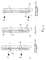
- Fig. 4a bis Fig. 4c
- unterschiedliche Kupplungsstellungen,
- Fig. 5
- in schematischer Darstellung einen Teil eines Getriebezuges des Differentialantriebes mit der erfindungsgemäßen Kupplungseinrichtung.
Claims (16)
- Kupplungseinrichtung einer Getriebeanordnung eines Fahrzeuges, vorzugsweise eines Kraftfahrzeuges, mit zwei Kupplungen, mit denen durch wahlweise Betätigung das Antriebsmoment einer Eingangswelle auf wenigstens zwei Abtriebswellen aufteilbar ist,
dadurch gekennzeichnet, daß die beiden Kupplungen (18, 19) wenigstens teilweise ineinander gesetzt sind. - Einrichtung nach Anspruch 1,
dadurch gekennzeichnet, daß die beiden Kupplungen (18, 19) koaxial zueinander liegen. - Einrichtung nach Anspruch 1 oder 2,
dadurch gekennzeichnet, daß die beiden Kupplungen (18, 19) gleiche axiale Länge haben und vorteilhaft jeweils als ringförmige Lamellenblöcke ausgebildet sind. - Kupplungseinrichtung, insbesondere nach einem der Ansprüche 1 bis 3,
dadurch gekennzeichnet, daß die beiden Kupplungen (18, 19) einen gemeinsamen Kupplungsträger (33) aufweisen. - Einrichtung nach Anspruch 4,
dadurch gekennzeichnet, daß die eine Kupplung (18) den Kupplungsträger (33) umgibt, der vorteilhaft die andere Kupplung (19) umgibt. - Einrichtung nach Anspruch 4 oder 5,
dadurch gekennzeichnet, daß der Kupplungsträger (33) einen zylindrischen Mantel (34) aufweist, der zwischen den beiden Kupplungen (18, 19) liegt. - Kupplungseinrichtung, insbesondere nach einem der Ansprüche 1 bis 6,
dadurch gekennzeichnet, daß zur Betätigung der Kupplungen (18, 19) ein gemeinsamer Stellantrieb (5) vorgesehen ist. - Einrichtung nach Anspruch 7,
dadurch gekennzeichnet, daß der Stellantrieb (5) ein Elektromotor ist. - Einrichtung nach Anspruch 7 oder 8,
dadurch gekennzeichnet, daß ein Ritzel (4) des Stellantriebes (5) mit einem vorteilhaft durch eine Kurvenscheibe gebildeten Antriebselement (1) in Eingriff ist. - Einrichtung nach Anspruch 9,
dadurch gekennzeichnet, daß das Antriebselement (1) Laufbahnen (12, 13), vorzugsweise Ringnuten, für Steuerelemente (14, 15) aufweist, die vorteilhaft durch Kugeln gebildet sind. - Einrichtung nach einem der Ansprüche 1 bis 10,
dadurch gekennzeichnet, daß jeder Kupplung (18, 19) ein Betätigungselement (16, 17) zugeordnet ist, die vorteilhaft Steigungsglieder (20, 21) aufweisen, die mit den Steuerelementen (14, 15) zusammenwirken. - Einrichtung nach Anspruch 11,
dadurch gekennzeichnet, daß die Steigungsglieder (20, 21) Vertiefungen in den Betätigungselementen (16, 17) sind. - Einrichtung nach Anspruch 11 oder 12,
dadurch gekennzeichnet, daß die Steigungsglieder (20, 21) einen Freilaufbereich (22, 24) aufweisen, in dem die Steigung Null ist, und daß vorteilhaft an den Freilaufbereich (22, 24) ein eine Steigung aufweisender Verstellbereich (23, 25) anschließt. - Einrichtung nach einem der Ansprüche 11 bis 13,
dadurch gekennzeichnet, daß die Steigungsglieder (20, 21) der vorteilhaft in einer gemeinsamen Ebene liegenden Betätigungselemente (16, 17) entgegengesetzt zueinander angeordnet sind. - Einrichtung nach einem der Ansprüche 11 bis 14,
dadurch gekennzeichnet, daß die Betätigungselemente (16, 17) unabhängig voneinander betätigbar sind. - Einrichtung nach einem der Ansprüche 11 bis 15,
dadurch gekennzeichnet, daß die Betätigungselemente (16, 17) über jeweils wenigstens ein Druckstück (26, 27) auf die Kupplung (18, 19) einwirken.
Applications Claiming Priority (2)
| Application Number | Priority Date | Filing Date | Title |
|---|---|---|---|
| DE102004023792 | 2004-05-07 | ||
| DE102004023792A DE102004023792A1 (de) | 2004-05-07 | 2004-05-07 | Kupplungseinrichtung einer Getriebeanordnung eines Fahrzeuges, vorzugsweise eines Kraftfahrzeuges |
Publications (2)
| Publication Number | Publication Date |
|---|---|
| EP1593540A2 true EP1593540A2 (de) | 2005-11-09 |
| EP1593540A3 EP1593540A3 (de) | 2006-08-02 |
Family
ID=34935138
Family Applications (1)
| Application Number | Title | Priority Date | Filing Date |
|---|---|---|---|
| EP05008117A Withdrawn EP1593540A3 (de) | 2004-05-07 | 2005-04-14 | Kupplingseinrichtung einer Getriebeanordnung eines Fahrzeuges, vorzugsweise eines Kraftfahrzeuges |
Country Status (2)
| Country | Link |
|---|---|
| EP (1) | EP1593540A3 (de) |
| DE (1) | DE102004023792A1 (de) |
Cited By (4)
| Publication number | Priority date | Publication date | Assignee | Title |
|---|---|---|---|---|
| WO2007034208A1 (en) * | 2005-09-26 | 2007-03-29 | Ricardo Uk Ltd. | Control assembly |
| FR2897405A1 (fr) * | 2006-02-14 | 2007-08-17 | Renault Sas | Dispositif d'embrayage double multidisque pour boite de vitesses de vehicule automobile, et boite de vitesses associee. |
| WO2007138006A1 (de) * | 2006-05-30 | 2007-12-06 | Zf Friedrichshafen Ag | Getriebeeinheit zur führung eines antriebsmomentes von einer antriebswelle auf zwei abtriebswellen |
| WO2010078937A1 (de) * | 2008-12-19 | 2010-07-15 | Gkn Driveline International Gmbh | Antriebsanordung |
Families Citing this family (7)
| Publication number | Priority date | Publication date | Assignee | Title |
|---|---|---|---|---|
| DE102007014831B4 (de) * | 2006-12-21 | 2020-07-30 | Borg Warner Inc. | Kupplungsaktuatorik mit einer Unterstützungseinrichtung und Kupplung mit einer solchen Kupplungsaktuatorik |
| DE102007016211B4 (de) | 2007-04-04 | 2019-03-07 | Schaeffler Technologies AG & Co. KG | Synchronisiereinrichtung für ein Schaltgetriebe |
| DE102009031249B4 (de) | 2009-07-01 | 2011-06-01 | Manfred Schindler | Kupplungs-Brems-Einheit und Doppelkupplung mit Kugel-Rampen-Betätigung |
| DE102013021947A1 (de) * | 2013-12-20 | 2015-06-25 | GM Global Technology Operations LLC (n. d. Gesetzen des Staates Delaware) | Schaltgetriebe und Kupplungsbaugruppe dafür |
| DE102016220696A1 (de) | 2016-10-21 | 2018-04-26 | Zf Friedrichshafen Ag | Betätigungseinrichtung zur Betätigung zweier Schaltelemente eines Getriebes |
| WO2021038266A1 (ja) * | 2019-08-28 | 2021-03-04 | 日産自動車株式会社 | 動力伝達装置 |
| DE102020211973A1 (de) * | 2020-09-24 | 2022-03-24 | Zf Friedrichshafen Ag | Betätigungsvorrichtung für ein Getriebe |
Family Cites Families (6)
| Publication number | Priority date | Publication date | Assignee | Title |
|---|---|---|---|---|
| IT1292384B1 (it) * | 1997-06-19 | 1999-02-08 | Baruffaldi Spa | Dispositivo di trasmissione del moto a frizione elettromagnetica e rotismo epicicloidale per ventole di autoveicolo |
| JP4163345B2 (ja) * | 1999-09-24 | 2008-10-08 | 本田技研工業株式会社 | 駆動力配分装置における電磁クラッチ構造 |
| DE10119509A1 (de) * | 2001-04-21 | 2002-10-24 | Zf Sachs Ag | Kupplungssystem mit einer vermittels elektrostatischer Kräfte betätigbaren Kupplungseinrichtung |
| JP3917390B2 (ja) * | 2001-07-06 | 2007-05-23 | 株式会社日立製作所 | 発電電動装置 |
| DE10160026B9 (de) * | 2001-12-06 | 2008-06-12 | Gkn Driveline International Gmbh | Betätigungsmechanismus zur Axialverstellung mit doppelter Funktion |
| US6699151B2 (en) * | 2002-03-27 | 2004-03-02 | Torque-Traction Technologies, Inc. | Solenoid valve controlled all-wheel drive hydraulic coupling assembly |
-
2004
- 2004-05-07 DE DE102004023792A patent/DE102004023792A1/de not_active Ceased
-
2005
- 2005-04-14 EP EP05008117A patent/EP1593540A3/de not_active Withdrawn
Non-Patent Citations (1)
| Title |
|---|
| None |
Cited By (7)
| Publication number | Priority date | Publication date | Assignee | Title |
|---|---|---|---|---|
| WO2007034208A1 (en) * | 2005-09-26 | 2007-03-29 | Ricardo Uk Ltd. | Control assembly |
| FR2897405A1 (fr) * | 2006-02-14 | 2007-08-17 | Renault Sas | Dispositif d'embrayage double multidisque pour boite de vitesses de vehicule automobile, et boite de vitesses associee. |
| WO2007093720A1 (fr) * | 2006-02-14 | 2007-08-23 | Renault S.A.S. | Dispositif d ' embrayage double multidisque pour boite de vitesses de vehicule automobile |
| WO2007138006A1 (de) * | 2006-05-30 | 2007-12-06 | Zf Friedrichshafen Ag | Getriebeeinheit zur führung eines antriebsmomentes von einer antriebswelle auf zwei abtriebswellen |
| WO2010078937A1 (de) * | 2008-12-19 | 2010-07-15 | Gkn Driveline International Gmbh | Antriebsanordung |
| JP2012512996A (ja) * | 2008-12-19 | 2012-06-07 | ゲー カー エヌ ドライブライン インターナショナル ゲゼルシャフト ミット ベシュレンクテル ハフツング | 駆動アッセンブリ |
| US8678971B2 (en) | 2008-12-19 | 2014-03-25 | Gkn Driveline International Gmbh | Drive assembly |
Also Published As
| Publication number | Publication date |
|---|---|
| DE102004023792A1 (de) | 2005-12-08 |
| EP1593540A3 (de) | 2006-08-02 |
Similar Documents
| Publication | Publication Date | Title |
|---|---|---|
| DE102008063904B4 (de) | Antriebsanordnung | |
| DE19703241C2 (de) | Kupplungsanordnung mit einem Planetengetriebe | |
| DE3787552T2 (de) | Zusatzgetriebe für Kraftfahrzeuge. | |
| DE3802368C2 (de) | Antrieb für ein Fahrzeug mit Vierradantrieb | |
| DE102005063390B4 (de) | Getriebeanordnung zur variablen Drehmomentverteilung | |
| EP0264579B1 (de) | Sperrbares Ausgleichsgetriebe | |
| AT503359B1 (de) | Getriebemodul zur variablen drehmomentverteilung | |
| DE10251467A1 (de) | Getriebemodul für Kupplungsbetätigungseinrichtung einer Differentialanordnung | |
| DE1780154B2 (de) | Stufenlos einstellbarer Radnabenantrieb für Fahrzeuge | |
| EP1593540A2 (de) | Kupplingseinrichtung einer Getriebeanordnung eines Fahrzeuges, vorzugsweise eines Kraftfahrzeuges | |
| DE102006001334B3 (de) | Getriebeanordnung zur variablen Drehmomentverteilung | |
| EP3622189B1 (de) | Doppelkupplungseinheit und elektroantrieb mit einer solchen doppelkupplungseinheit | |
| DE10335507A1 (de) | Selektiv betätigtes Verteilergetriebe | |
| EP3882478B1 (de) | Antriebsstrang mit einer beweglichen kupplung zwischen einer motorwelle und einer eingangswelle eines schaltgetriebes | |
| DE202005017525U1 (de) | Reibungskupplung | |
| DE102006042477A1 (de) | Elektromotorischer Aktuator zur Auslenkung eines Kraftfahrzeugteils | |
| DE102014201250A1 (de) | Vorrichtung zur schaltbaren Kopplung einer Basis mit zwei koaxialen Wellen | |
| DE102006006640B3 (de) | Umlenkgetriebe zur Betätigung einer Lamellenkupplung | |
| DE102006046712A1 (de) | Parksperrenvorrichtung für ein Kraftfahrzeug | |
| DE69907697T2 (de) | Untersetzunggetriebe mit eingebauter Bremse für Nutzfahrzeuuge | |
| DE10302506A1 (de) | Elektromagnetisch betätigbare Doppelkupplungs-Bremskombination | |
| DE102014226496A1 (de) | Schaltvorrichtung für ein Tretrad | |
| WO2022053141A1 (de) | Parksperreneinheit für einen antriebsstrang eines kraftfahrzeugs und getriebeanordnung mit einer solchen parksperreneinheit | |
| DE102019100368A1 (de) | Stirnraddifferentialgetriebe | |
| DE102019100366A1 (de) | Stirnraddifferentialgetriebe |
Legal Events
| Date | Code | Title | Description |
|---|---|---|---|
| PUAI | Public reference made under article 153(3) epc to a published international application that has entered the european phase |
Free format text: ORIGINAL CODE: 0009012 |
|
| AK | Designated contracting states |
Kind code of ref document: A2 Designated state(s): AT BE BG CH CY CZ DE DK EE ES FI FR GB GR HU IE IS IT LI LT LU MC NL PL PT RO SE SI SK TR |
|
| AX | Request for extension of the european patent |
Extension state: AL BA HR LV MK YU |
|
| PUAL | Search report despatched |
Free format text: ORIGINAL CODE: 0009013 |
|
| AK | Designated contracting states |
Kind code of ref document: A3 Designated state(s): AT BE BG CH CY CZ DE DK EE ES FI FR GB GR HU IE IS IT LI LT LU MC NL PL PT RO SE SI SK TR |
|
| AX | Request for extension of the european patent |
Extension state: AL BA HR LV MK YU |
|
| RIC1 | Information provided on ipc code assigned before grant |
Ipc: F16D 21/06 20060101ALI20060629BHEP Ipc: B60K 17/02 20060101AFI20050822BHEP |
|
| AKX | Designation fees paid | ||
| STAA | Information on the status of an ep patent application or granted ep patent |
Free format text: STATUS: THE APPLICATION IS DEEMED TO BE WITHDRAWN |
|
| 18D | Application deemed to be withdrawn |
Effective date: 20070203 |
|
| REG | Reference to a national code |
Ref country code: DE Ref legal event code: 8566 |