EP1593540A2 - Clutch device of a transmission arrangement of a vehicle particularly a motor vehicle - Google Patents
Clutch device of a transmission arrangement of a vehicle particularly a motor vehicle Download PDFInfo
- Publication number
- EP1593540A2 EP1593540A2 EP05008117A EP05008117A EP1593540A2 EP 1593540 A2 EP1593540 A2 EP 1593540A2 EP 05008117 A EP05008117 A EP 05008117A EP 05008117 A EP05008117 A EP 05008117A EP 1593540 A2 EP1593540 A2 EP 1593540A2
- Authority
- EP
- European Patent Office
- Prior art keywords
- clutches
- coupling
- advantageously
- carrier
- cam
- Prior art date
- Legal status (The legal status is an assumption and is not a legal conclusion. Google has not performed a legal analysis and makes no representation as to the accuracy of the status listed.)
- Withdrawn
Links
Images


Classifications
-
- F—MECHANICAL ENGINEERING; LIGHTING; HEATING; WEAPONS; BLASTING
- F16—ENGINEERING ELEMENTS AND UNITS; GENERAL MEASURES FOR PRODUCING AND MAINTAINING EFFECTIVE FUNCTIONING OF MACHINES OR INSTALLATIONS; THERMAL INSULATION IN GENERAL
- F16D—COUPLINGS FOR TRANSMITTING ROTATION; CLUTCHES; BRAKES
- F16D21/00—Systems comprising a plurality of actuated clutches
- F16D21/02—Systems comprising a plurality of actuated clutches for interconnecting three or more shafts or other transmission members in different ways
- F16D21/06—Systems comprising a plurality of actuated clutches for interconnecting three or more shafts or other transmission members in different ways at least two driving shafts or two driven shafts being concentric
-
- B—PERFORMING OPERATIONS; TRANSPORTING
- B60—VEHICLES IN GENERAL
- B60K—ARRANGEMENT OR MOUNTING OF PROPULSION UNITS OR OF TRANSMISSIONS IN VEHICLES; ARRANGEMENT OR MOUNTING OF PLURAL DIVERSE PRIME-MOVERS IN VEHICLES; AUXILIARY DRIVES FOR VEHICLES; INSTRUMENTATION OR DASHBOARDS FOR VEHICLES; ARRANGEMENTS IN CONNECTION WITH COOLING, AIR INTAKE, GAS EXHAUST OR FUEL SUPPLY OF PROPULSION UNITS IN VEHICLES
- B60K17/00—Arrangement or mounting of transmissions in vehicles
- B60K17/34—Arrangement or mounting of transmissions in vehicles for driving both front and rear wheels, e.g. four wheel drive vehicles
- B60K17/344—Arrangement or mounting of transmissions in vehicles for driving both front and rear wheels, e.g. four wheel drive vehicles having a transfer gear
- B60K17/346—Arrangement or mounting of transmissions in vehicles for driving both front and rear wheels, e.g. four wheel drive vehicles having a transfer gear the transfer gear being a differential gear
- B60K17/3462—Arrangement or mounting of transmissions in vehicles for driving both front and rear wheels, e.g. four wheel drive vehicles having a transfer gear the transfer gear being a differential gear with means for changing distribution of torque between front and rear wheels
-
- B—PERFORMING OPERATIONS; TRANSPORTING
- B60—VEHICLES IN GENERAL
- B60K—ARRANGEMENT OR MOUNTING OF PROPULSION UNITS OR OF TRANSMISSIONS IN VEHICLES; ARRANGEMENT OR MOUNTING OF PLURAL DIVERSE PRIME-MOVERS IN VEHICLES; AUXILIARY DRIVES FOR VEHICLES; INSTRUMENTATION OR DASHBOARDS FOR VEHICLES; ARRANGEMENTS IN CONNECTION WITH COOLING, AIR INTAKE, GAS EXHAUST OR FUEL SUPPLY OF PROPULSION UNITS IN VEHICLES
- B60K23/00—Arrangement or mounting of control devices for vehicle transmissions, or parts thereof, not otherwise provided for
- B60K23/04—Arrangement or mounting of control devices for vehicle transmissions, or parts thereof, not otherwise provided for for differential gearing
-
- B—PERFORMING OPERATIONS; TRANSPORTING
- B60—VEHICLES IN GENERAL
- B60K—ARRANGEMENT OR MOUNTING OF PROPULSION UNITS OR OF TRANSMISSIONS IN VEHICLES; ARRANGEMENT OR MOUNTING OF PLURAL DIVERSE PRIME-MOVERS IN VEHICLES; AUXILIARY DRIVES FOR VEHICLES; INSTRUMENTATION OR DASHBOARDS FOR VEHICLES; ARRANGEMENTS IN CONNECTION WITH COOLING, AIR INTAKE, GAS EXHAUST OR FUEL SUPPLY OF PROPULSION UNITS IN VEHICLES
- B60K23/00—Arrangement or mounting of control devices for vehicle transmissions, or parts thereof, not otherwise provided for
- B60K23/08—Arrangement or mounting of control devices for vehicle transmissions, or parts thereof, not otherwise provided for for changing number of driven wheels, for switching from driving one axle to driving two or more axles
- B60K23/0808—Arrangement or mounting of control devices for vehicle transmissions, or parts thereof, not otherwise provided for for changing number of driven wheels, for switching from driving one axle to driving two or more axles for varying torque distribution between driven axles, e.g. by transfer clutch
-
- F—MECHANICAL ENGINEERING; LIGHTING; HEATING; WEAPONS; BLASTING
- F16—ENGINEERING ELEMENTS AND UNITS; GENERAL MEASURES FOR PRODUCING AND MAINTAINING EFFECTIVE FUNCTIONING OF MACHINES OR INSTALLATIONS; THERMAL INSULATION IN GENERAL
- F16D—COUPLINGS FOR TRANSMITTING ROTATION; CLUTCHES; BRAKES
- F16D28/00—Electrically-actuated clutches
-
- F—MECHANICAL ENGINEERING; LIGHTING; HEATING; WEAPONS; BLASTING
- F16—ENGINEERING ELEMENTS AND UNITS; GENERAL MEASURES FOR PRODUCING AND MAINTAINING EFFECTIVE FUNCTIONING OF MACHINES OR INSTALLATIONS; THERMAL INSULATION IN GENERAL
- F16D—COUPLINGS FOR TRANSMITTING ROTATION; CLUTCHES; BRAKES
- F16D21/00—Systems comprising a plurality of actuated clutches
- F16D21/02—Systems comprising a plurality of actuated clutches for interconnecting three or more shafts or other transmission members in different ways
- F16D21/06—Systems comprising a plurality of actuated clutches for interconnecting three or more shafts or other transmission members in different ways at least two driving shafts or two driven shafts being concentric
- F16D2021/0638—Electrically actuated multiple lamellae clutches
-
- F—MECHANICAL ENGINEERING; LIGHTING; HEATING; WEAPONS; BLASTING
- F16—ENGINEERING ELEMENTS AND UNITS; GENERAL MEASURES FOR PRODUCING AND MAINTAINING EFFECTIVE FUNCTIONING OF MACHINES OR INSTALLATIONS; THERMAL INSULATION IN GENERAL
- F16D—COUPLINGS FOR TRANSMITTING ROTATION; CLUTCHES; BRAKES
- F16D27/00—Magnetically- or electrically- actuated clutches; Control or electric circuits therefor
- F16D27/004—Magnetically- or electrically- actuated clutches; Control or electric circuits therefor with permanent magnets combined with electromagnets
-
- F—MECHANICAL ENGINEERING; LIGHTING; HEATING; WEAPONS; BLASTING
- F16—ENGINEERING ELEMENTS AND UNITS; GENERAL MEASURES FOR PRODUCING AND MAINTAINING EFFECTIVE FUNCTIONING OF MACHINES OR INSTALLATIONS; THERMAL INSULATION IN GENERAL
- F16H—GEARING
- F16H25/00—Gearings comprising primarily only cams, cam-followers and screw-and-nut mechanisms
- F16H25/18—Gearings comprising primarily only cams, cam-followers and screw-and-nut mechanisms for conveying or interconverting oscillating or reciprocating motions
- F16H25/186—Gearings comprising primarily only cams, cam-followers and screw-and-nut mechanisms for conveying or interconverting oscillating or reciprocating motions with reciprocation along the axis of oscillation
Definitions
- the invention relates to a coupling device of a transmission arrangement a vehicle, preferably a motor vehicle, according to the preamble of claim 1.
- the invention is based on the object, the generic coupling device in such a way that the gear arrangement has little installation space needed.
- the two clutches at least partially intertwined.
- Advantageous are the two Fully assembled couplings, so that the axial length of the Coupling device essentially only by the axial length of a coupling is determined.
- the coupling device and the transmission only a small axial installation length, so that this transmission can be used excellently in tight installation conditions.
- the coupling device described below is part of a Differential drive used in four-wheel drives of motor vehicles and optimally distributes the torque to the respective wheels becomes. Such differential drives are known and therefore are not explained in detail.
- the coupling device With the coupling device, the torque split on two side shafts of the four-wheel drive via a planetary gear become.
- the coupling device has a cam 1, the rotationally fixed sits on an inner disk carrier 2. He is designed as a hollow carrier.
- the cam 1 is provided on the circumference with a toothing 3, in the a pinion 4 of an electric motor 5 engages.
- the cam 1 is supported via a bearing 6 on the bottom 7 of a housing 8 from. It's about a part its circumference provided with a jacket 9, which the cam 1 with partially surrounds radial distance.
- the housing jacket 9 approximately over 180 ° (FIG. 2).
- the Electric motor 5 attached on the housing 8 is the Electric motor 5 attached.
- the pinion 4 protrudes through a peripheral depression 10 (Fig. 2) of the bottom 7 of the housing 8.
- the teeth 3 of the cam 1 is provided on a projection 11 (Fig. 2), which only extends over part of the circumference of the cam 1.
- the lead 11 is in the circumferential direction of the cam 1 so long that the coupling device be reliably operated in a manner to be described can.
- the projection 11 extends over an angular range of about 60 °.
- the projection 11 is above the Housing 8 radially over.
- the housing jacket 8 is provided so that it Rotation of the cam 1 when actuated by means of the electric motor. 5 not disabled.
- the projection 11 can therefore be in the area between the ends of the housing shell 9 rotate freely.
- the cam 1 is on its side facing away from the electric motor 5 side two concentric annular grooves 12 and 13 provided, the distance from each other have and have approximately semicircular cross-section.
- the ring grooves 12, 13 engage balls 14, 15 which extend beyond the circumference of the respective ones Ring grooves 12, 13 are arranged distributed.
- the cam 1 are an annular ball ramp 16 and a disk-shaped Ball ramp 17 opposite.
- the two ball ramps 16, 17 are located in a common plane (Fig. 1).
- the annular ball ramp 16 lies on the circumference of the disc-shaped ball ramp 17, which in turn on the inner disk carrier 2 is mounted.
- the two ball ramps 16, 17 can be moved axially against each other slightly to a radial outer fin block 18 or a radially inner fin block 19 too actuate.
- the two ball ramps 16, 17 are, as shown in FIG. 3, with over its circumference distributed arranged recesses 20, 21 provided. They each extend in the circumferential direction of the ball ramps 16, 17.
- the recesses 20 of the outer ball ramp 16 are longer than the recesses 21 of the radially inner Ball ramp 17.
- the wells 20 are each formed the same and have a about half the length extending freewheel area 22, in which the grooves 20 have constant depth. At this freewheel area 22, which has constant width over its length, closes an adjustment range 23, which tapers towards its free end and in which the depth the recess 20 decreases steadily towards the free end.
- the recesses 21 of the radially inner ball ramp 17 also have a Freewheel area 24, in which the recesses 21 constant width and depth to have.
- To the freewheel area 24 includes an adjustment 25, which is tapered towards its free end and its width and depth in Direction towards the free end steadily decreases.
- the depressions 21, the same are formed, are twisted by 180 ° compared to the wells 20 arranged.
- each of the recesses 20, 21 each engage a ball 14 and 15, respectively.
- the cam 1 means of the pinion 4 in the desired direction so rotated that the balls 14th or 15 from the respective freewheel area 22, 24 into the adjustment area 23, 25 of the ball ramps 16, 17 arrive.
- the radially outer or the radially inner ball ramp 16, 17 axially displaced, whereby about plungers 26, 27 of the respective slat block 18 and 19 compressed becomes. This will be described in detail later.
- the pressure pieces 26, 27 protrude through openings 31, 32, which on a plate carrier 33 are provided. He has a cylindrical shell 34, whose Axis coincides with the axis of the inner disk carrier 2.
- the coat 34 surrounds the inner fin block 19, which on the inner wall of the shell 34 abuts and is mounted on the inner disk carrier 2.
- the jacket 34 is surrounded by the outer fin block 18, which on the outside of the Carrier 34 is present.
- the two lamella blocks 18, 19 consist of annular, superimposed annular lamellae.
- the two equally long lamellar blocks 18, 19 are at the common Plate carrier 33 held.
- the outer fin block 18 is located on a Bottom 39 of an outer disk carrier 40, the left output of the Differential gear forms.
- the radially lying bottom 39 goes into an in Direction of the cam 1 extending cylinder shell 41st over which surrounds the outer fin block 18 with low radial clearance and surrounded by the cylinder jacket 37 of the housing 38 with low radial clearance is.
- the cylinder jacket 37 projects beyond the cylinder jacket 41, the distance from the radial flange 36 has.
- On the outer fin block 18 is located a pressure plate 42, the same radial width as the lamella block 18 has.
- the plungers 26 exercise via an intermediate disc 43 a Force on the pressure plate 42 on.
- a pressure plate 44 On the inner fin block 19 is a pressure plate 44, on the the pressure pieces 27 act via an intermediate disc 45.
- the two pressure washers 42, 44 are at the same height in a radial plane.
- the outer pressure plate 42 has at the outer edge a thin annular wall 46, with which it surrounds the outer washer 43.
- the pressure plate 42 abuts against the inner wall of the cylinder jacket 41 and is therefore flawless radially centered. From the jacket 34 of the plate carrier 33 has the outer Pressure disk 42 small radial distance.
- the inner pressure washer 44 has a thin annular wall at the radially inner edge 47, which rests against the inner disk carrier 2 and the inner washer 45 at the inner edge encloses.
- the bottom 39 of the outer disk carrier 40 has a thickened portion, on which the outer fin block 18 rests. This thickened area of the Bodens 39 goes into a thinner, radially inner floor area over, on which the cylinder jacket 34 of the disk carrier 33 with his Front side rests.
- the inner disk carrier 2 has a radial annular flange 48, which is advantageously integrally formed with the inner disk carrier 2 and surrounded by the jacket 34 of the disk carrier 33.
- the ring flange 48 extends to the inner wall of the shell 34 and is located above a bearing 49 at the thinner portion of the bottom 39 of the outer disk carrier 40 at.
- the radially extending bottom 39 connects the cylinder jacket 41 with a Sleeve 50, with the outer disk carrier 40 on the inner disk carrier. 2 rests.
- the sleeve 50 is advantageously formed integrally with the bottom 39.
- a sleeve 51 of the housing 38 On the sleeve 50 of the outer disk carrier 40 is a sleeve 51 of the housing 38 on.
- the sleeve 51 is through a radial bottom 52 with the cylinder jacket 37 of the housing 38 connected.
- the outer disk carrier 40 is with its bottom 39 with an intermediate layer a bearing 53 rotatably supported on the bottom 52 of the housing 38. Of the Diameter of the bearing 53 is greater than the diameter of the bearing 49th The bearing 53 surrounds the casing 34 of the disk carrier 33, in the axial direction seen, by far. The bearing 49 is located, viewed in the axial direction, within the jacket 34 of the disc carrier 33.
- the bottom 52 of the housing 38 is supported via a bearing 54 on a support disk 55, which is arranged on the sleeve 51 of the housing 38.
- the lamella blocks 18, 19 protected housed in the housing 38.
- the common plate carrier 33 is provided so that a constructive simple construction results. Since the two lamellar blocks 18, 19 coaxial lie to each other and are juxtaposed, the coupling device is characterized by only a small axial length. She can do it be used in cramped installation conditions in the vehicle.
- the lamellar blocks 18, 19 can be actuated independently of each other, to the drive torque to the respective wheels to the desired extent to distribute.
- Fig. 4b shows the neutral position of the coupling device. She is characterized in that the balls 14, 15 between the cam 1 and the two ball ramps 16, 17 in the freewheel area 22, 24th the recesses 20, 21 of the ball ramps are located. The torque is distributed equally on both side shafts of the differential gear.
- Fig. 5 the left side shaft 57 is shown. The side shaft 57 is over a bevel gear 58 in engagement with a differential case or differential carrier 59.
- the two lamellae blocks 18, 19, which the couplings form, are out of action. This will drive torque to both Distributed side shafts of the differential gear in half.
- the differential case 59 is part of a planetary gear 60.
- the differential case 59 forms the planet carrier that drives the left side shaft 57.
- the sun gear 61 the planetary gear 60 is rotatably connected to the inner disk carrier 2 and forms the right side wave.
- the planet carrier or the differential housing 59 drives a countershaft 62, which is parallel to the hollow shaft 2, which is formed by the inner disk carrier 2.
- the pinion 4 of the Servomotor 5 is rotated in one direction, so that the cam 1 in the Required direction limited rotated about its axis.
- the ball ramp 16 exercises on the plungers 26 and the pressure plate 42 an axial force on the plate block 18 from.
- These Force F is indicated in Fig. 4c by a corresponding arrow.
- the wells 20 and 21 of the two Ball ramps 16, 17 rotated by 180 ° to each other, wherein the outer recesses 20 of the ball ramp 16 in the circumferential direction substantially are longer than the recesses 21 of the inner ball ramp 17.
- the in Circumferentially measured length of the freewheeling area 22 of the wells 20 corresponds approximately to the total length of the recesses 21 of the inner Ball ramp 17.
- the balls 14, 15 are arranged in the recesses 20, 21, that the outer balls 40 still in the freewheel region 22 of the wells 20 are when the radially inner balls 15 in the adjustment 25 of the wells 21 are located.
- the drive is via the bevel gear 58 on the formed as a ring gear Differential case 59. He is about the translation stage with the common plate carrier 33 for the outer and the inner plate block 18, 19 connected and turns faster. By closing the lamella blocks 18 and 19 in the manner described the respective outside of the curve Rad (outside of the bend output) imprinted an additional torque.
Abstract
Description
Die Erfindung betrifft eine Kupplungseinrichtung einer Getriebeanordnung eines Fahrzeuges, vorzugsweise eines Kraftfahrzeuges, nach dem Oberbegriff des Anspruches 1.The invention relates to a coupling device of a transmission arrangement a vehicle, preferably a motor vehicle, according to the preamble of claim 1.
Es sind Getriebeanordnungen mit Kupplungseinrichtungen bei Vierradantrieben von Kraftfahrzeugen bekannt, bei denen durch Betätigung der Kupplungen das Antriebsdrehmoment der Antriebswelle unterschiedlich auf die Abtriebswellen aufgeteilt werden kann, je nach benötigtem Drehmoment an den jeweiligen angetriebenen Rädern. Die Kupplungen sind mit Abstand hintereinander angeordnet, so daß die Kupplungseinrichtung und damit das gesamte Getriebe eine entsprechende axiale Länge aufweist. Darum kann dieses Getriebe nicht dort eingesetzt werden, wo die Platzverhältnisse eng sind.There are gear arrangements with coupling devices in four-wheel drives known of motor vehicles, in which by actuation of the clutches the drive torque of the drive shaft different on the output shafts can be divided, depending on the required torque to the respective driven wheels. The couplings are at a distance one behind the other arranged so that the coupling device and thus the entire Transmission has a corresponding axial length. That's why this can be Gearboxes are not used where space is tight are.
Der Erfindung liegt die Aufgabe zugrunde, die gattungsgemäße Kupplungseinrichtung so auszubilden, daß die Getriebeanordnung nur wenig Einbauraum benötigt.The invention is based on the object, the generic coupling device in such a way that the gear arrangement has little installation space needed.
Diese Aufgabe wird bei der gattungsgemäßen Kupplungseinrichtung erfindungsgemäß mit den kennzeichnenden Merkmalen des Anspruches 1 gelöst.This object is according to the invention in the generic coupling device solved with the characterizing features of claim 1.
Bei der erfindungsgemäßen Kupplungseinrichtung sind die beiden Kupplungen wenigstens teilweise ineinander gesetzt. Vorteilhaft sind die beiden Kupplungen vollständig ineinander gesetzt, so daß die axiale Länge der Kupplungseinrichtung im wesentlichen lediglich durch die axiale Länge der einen Kupplung bestimmt wird. Dadurch hat die Kupplungseinrichtung und damit das Getriebe nur eine geringer axiale Einbaulänge, so daß dieses Getriebe hervorragend bei engen Einbauverhältnissen eingesetzt werden kann.In the coupling device according to the invention, the two clutches at least partially intertwined. Advantageous are the two Fully assembled couplings, so that the axial length of the Coupling device essentially only by the axial length of a coupling is determined. As a result, the coupling device and Thus, the transmission only a small axial installation length, so that this transmission can be used excellently in tight installation conditions.
Weitere Merkmale der Erfindung ergeben sich aus den weiteren Ansprüchen, der Beschreibung und den Zeichnungen.Further features of the invention will become apparent from the further claims, the description and the drawings.
Die Erfindung wird anhand eines in den Zeichnungen dargestellten Ausführungsbeispieles näher erläutert. Es zeigen
- Fig. 1
- im Axialschnitt eine erfindungsgemäße Kupplungseinrichtung für ein Differentialgetriebe,
- Fig. 2
- die erfindungsgemäße Kupplungseinrichtung gemäß Fig. 1 in Explosivdarstellung,
- Fig. 3
- eine Stirnansicht einer Kugelrampe der erfindungsgemäßen Kupplungseinrichtung,
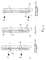
- Fig. 4a bis Fig. 4c
- unterschiedliche Kupplungsstellungen,
- Fig. 5
- in schematischer Darstellung einen Teil eines Getriebezuges des Differentialantriebes mit der erfindungsgemäßen Kupplungseinrichtung.
- Fig. 1
- in axial section a coupling device according to the invention for a differential gear,
- Fig. 2
- the coupling device according to the invention according to FIG. 1 in an exploded view,
- Fig. 3
- an end view of a ball ramp of the coupling device according to the invention,
- Fig. 4a to Fig. 4c
- different coupling positions,
- Fig. 5
- in a schematic representation of a part of a gear train of the differential drive with the coupling device according to the invention.
Die im folgenden beschriebene Kupplungseinrichtung ist Bestandteil eines
Differentialantriebes, der bei Vierradantrieben von Kraftfahrzeugen verwendet
wird und mit dem das Drehmoment auf die jeweiligen Räder optimal verteilt
wird. Solche Differentialantriebe sind bekannt und werden darum auch
nicht näher erläutert. Mit der Kupplungseinrichtung kann das Drehmoment
auf zwei Seitenwellen des Vierradantriebes über ein Planetengetriebe aufgeteilt
werden. Die Kupplungseinrichtung hat eine Kurvenscheibe 1, die drehfest
auf einem Innenlamellenträger 2 sitzt. Er ist als Hohlträger ausgebildet.
Die Kurvenscheibe 1 ist am Umfang mit einer Verzahnung 3 versehen, in die
ein Ritzel 4 eines Elektromotors 5 eingreift. Die Kurvenscheibe 1 stützt sich
über ein Lager 6 am Boden 7 eines Gehäuses 8 ab. Es ist über einen Teil
seines Umfanges mit einem Mantel 9 versehen, der die Kurvenscheibe 1 mit
radialem Abstand teilweise umgibt. Im Ausführungsbeispiel erstreckt sich
der Gehäusemantel 9 etwa über 180° (Fig. 2). Auf dem Gehäuse 8 ist der
Elektromotor 5 befestigt. Das Ritzel 4 ragt durch eine umfangsseitige Vertiefung
10 (Fig. 2) des Bodens 7 des Gehäuses 8. Die Verzahnung 3 der Kurvenscheibe
1 ist an einem Vorsprung 11 vorgesehen (Fig. 2), der sich nur
über einen Teil des Umfanges der Kurvenscheibe 1 erstreckt. Der Vorsprung
11 ist in Umfangsrichtung der Kurvenscheibe 1 so lang, daß die Kupplungseinrichtung
in noch zu beschreibender Weise zuverlässig betätigt werden
kann. Im dargestellten Ausführungsbeispiel erstreckt sich der Vorsprung 11
über einen Winkelbereich von etwa 60°. Der Vorsprung 11 steht über das
Gehäuse 8 radial über. Der Gehäusemantel 8 ist so vorgesehen, daß er die
Drehung der Kurvenscheibe 1 bei Betätigung mittels des Elektromotors 5
nicht behindert. Der Vorsprung 11 kann darum im Bereich zwischen den Enden
des Gehäusemantels 9 ungehindert drehen.The coupling device described below is part of a
Differential drive used in four-wheel drives of motor vehicles
and optimally distributes the torque to the respective wheels
becomes. Such differential drives are known and therefore are
not explained in detail. With the coupling device, the torque
split on two side shafts of the four-wheel drive via a planetary gear
become. The coupling device has a cam 1, the rotationally fixed
sits on an
Die Kurvenscheibe 1 ist an ihrer vom Elektromotor 5 abgewandten Seite mit
zwei konzentrischen Ringnuten 12 und 13 versehen, die Abstand voneinander
haben und etwa halbkreisförmigen Querschnitt aufweisen. In die Ringnuten
12, 13 greifen Kugeln 14, 15 ein, die über den Umfang der jeweiligen
Ringnuten 12, 13 verteilt angeordnet sind.The cam 1 is on its side facing away from the
Der Kurvenscheibe 1 liegen eine ringförmige Kugelrampe 16 und eine scheibenförmige
Kugelrampe 17 gegenüber. Die beiden Kugelrampen 16, 17 liegen
in einer gemeinsamen Ebene (Fig. 1). Die ringförmige Kugelrampe 16
liegt am Umfang der scheibenförmigen Kugelrampe 17, die ihrerseits auf
dem Innenlamellenträger 2 gelagert ist. Die beiden Kugelrampen 16, 17
können axial gegeneinander geringfügig bewegt werden, um einen radial
äußeren Lamellenblock 18 oder einen radial inneren Lamellenblock 19 zu
betätigen.The cam 1 are an
Die beiden Kugelrampen 16, 17 sind, wie Fig. 3 zeigt, mit über ihren Umfang
verteilt angeordneten Vertiefungen 20, 21 versehen. Sie erstrecken sich jeweils
in Umfangsrichtung der Kugelrampen 16, 17. Die Vertiefungen 20 der
äußeren Kugelrampe 16 sind länger als die Vertiefungen 21 der radial inneren
Kugelrampe 17. Die Vertiefungen 20 sind jeweils gleich ausgebildet und
haben einen etwa über die halbe Länge sich erstreckenden Freilaufbereich
22, in dem die Nuten 20 konstante Tiefe haben. An diesen Freilaufbereich
22, der über seine Länge konstante Breite hat, schließt ein Verstellbereich
23 an, der sich in Richtung auf sein freies Ende verjüngt und in dem die Tiefe
der Vertiefung 20 in Richtung auf das freie Ende stetig abnimmt.The two
Die Vertiefungen 21 der radial inneren Kugelrampe 17 haben ebenfalls einen
Freilaufbereich 24, in dem die Vertiefungen 21 konstante Breite und Tiefe
haben. An den Freilaufbereich 24 schließt ein Verstellbereich 25 an, der sich
in Richtung auf sein freies Ende verjüngt und dessen Breite und Tiefe in
Richtung auf das freie Ende stetig abnimmt. Die Vertiefungen 21, die gleich
ausgebildet sind, sind im Vergleich zu den Vertiefungen 20 um 180° verdreht
angeordnet.The recesses 21 of the radially
In jede der Vertiefungen 20, 21 greift jeweils eine Kugel 14 bzw. 15 ein. In
der Ausgangsstellung befinden sich die Kugeln 14, 15 im Freilaufbereich 22,
24 der Kugelrampen 16, 17. Zur Betätigung des Kupplungslamellenblocks
18, 19 wird in noch zu beschreibender Weise die Kurvenscheibe 1 mittels
des Ritzels 4 in der gewünschten Richtung so verdreht, daß die Kugeln 14
oder 15 aus dem jeweiligen Freilaufbereich 22, 24 in den Verstellbereich 23,
25 der Kugelrampen 16, 17 gelangen. Dementsprechend wird die radial äußere
oder die radial innere Kugelrampe 16, 17 axial verschoben, wodurch
über Druckstücke 26, 27 der jeweilige Lamellenblock 18 bzw. 19 zusammengedrückt
wird. Dies wird noch im einzelnen beschrieben werden.In each of the
An der von der Kurvenscheibe 1 abgewandten Seite liegen an den Kugelrampen
16, 17 zwei Druckringe 28 und 29 an, von denen der äußere Druckring
28 von einer dünnen Ringwand 30 der äußeren Kugelrampe 17 umgeben
wird. Durch diese Ringwand 30 wird der äußere Druckring 29 einwandfrei
zentriert. Der radial innere Druckring 29 ist der inneren Kugelrampe 17
zugeordnet. Am äußeren Druckring 28 liegen die Druckstücke 26 und am
inneren Druckring 29 die Druckstücke 27 an.At the side facing away from the cam 1 side are located on the ball ramps
16, 17, two pressure rings 28 and 29, of which the
Die Druckstücke 26, 27 ragen durch Öffnungen 31, 32, die an einem Lamellenträger
33 vorgesehen sind. Er hat einen zylindrischen Mantel 34, dessen
Achse mit der Achse des Innenlamellenträgers 2 zusammenfällt. Der Mantel
34 umgibt den inneren Lamellenblock 19, der an der Innenwand des Mantels
34 anliegt und auf dem Innenlamellenträger 2 gelagert ist. Der Mantel 34
wird vom äußeren Lamellenblock 18 umgeben, der an der Außenseite des
Trägers 34 anliegt. Die beiden Lamellenblöcke 18, 19 bestehen aus ringförmigen,
aufeinander liegenden Ringlamellen.The
An der der Kurvenscheibe 1 zugewandten Seite ist der Mantel 34 durch einen
Boden 35 geschlossen, der sich radial zum Innenlamellenträger 2 erstreckt
und in dem die Öffnungen 32 für die inneren Druckstücke 27 vorgesehen
sind. An dem der Kurvenscheibe 1 zugewandten Ende schließt an den
Mantel 34 ein ringförmiger Radialflansch 36 an, der in der gleichen Radialebene
wie der Boden 35 liegt und der die Öffnungen 31 für die Druckstücke
26 aufweist. Der Radialflansch 36 ist am äußeren Rand auf einem Zylindermantel
37 eines Gehäuses 38 befestigt, vorzugsweise angeschweißt. At the cam plate 1 side facing the
Die beiden gleich langen Lamellenblöcke 18, 19 sind an dem gemeinsamen
Lamellenträger 33 gehalten. Der äußere Lamellenblock 18 liegt auf einem
Boden 39 eines Außenlamellenträgers 40 auf, der den linken Abtrieb des
Differentialgetriebes bildet. Der radial liegende Boden 39 geht in einen in
Richtung auf die Kurvenscheibe 1 sich erstreckenden Zylindermantel 41
über, der den äußeren Lamellenblock 18 mit geringem Radialspiel umgibt
und vom Zylindermantel 37 des Gehäuses 38 mit geringem Radialspiel umgeben
ist. Der Zylindermantel 37 überragt den Zylindermantel 41, der Abstand
vom Radialflansch 36 hat. Auf dem äußeren Lamellenblock 18 liegt
eine Andruckscheibe 42 auf, die gleiche radiale Breite wie der Lamellenblock
18 hat. Die Druckstücke 26 üben über eine Zwischenscheibe 43 eine
Kraft auf die Andruckscheibe 42 auf.The two equally long lamellar blocks 18, 19 are at the
Auf dem inneren Lamellenblock 19 liegt eine Andruckscheibe 44 auf, auf die
die Druckstücke 27 über eine Zwischenscheibe 45 wirken. Die beiden Andruckscheiben
42, 44 liegen auf gleicher Höhe in einer Radialebene. Die
äußere Andruckscheibe 42 hat am äußeren Rand eine dünne Ringwand 46,
mit der sie die äußere Zwischenscheibe 43 umgreift. Die Andruckscheibe 42
liegt an der Innenwand des Zylindermantels 41 an und ist dadurch einwandfrei
radial zentriert. Vom Mantel 34 des Lamellenträgers 33 hat die äußere
Andruckscheibe 42 geringen radialen Abstand.On the
Die innere Andruckscheibe 44 hat am radial inneren Rand eine dünne Ringwand
47, die am Innenlamellenträger 2 anliegt und die innere Zwischenscheibe
45 am inneren Rand umschließt.The
Der Boden 39 des Außenlamellenträgers 40 hat einen verdickten Abschnitt,
auf dem der äußere Lamellenblock 18 aufliegt. Dieser verdickte Bereich des
Bodens 39 geht in einen dünneren, radial innen liegenden Bodenbereich
über, auf dem der Zylindermantel 34 des Lamellenträgers 33 mit seiner
Stirnseite aufliegt. Der Innenlamellenträger 2 hat einen radialen Ringflansch
48, der vorteilhaft einstückig mit dem Innenlamellenträger 2 ausgebildet ist
und vom Mantel 34 des Lamellenträgers 33 umgeben wird. Der Ringflansch
48 erstreckt sich bis zur Innenwand des Mantels 34 und liegt über ein Lager
49 am dünneren Bereich des Bodens 39 des Außenlamellenträgers 40 an.
Der radial verlaufende Boden 39 verbindet den Zylindermantel 41 mit einer
Hülse 50, mit der der Außenlamellenträger 40 auf dem Innenlamellenträger 2
aufliegt. Die Hülse 50 ist vorteilhaft einstückig mit dem Boden 39 ausgebildet.The bottom 39 of the
Auf der Hülse 50 des Außenlamellenträgers 40 liegt eine Hülse 51 des Gehäuses
38 auf. Die Hülse 51 ist durch einen radialen Boden 52 mit dem Zylindermantel
37 des Gehäuses 38 verbunden.On the
Der Außenlamellenträger 40 ist mit seinem Boden 39 unter Zwischenlage
eines Lagers 53 am Boden 52 des Gehäuses 38 drehbar abgestützt. Der
Durchmesser des Lagers 53 ist größer als der Durchmesser des Lagers 49.
Das Lager 53 umgibt den Mantel 34 des Lamellenträgers 33, in Achsrichtung
gesehen, mit Abstand. Das Lager 49 befindet sich, in Achsrichtung gesehen,
innerhalb des Mantels 34 des Lamellenträgers 33.The
Der Boden 52 des Gehäuses 38 stützt sich über ein Lager 54 an einer Stützscheibe
55 ab, die auf der Hülse 51 des Gehäuses 38 angeordnet ist.The bottom 52 of the
Bei der beschriebenen Kupplungseinrichtung sind die Lamellenblöcke 18, 19
geschützt im Gehäuse 38 untergebracht. Für beide Lamellenblöcke 18, 19
ist der gemeinsame Lamellenträger 33 vorgesehen, so daß sich ein konstruktiv
einfacher Aufbau ergibt. Da die beiden Lamellenblöcke 18, 19 koaxial
zueinander liegen und ineinandergesetzt sind, zeichnet sich die Kupplungseinrichtung
durch eine nur geringe axiale Länge aus. Sie kann darum
auch in beengten Einbauverhältnissen im Kraftfahrzeug eingesetzt werden.In the described coupling device, the lamella blocks 18, 19
protected housed in the
Anstelle der Stützscheibe 45 ist es möglich, das Gehäuse 38 unmittelbar auf
dem Differentialgehäuse 56 (Fig. 5) abzustützen. Instead of the
Die Lamellenblöcke 18, 19 können unabhängig voneinander betätigt werden,
um das Antriebsdrehmoment auf die jeweiligen Räder in gewünschtem Maße
zu verteilen. Fig. 4b zeigt die Neutralstellung der Kupplungseinrichtung. Sie
ist dadurch gekennzeichnet, daß sich die Kugeln 14, 15 zwischen der Kurvenscheibe
1 und den beiden Kugelrampen 16, 17 im Freilaufbereich 22, 24
der Vertiefungen 20, 21 der Kugelrampen befinden. Das Drehmoment wird
auf beide Seitenwellen des Differentialgetriebes zu gleichen Teilen verteilt.
In Fig. 5 ist die linke Seitenwelle 57 dargestellt. Die Seitenwelle 57 ist über
ein Kegelradgetriebe 58 in Eingriff mit einem Differentialgehäuse bzw. Differentialkorb
59. Die beiden Lamellenblöcke 18, 19, welche die Kupplungen
bilden, sind außer Funktion. Dadurch wird das Antriebsmoment auf beide
Seitenwellen des Differentialgetriebes hälftig verteilt. Das Differentialgehäuse
59 ist Teil eines Planetengetriebes 60. Das Differentialgehäuse 59 bildet
den Planetenträger, der die linke Seitenwelle 57 antreibt. Das Sonnenrad 61
des Planetengetriebes 60 ist drehfest mit dem Innenlamellenträger 2 verbunden
und bildet die rechte Seitenwelle. Der Planetenträger bzw. das Differentialgehäuse
59 treibt eine Vorgelegewelle 62 an, die parallel zur Hohlwelle
2 liegt, die durch den Innenlamellenträger 2 gebildet ist.The lamellar blocks 18, 19 can be actuated independently of each other,
to the drive torque to the respective wheels to the desired extent
to distribute. Fig. 4b shows the neutral position of the coupling device. she
is characterized in that the
Um den äußeren Lamellenblock 18 zu verspannen, wird das Ritzel 4 des
Stellmotors 5 in einer Richtung gedreht, so daß die Kurvenscheibe 1 in der
erforderlichen Richtung begrenzt um ihre Achse gedreht wird. Hierbei wird
die Kurvenscheibe 1 so gedreht, daß die äußeren Kugeln 14 aus dem Freilaufbereich
22 der Vertiefungen 20 in den Verstellbereich 23 gelangen. Da
dessen Tiefe in Richtung auf das freie Ende der Vertiefungen 22 abnimmt
und die Ringnut 12 der Kurvenscheibe 1 konstante Tiefe hat, wird die äußere
Kugelrampe 16 durch die Kugeln 14 axial in Richtung auf den Lamellenblock
18 verschoben. Die Kugelrampe 16 übt über die Druckstücke 26 und
die Andruckscheibe 42 eine Axialkraft auf den Lamellenblock 18 aus. Diese
Kraft F ist in Fig. 4c durch einen entsprechenden Pfeil gekennzeichnet. To brace the
Damit bei dieser Drehrichtung der Kurvenscheibe 1 nicht auch die radial innen
liegenden Kugeln 15 in den Verstellbereich 25 der Vertiefungen 21 der
inneren Kugelrampe 17 gelangen, sind die Vertiefungen 20 und 21 der beiden
Kugelrampen 16, 17 um 180° verdreht zueinander angeordnet, wobei
die äußeren Vertiefungen 20 der Kugelrampe 16 in Umfangsrichtung wesentlich
länger sind als die Vertiefungen 21 der inneren Kugelrampe 17. Die in
Umfangsrichtung gemessene Länge des Freilaufbereiches 22 der Vertiefungen
20 entspricht etwa der Gesamtlänge der Vertiefungen 21 der inneren
Kugelrampe 17. Die Kugeln 14, 15 sind in den Vertiefungen 20, 21 so angeordnet,
daß die äußeren Kugeln 40 noch im Freilaufbereich 22 der Vertiefungen
20 liegen, wenn sich die radial inneren Kugeln 15 im Verstellbereich
25 der Vertiefungen 21 befinden. Durch die Betätigung des äußeren Lamellenblockes
18 wird infolge der in Fig. 5 dargestellten Getriebeausbildung erreicht,
daß das Kupplungsdrehmoment auf die beiden Wellen 57 und 2 unterschiedlich
verteilt werden kann.So that in this direction of rotation of the cam 1 is not the radially inside
lying
Soll andererseits der innere Lamellenblock 19 aktiviert werden, wird mit dem
Ritzel 4 die Kurvenscheibe 1 in der anderen Richtung um ihre Achse begrenzt
gedreht. Dies hat zur Folge, daß die radial innen liegenden Kugeln 15
aus dem Freistellbereich 24 der Vertiefungen 21 der inneren Kugelrampe 17
in den Verstellbereich 25 gelangen. Die radial außen liegenden Kugeln 14
bleiben während dieser Phase innerhalb des Freilaufbereiches 22 der Vertiefungen
20 der äußeren Kugelrampe 16. Dies hat zur Folge, daß die innere
Kugelrampe 17 über die inneren Druckstücke 27 und die innere Andruckscheibe
44 eine Kraft auf den inneren Lamellenblock 19 ausübt, der dadurch
aktiviert wird. Die von der inneren Kugelrampe 17 ausgeübte Kraft ist in Fig.
4a durch die Kraftpfeile F verdeutlicht. In diesem Falle wird das Kupplungsdrehmoment
auf andere Weise zwischen der rechten und der linken Seitenwelle
2, 57 verteilt als bei Betätigung des äußeren Lamellenblockes 18. So
kann bei Betätigung des äußeren Lamellenblockes 18 die Drehmomentverteilung
so gewählt sein, daß die rechte Seitenwelle 2 ein höheres Drehmoment
hat als die linke Seitenwelle 57. Wird andererseits der innere Lamellenblock
19 betätigt, kann das Drehmoment der linken Seitenwelle 57 höher
sein als das Drehmoment der rechten Seitenwelle 2.On the other hand, if the
Der Antrieb erfolgt über das Kegelradgetriebe 58 auf den als Hohlrad ausgebildeten
Differentialkorb 59. Er ist über die Übersetzungsstufe mit dem
gemeinsamen Lamellenträger 33 für den äußeren und den inneren Lamellenblock
18, 19 verbunden und dreht schneller. Durch Schließen der Lamellenblöcke
18 bzw. 19 wird in der beschriebenen Weise dem jeweils kurvenäußeren
Rad (kurvenäußerer Abtrieb) ein zusätzliches Drehmoment aufgeprägt.The drive is via the
Claims (16)
dadurch gekennzeichnet, daß die beiden Kupplungen (18, 19) wenigstens teilweise ineinander gesetzt sind.Coupling device of a gear arrangement of a vehicle, preferably of a motor vehicle, with two clutches, with which the drive torque of an input shaft can be divided into at least two output shafts by optional actuation,
characterized in that the two clutches (18, 19) are at least partially interlocked.
dadurch gekennzeichnet, daß die beiden Kupplungen (18, 19) koaxial zueinander liegen.Device according to claim 1,
characterized in that the two clutches (18, 19) are coaxial with each other.
dadurch gekennzeichnet, daß die beiden Kupplungen (18, 19) gleiche axiale Länge haben und vorteilhaft jeweils als ringförmige Lamellenblöcke ausgebildet sind.Device according to claim 1 or 2,
characterized in that the two clutches (18, 19) have the same axial length and are advantageously designed in each case as annular lamella blocks.
dadurch gekennzeichnet, daß die beiden Kupplungen (18, 19) einen gemeinsamen Kupplungsträger (33) aufweisen.Coupling device, in particular according to one of claims 1 to 3,
characterized in that the two clutches (18, 19) have a common coupling carrier (33).
dadurch gekennzeichnet, daß die eine Kupplung (18) den Kupplungsträger (33) umgibt, der vorteilhaft die andere Kupplung (19) umgibt. Device according to claim 4,
characterized in that the one clutch (18) surrounding the clutch carrier (33), which advantageously surrounds the other clutch (19).
dadurch gekennzeichnet, daß der Kupplungsträger (33) einen zylindrischen Mantel (34) aufweist, der zwischen den beiden Kupplungen (18, 19) liegt.Device according to claim 4 or 5, characterized
characterized in that the coupling carrier (33) has a cylindrical jacket (34) which lies between the two clutches (18, 19).
dadurch gekennzeichnet, daß zur Betätigung der Kupplungen (18, 19) ein gemeinsamer Stellantrieb (5) vorgesehen ist.Coupling device, in particular according to one of claims 1 to 6,
characterized in that for actuating the clutches (18, 19) a common actuator (5) is provided.
dadurch gekennzeichnet, daß der Stellantrieb (5) ein Elektromotor ist.Device according to claim 7,
characterized in that the actuator (5) is an electric motor.
dadurch gekennzeichnet, daß ein Ritzel (4) des Stellantriebes (5) mit einem vorteilhaft durch eine Kurvenscheibe gebildeten Antriebselement (1) in Eingriff ist.Device according to claim 7 or 8,
characterized in that a pinion (4) of the actuator (5) with a drive element advantageously formed by a cam (1) is engaged.
dadurch gekennzeichnet, daß das Antriebselement (1) Laufbahnen (12, 13), vorzugsweise Ringnuten, für Steuerelemente (14, 15) aufweist, die vorteilhaft durch Kugeln gebildet sind.Device according to claim 9,
characterized in that the drive element (1) raceways (12, 13), preferably annular grooves, for control elements (14, 15), which are advantageously formed by balls.
dadurch gekennzeichnet, daß jeder Kupplung (18, 19) ein Betätigungselement (16, 17) zugeordnet ist, die vorteilhaft Steigungsglieder (20, 21) aufweisen, die mit den Steuerelementen (14, 15) zusammenwirken.Device according to one of claims 1 to 10,
characterized in that each coupling (18, 19) is associated with an actuating element (16, 17), which advantageously slope members (20, 21) which cooperate with the control elements (14, 15).
dadurch gekennzeichnet, daß die Steigungsglieder (20, 21) Vertiefungen in den Betätigungselementen (16, 17) sind. Device according to claim 11,
characterized in that the uprights (20, 21) are recesses in the actuators (16, 17).
dadurch gekennzeichnet, daß die Steigungsglieder (20, 21) einen Freilaufbereich (22, 24) aufweisen, in dem die Steigung Null ist, und daß vorteilhaft an den Freilaufbereich (22, 24) ein eine Steigung aufweisender Verstellbereich (23, 25) anschließt.Device according to claim 11 or 12,
characterized in that the pitch members (20, 21) have a freewheeling area (22, 24) in which the pitch is zero, and that advantageous to the freewheeling area (22, 24) adjoining an adjustment range (23, 25).
dadurch gekennzeichnet, daß die Steigungsglieder (20, 21) der vorteilhaft in einer gemeinsamen Ebene liegenden Betätigungselemente (16, 17) entgegengesetzt zueinander angeordnet sind.Device according to one of claims 11 to 13,
characterized in that the pitch members (20, 21) of the lying advantageously in a common plane actuating elements (16, 17) are arranged opposite to each other.
dadurch gekennzeichnet, daß die Betätigungselemente (16, 17) unabhängig voneinander betätigbar sind.Device according to one of claims 11 to 14,
characterized in that the actuating elements (16, 17) are actuated independently of each other.
dadurch gekennzeichnet, daß die Betätigungselemente (16, 17) über jeweils wenigstens ein Druckstück (26, 27) auf die Kupplung (18, 19) einwirken.Device according to one of claims 11 to 15,
characterized in that the actuating elements (16, 17) act on in each case at least one pressure piece (26, 27) on the coupling (18, 19).
Applications Claiming Priority (2)
| Application Number | Priority Date | Filing Date | Title |
|---|---|---|---|
| DE102004023792 | 2004-05-07 | ||
| DE102004023792A DE102004023792A1 (en) | 2004-05-07 | 2004-05-07 | Coupling device of a gear arrangement of a vehicle, preferably a motor vehicle |
Publications (2)
| Publication Number | Publication Date |
|---|---|
| EP1593540A2 true EP1593540A2 (en) | 2005-11-09 |
| EP1593540A3 EP1593540A3 (en) | 2006-08-02 |
Family
ID=34935138
Family Applications (1)
| Application Number | Title | Priority Date | Filing Date |
|---|---|---|---|
| EP05008117A Withdrawn EP1593540A3 (en) | 2004-05-07 | 2005-04-14 | Clutch device of a transmission arrangement of a vehicle particularly a motor vehicle |
Country Status (2)
| Country | Link |
|---|---|
| EP (1) | EP1593540A3 (en) |
| DE (1) | DE102004023792A1 (en) |
Cited By (4)
| Publication number | Priority date | Publication date | Assignee | Title |
|---|---|---|---|---|
| WO2007034208A1 (en) * | 2005-09-26 | 2007-03-29 | Ricardo Uk Ltd. | Control assembly |
| FR2897405A1 (en) * | 2006-02-14 | 2007-08-17 | Renault Sas | DOUBLE MULTIDISK CLUTCH DEVICE FOR MOTOR VEHICLE GEARBOX, AND ASSOCIATED GEARBOX. |
| WO2007138006A1 (en) * | 2006-05-30 | 2007-12-06 | Zf Friedrichshafen Ag | Transmission for transmitting a drive torque from one drive shaft to two output shafts |
| WO2010078937A1 (en) * | 2008-12-19 | 2010-07-15 | Gkn Driveline International Gmbh | Drive assembly |
Families Citing this family (6)
| Publication number | Priority date | Publication date | Assignee | Title |
|---|---|---|---|---|
| DE102007014831B4 (en) * | 2006-12-21 | 2020-07-30 | Borg Warner Inc. | Clutch actuator system with a support device and clutch with such a clutch actuator system |
| DE102007016211B4 (en) | 2007-04-04 | 2019-03-07 | Schaeffler Technologies AG & Co. KG | Synchronizer for a manual transmission |
| DE102009031249B4 (en) | 2009-07-01 | 2011-06-01 | Manfred Schindler | Clutch-brake unit and double clutch with ball-ramp operation |
| DE102013021947A1 (en) | 2013-12-20 | 2015-06-25 | GM Global Technology Operations LLC (n. d. Gesetzen des Staates Delaware) | Manual transmission and clutch assembly for it |
| DE102016220696A1 (en) | 2016-10-21 | 2018-04-26 | Zf Friedrichshafen Ag | Actuating device for actuating two switching elements of a transmission |
| CN114269616A (en) * | 2019-08-28 | 2022-04-01 | 日产自动车株式会社 | Power transmission device |
Family Cites Families (6)
| Publication number | Priority date | Publication date | Assignee | Title |
|---|---|---|---|---|
| IT1292384B1 (en) * | 1997-06-19 | 1999-02-08 | Baruffaldi Spa | MOTORCYCLE TRANSMISSION DEVICE WITH ELECTROMAGNETIC CLUTCH AND EPICYCLOIDAL ROTISM FOR VEHICLE FANS |
| JP4163345B2 (en) * | 1999-09-24 | 2008-10-08 | 本田技研工業株式会社 | Electromagnetic clutch structure in driving force distribution device |
| DE10119509A1 (en) * | 2001-04-21 | 2002-10-24 | Zf Sachs Ag | Coupling system with clutch actuated by electrostatic forces has coupling arrangement with electrically chargeable elements associated with friction surfaces and charging energy source |
| JP3917390B2 (en) * | 2001-07-06 | 2007-05-23 | 株式会社日立製作所 | Generator motor |
| DE10160026B9 (en) * | 2001-12-06 | 2008-06-12 | Gkn Driveline International Gmbh | Actuating mechanism for axial adjustment with dual function |
| US6699151B2 (en) * | 2002-03-27 | 2004-03-02 | Torque-Traction Technologies, Inc. | Solenoid valve controlled all-wheel drive hydraulic coupling assembly |
-
2004
- 2004-05-07 DE DE102004023792A patent/DE102004023792A1/en not_active Ceased
-
2005
- 2005-04-14 EP EP05008117A patent/EP1593540A3/en not_active Withdrawn
Non-Patent Citations (1)
| Title |
|---|
| None |
Cited By (7)
| Publication number | Priority date | Publication date | Assignee | Title |
|---|---|---|---|---|
| WO2007034208A1 (en) * | 2005-09-26 | 2007-03-29 | Ricardo Uk Ltd. | Control assembly |
| FR2897405A1 (en) * | 2006-02-14 | 2007-08-17 | Renault Sas | DOUBLE MULTIDISK CLUTCH DEVICE FOR MOTOR VEHICLE GEARBOX, AND ASSOCIATED GEARBOX. |
| WO2007093720A1 (en) * | 2006-02-14 | 2007-08-23 | Renault S.A.S. | Multi-plate twin-clutch device for the gearbox of a motor vehicle |
| WO2007138006A1 (en) * | 2006-05-30 | 2007-12-06 | Zf Friedrichshafen Ag | Transmission for transmitting a drive torque from one drive shaft to two output shafts |
| WO2010078937A1 (en) * | 2008-12-19 | 2010-07-15 | Gkn Driveline International Gmbh | Drive assembly |
| JP2012512996A (en) * | 2008-12-19 | 2012-06-07 | ゲー カー エヌ ドライブライン インターナショナル ゲゼルシャフト ミット ベシュレンクテル ハフツング | Drive assembly |
| US8678971B2 (en) | 2008-12-19 | 2014-03-25 | Gkn Driveline International Gmbh | Drive assembly |
Also Published As
| Publication number | Publication date |
|---|---|
| EP1593540A3 (en) | 2006-08-02 |
| DE102004023792A1 (en) | 2005-12-08 |
Similar Documents
| Publication | Publication Date | Title |
|---|---|---|
| EP1593540A2 (en) | Clutch device of a transmission arrangement of a vehicle particularly a motor vehicle | |
| DE102005063390B4 (en) | Gear arrangement for variable torque distribution | |
| DE19703241C2 (en) | Coupling arrangement with a planetary gear | |
| DE102008063904B4 (en) | drive arrangement | |
| DE3802368C2 (en) | Drive for a four-wheel drive vehicle | |
| AT503359B1 (en) | TRANSMISSION MODULE FOR VARIABLE TORQUE DISTRIBUTION | |
| EP0264579B1 (en) | Lockable differential gearing | |
| DE102006001334B3 (en) | Gear arrangement for variable torque distribution | |
| DE10251467A1 (en) | Transmission module for clutch actuation device of a differential arrangement | |
| DE202005017525U1 (en) | Friction clutch comprises a first fixed actuator ring and a second rotating actuator ring which is coupled with a drive motor via a toothed arrangement | |
| DE102006042477A1 (en) | Electromotive actuator i.e. central shifter, for moving e.g. diaphragm spring, has threaded spindle or threaded nut connected with rotor of electric motor in torque-proof manner and acting directly or indirectly on motor vehicle part | |
| DE1780154B2 (en) | Infinitely adjustable wheel hub drive for vehicles | |
| DE10335507A1 (en) | Selectively operated transfer case | |
| DE102006006640B3 (en) | Diversion transmission for operating multi-disk clutch has working circuit consisting of several geometrically identical guide tracks of constant axial depth | |
| DE19544352B4 (en) | vehicle transmissions | |
| DE102006046712A1 (en) | Parking locking device for motor vehicles particularly parked on slopes, is integrated with coupling element to form functional element | |
| EP3882478B1 (en) | Drive train with a yieldable coupling between a motor shaft and an input shaft of a shift gearbox | |
| DE102014201250A1 (en) | Device for switchably coupling a base with two coaxial shafts | |
| EP3622189B1 (en) | Dual clutch unit and electric drive comprising such a dual clutch unit | |
| DE1630452A1 (en) | Synchronized multi-speed transmission for motor vehicles | |
| DE102014226496A1 (en) | Switching device for a pedal wheel | |
| DE69907697T2 (en) | Reduction gear with built-in brake for commercial vehicles | |
| DE10302506A1 (en) | Electromagnetically operated double clutch / brake combination | |
| DE102019104030A1 (en) | Spur gear differential | |
| DE102019205754B4 (en) | Shifting arrangement and planetary gear as well as motor vehicle |
Legal Events
| Date | Code | Title | Description |
|---|---|---|---|
| PUAI | Public reference made under article 153(3) epc to a published international application that has entered the european phase |
Free format text: ORIGINAL CODE: 0009012 |
|
| AK | Designated contracting states |
Kind code of ref document: A2 Designated state(s): AT BE BG CH CY CZ DE DK EE ES FI FR GB GR HU IE IS IT LI LT LU MC NL PL PT RO SE SI SK TR |
|
| AX | Request for extension of the european patent |
Extension state: AL BA HR LV MK YU |
|
| PUAL | Search report despatched |
Free format text: ORIGINAL CODE: 0009013 |
|
| AK | Designated contracting states |
Kind code of ref document: A3 Designated state(s): AT BE BG CH CY CZ DE DK EE ES FI FR GB GR HU IE IS IT LI LT LU MC NL PL PT RO SE SI SK TR |
|
| AX | Request for extension of the european patent |
Extension state: AL BA HR LV MK YU |
|
| RIC1 | Information provided on ipc code assigned before grant |
Ipc: F16D 21/06 20060101ALI20060629BHEP Ipc: B60K 17/02 20060101AFI20050822BHEP |
|
| AKX | Designation fees paid | ||
| STAA | Information on the status of an ep patent application or granted ep patent |
Free format text: STATUS: THE APPLICATION IS DEEMED TO BE WITHDRAWN |
|
| 18D | Application deemed to be withdrawn |
Effective date: 20070203 |
|
| REG | Reference to a national code |
Ref country code: DE Ref legal event code: 8566 |