EP1593536A2 - Procédé et dispositif pour séparer l'écoulement de fluides dans un dispositif de chauffage - Google Patents
Procédé et dispositif pour séparer l'écoulement de fluides dans un dispositif de chauffage Download PDFInfo
- Publication number
- EP1593536A2 EP1593536A2 EP05009297A EP05009297A EP1593536A2 EP 1593536 A2 EP1593536 A2 EP 1593536A2 EP 05009297 A EP05009297 A EP 05009297A EP 05009297 A EP05009297 A EP 05009297A EP 1593536 A2 EP1593536 A2 EP 1593536A2
- Authority
- EP
- European Patent Office
- Prior art keywords
- heat
- separating body
- radiator
- emitting elements
- lamellar
- Prior art date
- Legal status (The legal status is an assumption and is not a legal conclusion. Google has not performed a legal analysis and makes no representation as to the accuracy of the status listed.)
- Granted
Links
- 238000010438 heat treatment Methods 0.000 title claims abstract description 35
- 239000012530 fluid Substances 0.000 title claims abstract description 11
- 238000000034 method Methods 0.000 title claims description 7
- 239000000463 material Substances 0.000 claims description 7
- 230000017525 heat dissipation Effects 0.000 claims description 5
- 239000000498 cooling water Substances 0.000 claims description 3
- 229920003023 plastic Polymers 0.000 claims description 3
- 239000003779 heat-resistant material Substances 0.000 claims description 2
- 241000446313 Lamella Species 0.000 description 2
- 239000011324 bead Substances 0.000 description 2
- 238000006073 displacement reaction Methods 0.000 description 2
- 238000000926 separation method Methods 0.000 description 2
- 241000276425 Xiphophorus maculatus Species 0.000 description 1
- 230000015572 biosynthetic process Effects 0.000 description 1
- 230000000694 effects Effects 0.000 description 1
- 238000005485 electric heating Methods 0.000 description 1
- 230000002349 favourable effect Effects 0.000 description 1
- 229920002457 flexible plastic Polymers 0.000 description 1
- 238000009434 installation Methods 0.000 description 1
- 239000002184 metal Substances 0.000 description 1
- 238000005192 partition Methods 0.000 description 1
- 230000002441 reversible effect Effects 0.000 description 1
- 238000011144 upstream manufacturing Methods 0.000 description 1
Images

Classifications
-
- B—PERFORMING OPERATIONS; TRANSPORTING
- B60—VEHICLES IN GENERAL
- B60H—ARRANGEMENTS OF HEATING, COOLING, VENTILATING OR OTHER AIR-TREATING DEVICES SPECIALLY ADAPTED FOR PASSENGER OR GOODS SPACES OF VEHICLES
- B60H1/00—Heating, cooling or ventilating [HVAC] devices
- B60H1/00007—Combined heating, ventilating, or cooling devices
- B60H1/00021—Air flow details of HVAC devices
- B60H1/00028—Constructional lay-out of the devices in the vehicle
-
- B—PERFORMING OPERATIONS; TRANSPORTING
- B60—VEHICLES IN GENERAL
- B60H—ARRANGEMENTS OF HEATING, COOLING, VENTILATING OR OTHER AIR-TREATING DEVICES SPECIALLY ADAPTED FOR PASSENGER OR GOODS SPACES OF VEHICLES
- B60H1/00—Heating, cooling or ventilating [HVAC] devices
- B60H1/00321—Heat exchangers for air-conditioning devices
- B60H1/00328—Heat exchangers for air-conditioning devices of the liquid-air type
-
- B—PERFORMING OPERATIONS; TRANSPORTING
- B60—VEHICLES IN GENERAL
- B60H—ARRANGEMENTS OF HEATING, COOLING, VENTILATING OR OTHER AIR-TREATING DEVICES SPECIALLY ADAPTED FOR PASSENGER OR GOODS SPACES OF VEHICLES
- B60H1/00—Heating, cooling or ventilating [HVAC] devices
- B60H1/00007—Combined heating, ventilating, or cooling devices
- B60H1/00021—Air flow details of HVAC devices
- B60H2001/00114—Heating or cooling details
- B60H2001/00128—Electric heaters
-
- B—PERFORMING OPERATIONS; TRANSPORTING
- B60—VEHICLES IN GENERAL
- B60H—ARRANGEMENTS OF HEATING, COOLING, VENTILATING OR OTHER AIR-TREATING DEVICES SPECIALLY ADAPTED FOR PASSENGER OR GOODS SPACES OF VEHICLES
- B60H1/00—Heating, cooling or ventilating [HVAC] devices
- B60H1/00007—Combined heating, ventilating, or cooling devices
- B60H1/00021—Air flow details of HVAC devices
- B60H2001/00114—Heating or cooling details
- B60H2001/00135—Deviding walls for separate air flows
Definitions
- the invention relates to a device for separating Fluid flows in a heater, in particular for heating the interior of a motor vehicle, wherein the heating device at least one with a plurality of lamellar Heat radiating elements equipped radiator having.
- Such heaters have nowadays regularly electric auxiliary radiators, preferably using of PTC heating resistors, which together with a conventional heat source in an air flow to the passenger compartment of the motor vehicle are arranged.
- the mentioned Additional radiators usually have an arrangement parallel, lamellar heat-dissipating elements, for example clamped to one or more, e.g. by means of PTC elements heated pipes, especially profile pipes, sit and in good heat-conducting connection with the PTC heating resistors stand, taking from the air flow through the Heating device for the purpose of heat transfer flows around the same be (EP 1 507 126 A2).
- PTC elements heated pipes especially profile pipes
- Pipe or frame elements heated by PTC elements are arranged to ensure a good heat conducting connection is and the heat from the heat dissipation elements delivered to a flowing around them, to be heated air flow is (EP 1 061 776 A1, US 5 057 672 A).
- the invention is based on the object, a cost-effective and easy to mount device for use in to provide the above-described heaters, with in particular downstream of a lamella auxiliary heater achieve a separation of fluid streams or maintained.
- a device for separating fluid streams in a heater in particular for heating the interior of a motor vehicle, wherein the heater at least one with equipped with a plurality of lamellar heat-dissipating elements Radiator has, with a substantially plate-shaped separating body, which has a breakthrough with a for sliding the separator on the with the lamellar Heat emission elements fitted radiator fitted Has contour.
- the invention thus enables a simple and inexpensive, separate fluid guide in a generic, with a plurality of lamellar heat-dissipating elements fitted radiator, for example, for circulating air and Fresh air and / or for driver and passenger in one Motor vehicle, both upstream and downstream of the Radiator two separate fluid streams are formed.
- lamellar Heat emission elements both such elements which are in essentially parallel order sitting on one or more pipes of the radiator and there, e.g.
- EP 1 507 126 A2 is, as well as such elements, which is a substantially sinusoidal Design in the manner of a corrugated sheet with possess finite width and also with pipe or Frame elements of the radiator in heat-conducting connection stand, as for example from the above cited EP 1 061 776 A1 and US 5 057 672 A are known.
- this is due to the flow geometry provided by the heater that a plate plane of the separating body in the pushed state substantially perpendicular to the extension direction of the radiator or of the one or more tubes (s) thereof. in the Trap of a plurality of parallel arranged, lamellar Heat radiating elements of the radiator, e.g.
- a plate plane of the separating body in the pushed state substantially parallel to a longitudinal edge of the heat-emitting elements while in the case of essentially sinusoidal, lamellar heat-dissipating elements a plane of the separator preferably perpendicular to the plane of the sinusoidal profile of the heat-emitting element, so in the direction of the width of the same between its sinusoidal wavy edges, is arranged.
- the Breakthrough around its entire circumference of the outer contour of the Heat emission elements is substantially gas-tight, so that no additional seals between the radiator or its lamellar heat-emitting elements and the Separators are required.
- a seal such. a ring seal, be provided, which the separating body at least part of the extent of its breakthrough against the lamellar heat-emitting elements of the radiator seals.
- the separating body As the heat-emitting elements of the radiator due whose heating power can heat up strongly, is the separating body preferably formed in a heat-resistant material, which is a plastic material can. Furthermore, the material of the separating body in a extremely preferred embodiment of the invention Device evasive flexibility on, at least the breakthrough to sliding on the with the lamellar Heat emission elements equipped radiator reversible to be able to expand, so that the separating body subsequently in a press fit on the heat dissipation elements of Radiator is held.
- the separating body at least in the area of his Breakthrough has a sufficient thickness that he with at least two, in particular with at least three, adjacent arranged, lamellar heat-emitting elements or with at least two, in particular three, adjacent Bends of at least one substantially sinusoidal, lamellar heat-emitting element is in contact, so that a plurality of contact points with the lamellar Heat emission elements results.
- a device additionally Projections on the inner wall defining the aperture of the separating body, which in the space between at least two adjacent, essentially parallel arranged, lamellar heat-emitting elements or in the space between at least two adjacent ones Bends of at least one substantially sinusoidal, lamellar heat-emitting element engageable are.
- the inventive can Device preferably protrusions on at least one parallel to the longitudinal edges of the heat-emitting elements extending, the breakthrough defining inner wall of the separating body, which hold the Separator in a direction perpendicular to the alignment the lamellar heat-emitting elements by intervention each in a space between the heat-emitting elements are formed. According to hook accordingly the projections between the individual heat-emitting elements a, so that the separating body in its original, Inexperienced state no longer move easily leaves.
- the separating body preferably downstream of another Heating unit of the heater, such as a heat exchanger in connection with the cooling water circuit of a motor vehicle, arranged.
- an outer contour of the separating body according to a Recording in a holding part for the separating body and optionally the further heating unit is formed.
- an outer contour of the separator substantially rectangular with two rounded, defining a longitudinal side of the contour rectangle Corners is formed.
- the Separator also a circumferential, double H-shaped Have cross-sectional profile, the parallel leg of the outer contour or breakthrough defining inner walls form the separating body.
- the invention also relates to a method for separating Fluid flows in a heater having at least one, with a plurality of lamellar heat-dissipating elements equipped radiator, in particular for heating the interior a motor vehicle, wherein a substantially plate-shaped separating body with a preferably substantially central breakthrough on the with the lamellar Heat emission elements fitted radiator pushed becomes.
- a preferred embodiment of the method before that the separating body in such a way with the lamellar Heat emission elements fitted radiator pushed is that he essentially deferred perpendicular to the extension direction of the radiator - or at least one (profile) tube of the same - to is ordered and / or that he - if in particular a plurality of substantially parallel heat-emitting elements is provided - with its plate level substantially parallel to the longitudinal edges of the heat-emitting elements extends.
- the separator can be pushed onto the with the lamellar Heat emission elements equipped radiator preferably reversibly deformed, in particular by Expansion of the breakthrough.
- Projections on an inner wall defining the breakthrough of the separator in the space between at least two - preferably at least three - adjacent, essentially arranged in parallel, lamellar heat-dissipating elements or in the space between at least two - preferably at least three - adjacent bends at least one substantially sinusoidal, lamellar Heat emission element brought into engagement be so that the separator between several heat-emitting elements and / or between the bends of one or more a plurality of substantially sinusoidal heat-emitting elements locked.
- Fig. 1 shows in longitudinal section a heating device 1 for Heating the interior of a motor vehicle.
- the heater 1 according to the embodiment shown a housing 2 with an upper housing part 2.1 and a lower housing part 2.2, which continues to be an intermediate 2.3 for a separate air duct (arrows L1, L2) has.
- a heat exchanger 3 For heating the air streams L1, L2 is first a heat exchanger 3 provided with the cooling water circuit of the relevant Motor vehicle is connected. Downstream of the Heat exchanger 3 is an additional electric heater 4 arranged in the form of a PTC heater, on which clamping and in parallel order a plurality of lamellar ones Sitting heat transfer elements and the following with reference to Fig. 2a, b will be described in more detail.
- a separator 5 postponed On the equipped with the heat dissipation elements additional radiator 4 is according to the invention, as shown in FIG. 1, a separator 5 postponed.
- the separating body 5 Serves downstream of the radiator 4 to maintain the separate air duct L1 ', L2', for example, for the separate, independent heating of a driver and a driver Passenger area in the motor vehicle.
- These are further in the contact areas between the intermediate plate 2.3 and the heat exchanger 3, the separator 5 and the heat exchanger 3 and the separator 5 and the intermediate plate 2.3 suitable seals 6.1, 6.2, 6.3 provided.
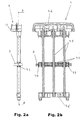
- Figs. 2a, b show again in detail the additional radiator 4 of Fig. 1: First, in Fig. 2a of the Additional radiator 4 with pushed-on separator 5 in Side view shown.
- the radiator 4 has a row of parallel profile tubes 4.1 on, within These electric PTC heating resistors (not shown) for Providing the heating power of the radiator 4 is arranged are.
- the profile tubes 4.1 are at their ends respectively Connection / holding parts 4.2, 4.2 'held and for power the PTC resistors electrically contacted.
- the profile tubes 4.1 To the heat generated by the PTC resistors of the Profile tubes 4.1 to an air flow L1, L2 (Fig. 1) by the heater 1 and the radiator 4 transferred to can, are on the profile tubes 4.1 a number of heat-emitting elements arranged in the form of thin metal fins 4.3, of those in Figs. 2a, b for reasons of clarity only a few are shown explicitly.
- the fins 4.3 are arranged parallel to each other and have suitable breakthroughs, with which they on the Profile tubes 4.1 of the radiator 4 pushed and clamped are held.
- the blades 4.3 according to 2b at their ends curls 4.4, through which they are kept in pairs spaced from each other.
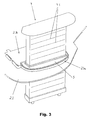
- the separating body 5 has - as already shown in FIGS. 2a, b recognizable and below with reference to FIGS. 3, 4a, 4b yet presented in detail - a key breakthrough, with him on the radiator 4, or more precisely: on the slats 4.3, postponed. This is first in Fig. 3 schematically shown in a perspective view.
- Fig. 3 shows the radiator 4 with on the fins 4.3 deferred separating body 5, in a corresponding Reception 2.3a in the intermediate wall 2.3 (Fig. 1) of the housing 2 of the heater 1 is inserted.
- Some slats 4.3 of the radiator 4 are indicated by way of example.
- Farther is in Fig. 3 in an area behind the radiator 4 a Shooting 2.3b for the heat exchanger 3 of the heater. 1 provided (see Fig. 1).
- the separating body is the fifth the device according to the invention substantially plate-shaped formed, with its outer contour of a Rectangular is borrowed, but in the area of a long side the rectangle at least at the corners a rounded History has.
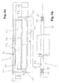
- FIGS. 4a, b A possible inventive design of the separating body 4 is finally shown in detail in FIGS. 4a, b:
- FIG 4a shows a plan view of a separating body 5, essentially the one already shown in FIG Separator corresponds.
- the separating body 5 is its outer Contour after essentially plate-shaped rectangular formed, wherein the longitudinal side 5.1 defining Corners 5.2, 5.2 'formed with a radius R rounded are.
- the separating body 5 has to be pushed onto the with the lamellae 4.3 equipped radiator 4 (see Fig. 3) a central breakthrough 5.3 on, according to the dimensions the fins 4.3 of the radiator 4 rectangular and is formed suitably dimensioned. It corresponds a length 1 and a width b of the aperture 5.3 substantially corresponding dimensions of the slats 4.3.
- Of the Breakthrough 5.3 is in the present case to its entire Extent of the outer contour of several adjacently arranged Slats 4.3 without interposition of seals essentially gastight.
- Inner walls 5.3a, 5.3b of the opening 5.3 has the Separator 5 further projections 5.4, which in deferred Condition of the separator in between spaces engage the slats 4.3 (see Fig. 2b) and so the Separator against displacement in the direction of extension secure the profile tubes 4.1 of the radiator 4.
- the separating body 5 according to the invention is preferably in one flexible, temperature-resistant plastic material is formed, so that for pushing the separator 5 by pulling the long sides 5.1 or 5.3a, 5.3b a clear width of the aperture 5.3 can enlarge to in particular, the projections 5.4 past the blades 4.3 to move until the separator 5 in a desired Position on the fins 4.3 of the radiator 4 is located.
- the separating body has 5 two on its outer contour or on the edge of the Breakthrough 5.3 at least partially parallel to each other Bulges 5.5, 5.5 ', which are described below with reference to Fig. 4b will be explained in more detail.
- FIG. 4 b shows a cross section through the separating body 5 along a line B-B in Fig. 4a.
- the Separator 5 a circumferential, double H-shaped cross-sectional profile on, so in spite of the formation of the separator 5 in flexible plastic material and the provision a central breakthrough 5.3 at a reduced cost of materials a stable configuration of the separator 5 to to reach. Due to the H-shaped profile of the separator 5 exist on its top 5a and bottom 5b the already described above beads 5.5, 5.5 ', which accordingly through the free ends of the parallel legs of the H-shaped Profils are formed.
- the separating body 5 of the device according to the invention at low cost design simple and secure Mount on the fins 4.3 of a radiator 4, wherein its position on the radiator 4 by moving in Extension direction of the profile tubes 4.1 (see Fig. 2b) basically freely selectable.
Applications Claiming Priority (2)
| Application Number | Priority Date | Filing Date | Title |
|---|---|---|---|
| DE202004007039U DE202004007039U1 (de) | 2004-05-03 | 2004-05-03 | Vorrichtung zum Trennen von Fluidströmen in einer Heizeinrichtung |
| DE202004007039U | 2004-05-03 |
Publications (3)
| Publication Number | Publication Date |
|---|---|
| EP1593536A2 true EP1593536A2 (fr) | 2005-11-09 |
| EP1593536A3 EP1593536A3 (fr) | 2006-10-25 |
| EP1593536B1 EP1593536B1 (fr) | 2008-10-29 |
Family
ID=34716835
Family Applications (1)
| Application Number | Title | Priority Date | Filing Date |
|---|---|---|---|
| EP05009297A Expired - Fee Related EP1593536B1 (fr) | 2004-05-03 | 2005-04-28 | Procédé et dispositif pour séparer l'écoulement de fluides dans un dispositif de chauffage |
Country Status (3)
| Country | Link |
|---|---|
| US (1) | US7504606B2 (fr) |
| EP (1) | EP1593536B1 (fr) |
| DE (2) | DE202004007039U1 (fr) |
Families Citing this family (4)
| Publication number | Priority date | Publication date | Assignee | Title |
|---|---|---|---|---|
| JP5122550B2 (ja) * | 2009-11-26 | 2013-01-16 | シャープ株式会社 | Ptcヒータの制御方法及び空気調和機 |
| JP5027863B2 (ja) * | 2009-11-26 | 2012-09-19 | シャープ株式会社 | 空気調和機 |
| US8309894B2 (en) * | 2010-02-12 | 2012-11-13 | General Electric Company | Triac control of positive temperature coefficient (PTC) heaters in room air conditioners |
| DE102012012654A1 (de) * | 2012-06-25 | 2014-01-02 | Valeo Klimasysteme Gmbh | Fahrzeugheizungs-, -lüftungs- und/oder -klimaanlage |
Citations (3)
| Publication number | Priority date | Publication date | Assignee | Title |
|---|---|---|---|---|
| US5057672A (en) | 1988-07-15 | 1991-10-15 | Apparte und Heizwiderstande GmbH | Radiator having ptc electric resistance heating elements and spring-biased fin arrangement |
| EP1061776A1 (fr) | 1999-06-15 | 2000-12-20 | David & Baader DBK Spezialfabrik elektrischer Apparate und Heizwiderstände GmbH | Dispositif de chauffage destiné au réchauffement de l'air |
| EP1507126A2 (fr) | 2003-08-09 | 2005-02-16 | Eichenauer Heizelemente GmbH & Co.KG | Dispositif de chauffage de gaz et ailette pour un tel dispositif |
Family Cites Families (14)
| Publication number | Priority date | Publication date | Assignee | Title |
|---|---|---|---|---|
| US3879599A (en) * | 1974-05-17 | 1975-04-22 | Nobuhisa Kodaira | Heat-treatment apparatus for synthetic fiber yarns |
| US4469582A (en) * | 1982-03-22 | 1984-09-04 | Combustion Engineering, Inc. | Electrically enhanced inclined plate separator |
| DE8236581U1 (de) * | 1982-12-28 | 1983-06-23 | Süddeutsche Kühlerfabrik Julius Fr. Behr GmbH & Co KG, 7000 Stuttgart | Kraftfahrzeug |
| US4576798A (en) * | 1983-06-21 | 1986-03-18 | Safeway Products, Inc. | Contact lens disinfecting unit |
| US5075672A (en) * | 1990-06-27 | 1991-12-24 | Ambartsum S. Pashinian | System for detecting the condition of a lamp and activating a permanent memory two-state display of the lamp condition |
| JP3692572B2 (ja) * | 1995-10-12 | 2005-09-07 | 株式会社デンソー | 空調装置 |
| JP3713780B2 (ja) * | 1995-12-26 | 2005-11-09 | 株式会社デンソー | 空調装置 |
| DE19823061B4 (de) * | 1997-05-23 | 2010-11-11 | DENSO CORPORATION, Kariya-shi | Klimaanlage für ein Fahrzeug |
| DE19755698B4 (de) * | 1997-12-16 | 2006-07-27 | Behr Gmbh & Co. Kg | Heizungs- oder Klimaanlage für ein Kraftfahrzeug |
| US6717115B1 (en) * | 2000-04-25 | 2004-04-06 | Teradyne, Inc. | Semiconductor handler for rapid testing |
| WO2003007407A1 (fr) * | 2001-07-09 | 2003-01-23 | Honda Giken Kogyo Kabushiki Kaisha | Procede de fabrication de separations pour pile a combustible |
| NO316109B1 (no) * | 2001-11-07 | 2003-12-15 | Aibel As | En coalescer anordning |
| DE10250287C1 (de) * | 2002-10-29 | 2003-11-27 | Daimler Chrysler Ag | Wärmetauscher, insbesondere für eine Heiz- und/oder Klimaeinrichtung eines Kraftfahzeuges |
| US6972077B2 (en) * | 2003-05-28 | 2005-12-06 | Tipton Gary A | Cells and electrodes for electrocoagulation treatment of wastewater |
-
2004
- 2004-05-03 DE DE202004007039U patent/DE202004007039U1/de not_active Expired - Lifetime
-
2005
- 2005-04-28 EP EP05009297A patent/EP1593536B1/fr not_active Expired - Fee Related
- 2005-04-28 DE DE502005005775T patent/DE502005005775D1/de active Active
- 2005-05-03 US US11/119,935 patent/US7504606B2/en not_active Expired - Fee Related
Patent Citations (3)
| Publication number | Priority date | Publication date | Assignee | Title |
|---|---|---|---|---|
| US5057672A (en) | 1988-07-15 | 1991-10-15 | Apparte und Heizwiderstande GmbH | Radiator having ptc electric resistance heating elements and spring-biased fin arrangement |
| EP1061776A1 (fr) | 1999-06-15 | 2000-12-20 | David & Baader DBK Spezialfabrik elektrischer Apparate und Heizwiderstände GmbH | Dispositif de chauffage destiné au réchauffement de l'air |
| EP1507126A2 (fr) | 2003-08-09 | 2005-02-16 | Eichenauer Heizelemente GmbH & Co.KG | Dispositif de chauffage de gaz et ailette pour un tel dispositif |
Also Published As
| Publication number | Publication date |
|---|---|
| DE502005005775D1 (de) | 2008-12-11 |
| EP1593536B1 (fr) | 2008-10-29 |
| US20050242082A1 (en) | 2005-11-03 |
| US7504606B2 (en) | 2009-03-17 |
| DE202004007039U1 (de) | 2005-06-30 |
| EP1593536A3 (fr) | 2006-10-25 |
Similar Documents
| Publication | Publication Date | Title |
|---|---|---|
| DE102007028792A1 (de) | Wärmeaustauscher | |
| EP0379873A2 (fr) | Appareil pour chauffeur des gaz | |
| DE102006016711B4 (de) | Flachrohr für Wärmetauscher | |
| DE3142028C2 (fr) | ||
| DE102006002932B4 (de) | Wärmetauscher und Herstellungsverfahren für Wärmetauscher | |
| DE19848169A1 (de) | Vorrichtung zum Beheizen von Innenräumen, insbesondere von Kraftfahrzeugen | |
| DE2306559A1 (de) | Konvektor und herstellungsverfahren | |
| EP1593536B1 (fr) | Procédé et dispositif pour séparer l'écoulement de fluides dans un dispositif de chauffage | |
| DE102005019578A1 (de) | Vorrichtung zum Heizen durch Fluidzirkulation | |
| DE102010033309A1 (de) | Wärmetauscher-Lamellenmodul, Wärmetauscher und elektrisches Heizmodul | |
| DE102007052888A1 (de) | Wärmeübertrager, insbesondere für ein Fahrzeug | |
| EP3786532A1 (fr) | Échangeur de chaleur de surface, système et procédé | |
| DE2530383A1 (de) | Waermeaustauscher, insbesondere kuehler fuer eine kraftfahrzeug-klimaanlage | |
| EP1923654B1 (fr) | Échangeur de chaleur | |
| DE102009041406B3 (de) | Wärmeübertrager | |
| DE102007010530B4 (de) | Behälter für einen Wärmetauscher und Wärmetauscher | |
| DE10143852B4 (de) | Heizkörper | |
| EP1748271B1 (fr) | Tubes et ailettes pour bloc d'échange de chaleur | |
| DE10297468T5 (de) | Lamelle für ein Wärmetauschermodul für insbesondere ein Kraftfahrzeug | |
| EP1923653B1 (fr) | Échangeur de chaleur | |
| DE202017102436U1 (de) | Wärmetauscher mit Mikrokanal-Struktur oder Flügelrohr-Struktur | |
| EP1553363B1 (fr) | Ensemble collecteur pour radiateurs de chauffage ou de réfrigeration | |
| DE2431211A1 (de) | Rippenverteiler, insbesondere fuer elektrische heizelemente | |
| DE19714830C2 (de) | Konvektionsheizung für Großraum-Fahrzeuge | |
| DE202010007533U1 (de) | Wärmetauscher |
Legal Events
| Date | Code | Title | Description |
|---|---|---|---|
| PUAI | Public reference made under article 153(3) epc to a published international application that has entered the european phase |
Free format text: ORIGINAL CODE: 0009012 |
|
| AK | Designated contracting states |
Kind code of ref document: A2 Designated state(s): AT BE BG CH CY CZ DE DK EE ES FI FR GB GR HU IE IS IT LI LT LU MC NL PL PT RO SE SI SK TR |
|
| AX | Request for extension of the european patent |
Extension state: AL BA HR LV MK YU |
|
| PUAL | Search report despatched |
Free format text: ORIGINAL CODE: 0009013 |
|
| AK | Designated contracting states |
Kind code of ref document: A3 Designated state(s): AT BE BG CH CY CZ DE DK EE ES FI FR GB GR HU IE IS IT LI LT LU MC NL PL PT RO SE SI SK TR |
|
| AX | Request for extension of the european patent |
Extension state: AL BA HR LV MK YU |
|
| 17P | Request for examination filed |
Effective date: 20070424 |
|
| AKX | Designation fees paid |
Designated state(s): DE FR |
|
| 17Q | First examination report despatched |
Effective date: 20070827 |
|
| GRAP | Despatch of communication of intention to grant a patent |
Free format text: ORIGINAL CODE: EPIDOSNIGR1 |
|
| GRAS | Grant fee paid |
Free format text: ORIGINAL CODE: EPIDOSNIGR3 |
|
| GRAA | (expected) grant |
Free format text: ORIGINAL CODE: 0009210 |
|
| AK | Designated contracting states |
Kind code of ref document: B1 Designated state(s): DE FR |
|
| REF | Corresponds to: |
Ref document number: 502005005775 Country of ref document: DE Date of ref document: 20081211 Kind code of ref document: P |
|
| PLBE | No opposition filed within time limit |
Free format text: ORIGINAL CODE: 0009261 |
|
| STAA | Information on the status of an ep patent application or granted ep patent |
Free format text: STATUS: NO OPPOSITION FILED WITHIN TIME LIMIT |
|
| 26N | No opposition filed |
Effective date: 20090730 |
|
| REG | Reference to a national code |
Ref country code: FR Ref legal event code: TP |
|
| REG | Reference to a national code |
Ref country code: DE Ref legal event code: R081 Ref document number: 502005005775 Country of ref document: DE Owner name: BORGWARNER LUDWIGSBURG GMBH, DE Free format text: FORMER OWNER: EICHENAUER HEIZELEMENTE GMBH & , BERU AG, , DE Effective date: 20110406 Ref country code: DE Ref legal event code: R081 Ref document number: 502005005775 Country of ref document: DE Owner name: BORGWARNER LUDWIGSBURG GMBH, DE Free format text: FORMER OWNERS: EICHENAUER HEIZELEMENTE GMBH & CO. KG, 76870 KANDEL, DE; BERU AG, 71636 LUDWIGSBURG, DE Effective date: 20110406 |
|
| PGFP | Annual fee paid to national office [announced via postgrant information from national office to epo] |
Ref country code: FR Payment date: 20110427 Year of fee payment: 7 |
|
| REG | Reference to a national code |
Ref country code: FR Ref legal event code: ST Effective date: 20121228 |
|
| PG25 | Lapsed in a contracting state [announced via postgrant information from national office to epo] |
Ref country code: FR Free format text: LAPSE BECAUSE OF NON-PAYMENT OF DUE FEES Effective date: 20120430 |
|
| REG | Reference to a national code |
Ref country code: DE Ref legal event code: R082 Ref document number: 502005005775 Country of ref document: DE Representative=s name: TWELMEIER MOMMER & PARTNER PATENT- UND RECHTSA, DE |
|
| REG | Reference to a national code |
Ref country code: DE Ref legal event code: R081 Ref document number: 502005005775 Country of ref document: DE Owner name: BORGWARNER LUDWIGSBURG GMBH, DE Free format text: FORMER OWNER: BORGWARNER BERU SYSTEMS GMBH, 71636 LUDWIGSBURG, DE Effective date: 20141216 Ref country code: DE Ref legal event code: R082 Ref document number: 502005005775 Country of ref document: DE Representative=s name: TWELMEIER MOMMER & PARTNER PATENT- UND RECHTSA, DE Effective date: 20141216 |
|
| PGFP | Annual fee paid to national office [announced via postgrant information from national office to epo] |
Ref country code: DE Payment date: 20160324 Year of fee payment: 12 |
|
| REG | Reference to a national code |
Ref country code: DE Ref legal event code: R119 Ref document number: 502005005775 Country of ref document: DE |
|
| PG25 | Lapsed in a contracting state [announced via postgrant information from national office to epo] |
Ref country code: DE Free format text: LAPSE BECAUSE OF NON-PAYMENT OF DUE FEES Effective date: 20171103 |