EP1593437B1 - Verfahren und Vorrichtung zum Kaltgasspritzen - Google Patents
Verfahren und Vorrichtung zum Kaltgasspritzen Download PDFInfo
- Publication number
- EP1593437B1 EP1593437B1 EP05009467A EP05009467A EP1593437B1 EP 1593437 B1 EP1593437 B1 EP 1593437B1 EP 05009467 A EP05009467 A EP 05009467A EP 05009467 A EP05009467 A EP 05009467A EP 1593437 B1 EP1593437 B1 EP 1593437B1
- Authority
- EP
- European Patent Office
- Prior art keywords
- particles
- nozzle
- energy
- microwave
- substrate
- Prior art date
- Legal status (The legal status is an assumption and is not a legal conclusion. Google has not performed a legal analysis and makes no representation as to the accuracy of the status listed.)
- Active
Links
Images
Classifications
-
- B—PERFORMING OPERATIONS; TRANSPORTING
- B05—SPRAYING OR ATOMISING IN GENERAL; APPLYING FLUENT MATERIALS TO SURFACES, IN GENERAL
- B05B—SPRAYING APPARATUS; ATOMISING APPARATUS; NOZZLES
- B05B7/00—Spraying apparatus for discharge of liquids or other fluent materials from two or more sources, e.g. of liquid and air, of powder and gas
- B05B7/16—Spraying apparatus for discharge of liquids or other fluent materials from two or more sources, e.g. of liquid and air, of powder and gas incorporating means for heating or cooling the material to be sprayed
-
- B—PERFORMING OPERATIONS; TRANSPORTING
- B05—SPRAYING OR ATOMISING IN GENERAL; APPLYING FLUENT MATERIALS TO SURFACES, IN GENERAL
- B05B—SPRAYING APPARATUS; ATOMISING APPARATUS; NOZZLES
- B05B7/00—Spraying apparatus for discharge of liquids or other fluent materials from two or more sources, e.g. of liquid and air, of powder and gas
- B05B7/14—Spraying apparatus for discharge of liquids or other fluent materials from two or more sources, e.g. of liquid and air, of powder and gas designed for spraying particulate materials
- B05B7/1404—Arrangements for supplying particulate material
-
- B—PERFORMING OPERATIONS; TRANSPORTING
- B05—SPRAYING OR ATOMISING IN GENERAL; APPLYING FLUENT MATERIALS TO SURFACES, IN GENERAL
- B05B—SPRAYING APPARATUS; ATOMISING APPARATUS; NOZZLES
- B05B7/00—Spraying apparatus for discharge of liquids or other fluent materials from two or more sources, e.g. of liquid and air, of powder and gas
- B05B7/14—Spraying apparatus for discharge of liquids or other fluent materials from two or more sources, e.g. of liquid and air, of powder and gas designed for spraying particulate materials
- B05B7/1481—Spray pistols or apparatus for discharging particulate material
- B05B7/1486—Spray pistols or apparatus for discharging particulate material for spraying particulate material in dry state
-
- C—CHEMISTRY; METALLURGY
- C23—COATING METALLIC MATERIAL; COATING MATERIAL WITH METALLIC MATERIAL; CHEMICAL SURFACE TREATMENT; DIFFUSION TREATMENT OF METALLIC MATERIAL; COATING BY VACUUM EVAPORATION, BY SPUTTERING, BY ION IMPLANTATION OR BY CHEMICAL VAPOUR DEPOSITION, IN GENERAL; INHIBITING CORROSION OF METALLIC MATERIAL OR INCRUSTATION IN GENERAL
- C23C—COATING METALLIC MATERIAL; COATING MATERIAL WITH METALLIC MATERIAL; SURFACE TREATMENT OF METALLIC MATERIAL BY DIFFUSION INTO THE SURFACE, BY CHEMICAL CONVERSION OR SUBSTITUTION; COATING BY VACUUM EVAPORATION, BY SPUTTERING, BY ION IMPLANTATION OR BY CHEMICAL VAPOUR DEPOSITION, IN GENERAL
- C23C24/00—Coating starting from inorganic powder
- C23C24/02—Coating starting from inorganic powder by application of pressure only
- C23C24/04—Impact or kinetic deposition of particles
Definitions
- the invention relates to a method for cold gas spraying, wherein particles are accelerated in a gas jet and the particles impinge on a workpiece at high speed, and wherein the gas jet is accelerated by relaxation in a nozzle and thereby cools. Furthermore, the invention relates to a device for cold gas spraying comprising a nozzle which is divided into a convergent nozzle section and a nozzle outlet.
- a gas in a de Laval nozzle is accelerated to supersonic speed.
- the coating material is injected as a powder before or after the nozzle throat into the gas jet and accelerated toward the substrate.
- the high-speed particles form a dense and firmly adhering layer upon impact. For this, the particles must deform.
- Heating the gas jet increases the flow velocity of the gas and thus also the particle velocity.
- the associated heating of the particles also promotes deformation upon impact.
- the gas temperature is well below the melting temperature of the coating material, so that melting of the particles in the gas jet can not take place.
- cold gas spraying eliminates the disadvantages associated with melting, such as oxidation and other phase changes.
- the method of cold gas spraying includes, for example, EP 484 533. Recently, it has been found that dense and adherent layers are not only formed when the gas in a Laval nozzle accelerates to supersonic speed but also when the gas accelerates only at speeds close to the speed of sound becomes.
- a method with acceleration to speeds close to the speed of sound includes, for example, DE 101 19 288.
- a Laval nozzle is divided into a convergent section, which ends in the nozzle throat, and into a divergent section beginning at the nozzle throat.
- a nozzle in which gas is accelerated to near the speed of sound, is divided into a convergent section, which ends in the nozzle throat and a nozzle neck on the subsequent section which is conical or cylindrical.
- An advantage for the layer is when the particles are warm (but not fused) upon impact with the substrate, as this aids in plastic deformation. Melting of the particles can change the properties of the coating to their disadvantage. Practice has shown that the particles in the hot gas jet heat well and reach temperatures near the gas temperature. In the second section of the nozzle, the nozzle outlet, as well as in the spray free jet between the nozzle outlet and the substrate, the particles cool down again very quickly. Thus, heat is missing on impact, which favors the plastic deformability. This can adversely affect the layer properties.
- the cooling is due to the fact that the gas acceleration takes place in the nozzle outlet and the gas acceleration is accompanied by a cooling of the gas. For some nozzle geometries, the gas temperature at the nozzle exit is far below freezing. Since the particles interact very well with the gas jet, the temperature of the particles also drops sharply.
- the invention has for its object to provide a method and an apparatus that allow a relatively high temperature of the particles upon impact with the substrate.
- the object is achieved for the method according to the invention that energy is supplied to the particles via microwave technology.
- the energy supplied with the aid of microwave technology heats the particles. Warmer particles deform better than colder particles when they hit the workpiece, because in addition to the kinetic energy, the thermal energy of the particles is also available for layer formation. This improves the quality of the coating in terms of layer properties and adhesion to the substrate. Increasing the available energy leads to an improvement in the adhesion of the particles on the ground and the particles with each other.
- the loss of heat which the particles experience as a result of the gas temperature sinking during the acceleration of the gas jet is at least partially compensated.
- the heat loss is not only absorbed by the energy input via the microwave technology, but the particles are heated above the outlet temperature in front of the nozzle throat. Since the heat promotes plastic deformability, the more the particles are heated, the easier it is for the particles to deform on impact. As long as the temperature of the heated particles is below the melting point of the particles, a coating or molding is formed which is typical in its properties for cold gas spraying. If temperatures above the melting point of the particles are reached during heating, the particles are fused or melted. Melting of the particles alters the properties of the coating, particularly with respect to the stress ratios in the coating. However, in various cases, coatings formed from on or through molten particles may also be advantageous.
- the particles are supplied with the energy in the nozzle.
- the loss of heat which the particles in the nozzle undergo as a result of the cooling of the gas jet is partially compensated there, completely compensated or overcompensated, where the cooling of the particles occurs due to the acceleration of the gas in the nozzle and the associated cooling is.
- the temperature of the particles therefore drops only slightly and extreme fluctuations are avoided.
- the particles are supplied with the energy after they have left the nozzle.
- the particles are supplied with energy in the nozzle and after leaving the nozzle.
- the time available for heating is particularly long. This is advantageous if the particles are to be heated very strongly or can be heated very badly or if the microwave technology provides only a small power.
- the particles are supplied with energy only after leaving the nozzle. The advantage here is that the microwave waveguide does not have to surround the nozzle and is not affected in its properties of the nozzle.
- metallic particles or non-metallic particles which absorb microwaves are used. If the particles absorb the microwave radiation, the particles are heated by a direct interaction with the microwaves.
- Metallic particles absorb microwaves and are suitable as Coating material.
- microwave-absorbing particles in particular silicon carbides and zirconium oxides are suitable as coating material.
- the particles strike the substrate at a temperature of from 10 to 800.degree. C., preferably from 20 to 500.degree. C., more preferably from 100 to 400.degree. If the temperature of the spray particles is between approximately room temperature and the given values in the range of a few hundred degrees Celsius, the particles are well heated, so that they deform slightly on impact, but are generally not melted, so that coatings typical for cold gas spraying arise.
- the energy is supplied at a frequency of 915 MHz, 2.45 GHz and / or 5.8 GHz.
- Microwave radiation of these ISM frequencies are particularly easy to handle and are suitable for heating the particles.
- the nozzle is at least partially surrounded by a microwave waveguide (6) and / or a / the microwave waveguide (6) at least partially surrounds the spray free jet between the nozzle outlet (3) and substrate.
- the nozzle is thus at least partially surrounded by a microwave waveguide and / or to the nozzle outlet closes either directly or at a distance / the microwave waveguide.
- At least a portion of the nozzle outlet made of a ceramic, preferably made of alumina.
- the microwave waveguide advantageously surrounds at least the ceramic section of the nozzle outlet.
- the microwaves penetrate the ceramic section with particularly low losses and are absorbed by the particles in the nozzle interior, whereby the particles heat up.
- the nozzle outlet is designed diverging or cylindrical or conically tapered. Such nozzle geometries are particularly suitable for cold gas spraying.
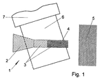
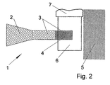
- Figures 1 and 2 include a nozzle 1 with a convergent nozzle portion 2 and a nozzle outlet 3 and a ceramic portion 4 and a substrate 5 and a microwave waveguide 6 with a terminal 7 to a microwave source.
- the nozzle 1 is divided into the convergent nozzle section 2, which merges into the nozzle outlet 3 at the nozzle neck.
- the nozzle is inserted into the microwave waveguide 6.
- the microwave waveguide 6 is connected via a connection 7 to the microwave source.
- the metallic material from which nozzles are normally made replaced by a ceramic.
- the metallic material of the nozzle outlet 4 now penetrate the microwaves of the microwave waveguide 6 in the nozzle, while the metallic material of the nozzle shields the microwaves.
- the microwaves are absorbed by the particles and the particles heat up. The heated particles strike the substrate 5 and form the coating there.
- the metallic material is replaced by a ceramic only in a small area at the end of the nozzle outlet 3.
- This ceramic section 4 approximately and almost the entire path that the particles travel between the nozzle exit and the substrate 5 as a spray-free jet, is covered by the Microwave waveguide 6 surrounded. The particles are thus heated on the last piece in the nozzle and after the nozzle exit until just before the substrate 5.
- a microwave waveguide is advantageously used, which is designed as a rectangular microwave waveguide.
- Microwave waveguides are used to transmit microwaves over short distances. Particles that move in the microwave waveguide absorb the microwaves and heat up.
- the rectangular microwave waveguide forms a standing wave, which is particularly suitable for energy transmission.
- this is operated with ISM frequencies.
Landscapes
- Chemical & Material Sciences (AREA)
- Chemical Kinetics & Catalysis (AREA)
- Engineering & Computer Science (AREA)
- Materials Engineering (AREA)
- Mechanical Engineering (AREA)
- Metallurgy (AREA)
- Organic Chemistry (AREA)
- Nozzles (AREA)
- Physical Or Chemical Processes And Apparatus (AREA)
Description
- Die Erfindung betrifft ein Verfahren zum Kaltgasspritzen, wobei Partikel in einem Gasstrahl beschleunigt werden und die Partikel mit hoher Geschwindigkeit auf ein Werkstück auftreffen, und wobei der Gasstrahl durch Entspannung in einer Düse beschleunigt wird und sich dabei abkühlt. Ferner betrifft die Erfindung eine Vorrichtung zum Kaltgasspritzen umfassend eine Düse, die sich in einen konvergent zulaufenden Düsenabschnitt und einen Düsenauslauf gliedert.
- Beim Kaltgasspritzen wird ein Gas in einer de Lavaldüse auf Überschallgeschwindigkeit beschleunigt. Der Beschichtungswerkstoff wird als Pulver vor oder nach dem Düsenhals in den Gasstrahl injiziert und auf das Substrat hin beschleunigt. Die auf hohe Geschwindigkeit gebrachten Partikel bilden beim Aufprall eine dichte und fest haftende Schicht. Dazu müssen sich die Partikel verformen. Ein Aufheizen des Gasstrahls erhöht die Strömungsgeschwindigkeit des Gases und somit auch die Partikelgeschwindigkeit. Die damit ebenfalls verbundene Erwärmung der Partikel begünstigt das Verformen beim Aufprall. Die Gastemperatur liegt aber deutlich unterhalb der Schmelztemperatur des Beschichtungswerkstoffs, so dass ein Schmelzen der Partikel im Gasstrahl nicht stattfinden kann. Im Vergleich zu den Verfahren des thermischen Spritzens lassen sich beim Kaltgasspritzen die mit dem Schmelzen verbundenen Nachteile wie Oxidation und andere Phasenumwandlungen vermeiden.
- Das Verfahren des Kaltgasspritzens beinhaltet beispielsweise die EP 484 533. In jüngster Zeit hat sich gezeigt, dass dichte und fest haftende Schichten nicht nur dann entstehen, wenn das Gas in einer Lavaldüse auf Überschallgeschwindigkeit sondern auch wenn das Gas nur auf Geschwindigkeiten nahe an der Schallgeschwindigkeit beschleunigt wird. Ein Verfahren mit Beschleunigung auf Geschwindigkeiten nahe der Schallgeschwindigkeit beinhaltet beispielsweise die DE 101 19 288. Eine Lavaldüse gliedert sich in einen konvergenten Abschnitt, der im Düsenhals endet, und in einen am Düsenhals beginnenden divergenten Abschnitt. Eine Düse, in der Gas auf nahezu Schallgeschwindigkeit beschleunigt wird, gliedert sich in einen konvergenten Abschnitt, der im Düsenhals endet und einen sich am Düsenhals anschließenden Abschnitt, der konisch oder zylindrisch gestaltet ist.
- Von Vorteil für die Schicht ist, wenn die Partikel beim Aufprall auf das Substrat warm (aber nicht angeschmolzen) sind, da dies die plastische Verformung unterstützt. Ein Anschmelzen der Partikel kann die Eigenschaften der Beschichtung zu ihren Ungunsten verändern. Die Praxis hat gezeigt, dass sich die Partikel in dem heißen Gasstrahl gut erwärmen und Temperaturen nahe der Gastemperatur erreichen. In dem zweiten Abschnitt der Düse, dem Düsenauslauf, sowie im Spritzfreistrahl zwischen Düsenaustritt und Substrat kühlen die Partikel sehr schnell wieder ab. Damit fehlt beim Aufprall Wärme, welche die plastische Verformbarkeit begünstigt. Dies kann sich nachteilig auf die Schichteigenschaften auswirken. Die Abkühlung ist darauf zurückzuführen, dass im Düsenauslauf die Gasbeschleunigung stattfindet und die Gasbeschleunigung mit einer Abkühlung des Gases einhergeht. Bei manchen Düsengeometrien liegt die Gastemperatur am Düsenaustritt weit unter dem Gefrierpunkt. Da die Partikel mit dem Gasstrahl sehr gut wechselwirken, sinkt auch die Temperatur der Partikel stark ab.
- Der Erfindung liegt die Aufgabe zugrunde, ein Verfahren und eine Vorrichtung anzugeben, die eine vergleichsweise hohe Temperatur der Partikel beim Aufprall auf das Substrat ermöglichen.
- Die Aufgabe wird für das Verfahren erfindungsgemäß dadurch gelöst, dass den Partikeln über Mikrowellentechnik Energie zugeführt wird. Durch die mit Hilfe der Mikrowellentechnik zugeführte Energie werden die Partikel erwärmt. Wärmere Partikel verformen sich beim Auftreffen auf das Werkstück besser als kältere Partikel, da neben der kinetischen Energie auch die thermische Energie der Partikel zur Schichtausbildung zur Verfügung steht. Dies verbessert die Qualität der Beschichtung in Bezug auf Schichteigenschaften und Haftung auf dem Untergrund. Die Erhöhung der zur Verfügung stehenden Energie führt zu einer Verbesserung der Haftung der Partikel auf dem Untergrund und der Partikel untereinander. Mit dem erfindungsgemäßen Verfahren wird der Verlust an Wärme, den die Partikel aufgrund des bei der Beschleunigung des Gasstrahls erfolgenden Sinkens der Gastemperatur erfahren, zumindest zu einem Teil kompensiert. Bevorzugt wird der Wärmeverlust durch den Energieeintrag über die Mikrowellentechnik nicht nur aufgefangen, sondern die Partikel werden über die vor dem Düsenhals vorliegende Ausgangstemperatur hinaus erwärmt. Da die Wärme die plastische Verformbarkeit begünstigt, gilt: je stärker die Partikel erwärmt werden, desto leichter lassen sich die Partikel beim Aufprall verformen. Solange die Temperatur der erwärmten Partikel unter dem Schmelzpunkt der Partikel liegt, bildet sich eine Beschichtung oder ein Formteil aus, die in ihren Eigenschaften für das Kaltgasspritzen typisch ist. Werden bei der Erwärmung Temperaturen über dem Schmelzpunkt der Partikel erreicht, werden die Partikel an- oder aufgeschmolzen. Ein Schmelzen der Partikel ändert die Eigenschaften der Beschichtung, insbesondere in Bezug auf die Spannungsverhältnisse in der Beschichtung. Jedoch können in verschiedenen Fällen auch Beschichtungen, die aus an- oder durchgeschmolzenen Partikel gebildet werden, von Vorteil sein.
- Mit besonderem Vorteil wird den Partikeln die Energie in der Düse zugeführt. Der Verlust an Wärme, welchen die Partikel in der Düse durch die Abkühlung des Gasstrahls erfahren, wird dort teilweise kompensiert, vollständig kompensiert oder überkompensiert, wo die Abkühlung der Partikel erfolgt, die auf die Beschleunigung des Gases in der Düse und der damit verbundenen Abkühlung zurückzuführen ist. Die Temperatur der Partikel sinkt deshalb nur wenig ab und extreme Schwankungen werden vermieden.
- Vorteilhafterweise wird den Partikeln die Energie zugeführt, nachdem sie die Düse verlassen haben. Hierzu gibt es zwei mögliche Ausgestaltungen: Bei der ersten wird den Partikeln Energie in der Düse und nach dem Verlassen der Düse zugeführt. In diesem Fall ist die Zeitspanne, die zur Erwärmung zur Verfügung steht besonders lang. Von Vorteil ist dies, wenn die Partikel sehr stark erwärmt werden sollen beziehungsweise sich sehr schlecht erwärmen lassen oder wenn die Mikrowellentechnik nur eine geringe Leistung liefert. Bei der zweiten Ausgestaltung wird den Partikeln nur nach dem Verlassen der Düse Energie zugeführt. Von Vorteil ist hierbei, dass der Mikrowellenhohlleiter nicht die Düse umgeben muss und auch nicht in seinen Eigenschaften von der Düse beeinflusst wird.
- In vorteilhafter Ausgestaltung werden metallische Partikel oder nichtmetallische Partikel, die Mikrowellen absorbieren, verwendet. Absorbieren die Partikel die Mikrowellenstrahlung, werden die Partikel durch eine direkte Wechselwirkung mit den Mikrowellen erwärmt. Metallische Partikel absorbieren Mikrowellen und eignen sich als Beschichtungsmaterial. Von den nichtmetallischen, Mikrowellen absorbierenden Partikeln eignen sich insbesondere Siliziumkarbide und Zirkonoxide als Beschichtungsmaterial.
- Vorteilhafterweise treffen die Partikel mit einer Temperatur von 10 bis 800 °C, vorzugsweise von 20 bis 500 °C, besonders bevorzugt von 100 bis 400 °C auf das Substrat. Liegt die Temperatur der Spritzpartikel zwischen in etwa Raumtemperatur und den angegeben Werten im Bereich von einigen hundert Grad Celsius sind die Partikel gut erwärmt, so dass sie sich bei Aufprall leicht verformen, aber in der Regel noch nicht aufgeschmolzen, so dass für das Kaltgasspritzen typische Beschichtungen entstehen.
- Mit besonderem Vorteil wird die Energie mit einer Frequenz von 915 MHz, 2,45 GHz oder/und 5,8 GHz zugeführt. Mikrowellenstrahlung dieser ISM-Frequenzen sind besonders gut handhabbar und eignen sich zur Erwärmung der Partikel.
- Die Aufgabe wird für die Vorrichtung erfindungsgemäß dadurch gelöst, dass die Düse zumindest teilweise von einem Mikrowellenhohlleiter (6) umgeben ist oder/und ein/der Mikrowellenhohlleiter (6) zumindest teilweise den Spritzfreistrahl zwischen Düsenaustritt (3) und Substrat umschließt. Erfindungsgemäß ist die Düse somit zumindest teilweise von einem Mikrowellenhohlleiter umgeben oder/und an den Düsenauslauf schließt sich entweder direkt oder mit Abstand ein/der Mikrowellenhohlleiter an. Die erfindungsgemäße Vorrichtung weist somit die vorgenannten Vorteile aus.
- In vorteilhafter Ausgestaltung ist zumindest ein Abschnitt des Düsenauslaufs aus einer Keramik, vorzugsweise aus Aluminiumoxid, gefertigt.
- Weiterhin umgibt der Mikrowellenhohlleiter vorteilhafterweise zumindest den keramischen Abschnitt des Düsenauslaufs. Die Mikrowellen durchdringen den keramischen Abschnitt besonders verlustarm und werden von den Partikeln im Düseninnem absorbiert, wobei sich die Partikeln erwärmen.
- In vorteilhafter Ausgestaltung ist der Düsenauslauf divergierend oder zylindrisch oder konisch zulaufend gestaltet. Derartige Düsengeometrien eignen sich in besonderer Weise zum Kaltgasspritzen.
- Im Folgenden wird die Erfindung in zwei beispielhaften Ausgestaltungen mit Hilfe von Figuren näher erläutert. Hierzu zeigt
- Figur 1
- eine beispielhafte Ausgestaltung, in welcher die Düse zu einem großen Teil von einem Mikrowellenhohlleiter umgeben ist, und
- Figur 2
- eine beispielhafte Ausgestaltung, in welcher ein Teil des Düseauslaufs und der Weg der Partikel von der Düse bis in die Nähe des Substrats von einem Mikrowellenhohlleiter umgeben ist.
- Figur 1 und 2 beinhalten eine Düse 1 mit einem konvergenten Düsenabschnitt 2 und einem Düsenauslauf 3 und einem keramischen Abschnitt 4 sowie ein Substrat 5 und einen Mikrowellenhohlleiter 6 mit einem Anschluss 7 an eine Mikrowellenquelle.
- In der beispielhaften Ausgestaltung gemäß Figur 1 gliedert sich die Düse 1 in den konvergenten Düsenabschnitt 2, der am Düsenhals in den Düsenauslauf 3 übergeht. Die Düse ist in den Mikrowellenhohlleiter 6 eingeführt. Der Mikrowellenhohlleiter 6 ist über einen Anschluss 7 an die Mikrowellenquelle angeschlossen. Bei einem Teil der Düse, der hier den Großteil des Düsenauslaufs 3 umfasst und bis zum Düsenende reicht, ist der metallische Werkstoff, aus welchem Düsen normalerweise gefertigt werden, durch eine Keramik ersetzt. In diesen keramischen Abschnitt des Düsenauslaufs 4 dringen nun die Mikrowellen des Mikrowellenhohlleiters 6 in die Düse ein, während der metallische Werkstoff der Düse die Mikrowellen abschirmt. Im Inneren der Düse werden die Mikrowellen von den Partikeln absorbiert und die Partikel erwärmen sich. Die erwärmten Partikel treffen auf das Substrat 5 und bilden dort die Beschichtung aus.
- In der beispielhaften Ausgestaltung gemäß Figur 2 ist der metallische Werkstoff nur in einem kleinen Bereich am Ende des Düsenauslaufs 3 durch eine Keramik ersetzt. Dieser keramische Abschnitt 4 in etwa und nahezu der gesamte Weg, den die Partikel zwischen Düsenaustritt und Substrat 5 als Spritzfreistrahl zurücklegen, wird von dem Mikrowellenhohlleiter 6 umgeben. Die Partikel werden somit auf dem letzten Stück in der Düse und nach dem Düsenaustritt bis kurz vor das Substrat 5 erwärmt.
- Bei diesen beispielhaften Ausgestaltungen wird mit Vorteil ein Mikrowellenhohlleiter verwendet, der als Rechteckmikrowellenhohlleiter ausgestaltet ist. Mikrowellenhohlleiter werden eingesetzt, um Mikrowellen über kurze Distanzen zu übertragen. Partikel, die sich im Mikrowellenhohlleiter bewegen absorbieren die Mikrowellen und erwärmen sich dadurch. Im Rechteckmikrowellenhohlleiter bildet sich eine Stehwelle aus, welche sich besonders gut zur Energieübertragung eignet. Vorteilhafterweise wird dieser mit ISM-Frequenzen betrieben.
-
- 1
- Düse
- 2
- konvergenter Düsenabschnitt
- 3
- Düsenauslauf
- 4
- keramischer Abschnitt des Düsenauslaufs
- 5
- Substrat
- 6
- Mikrowellenhohlleiter
- 7
- Anschluss des Mikrowellenhohlleiter an die Mikrowellenquelle
Claims (10)
- Verfahren zum Kaltgasspritzen, wobei Partikel in einem Gasstrahl beschleunigt werden und die Partikel mit hoher Geschwindigkeit auf ein Substrat (5) auftreffen, und wobei der Gasstrahl durch Entspannung in einer Düse (1) beschleunigt wird und sich dabei abkühlt, dadurch gekennzeichnet, dass den Partikeln über Mikrowellentechnik (6, 7) Energie zugeführt wird.
- Verfahren nach Anspruch 1, dadurch gekennzeichnet, dass den Partikeln die Energie in der Düse zugeführt wird.
- Verfahren nach Anspruch 1 dadurch gekennzeichnet, dass den Partikeln die Energie zugeführt wird, nachdem sie die Düse verlassen haben.
- Verfahren nach einem der Ansprüche 1 bis 3, dadurch gekennzeichnet, dass metallische Partikel oder nichtmetallische Partikel, die Mikrowellen absorbieren, verwendet werden.
- Verfahren nach einem der Ansprüche 1 bis 4, dadurch gekennzeichnet, dass die Partikel mit einer Temperatur von 10 bis 800 °C, vorzugsweise von 20 bis 500 °C, besonders bevorzugt von 100 bis 400 °C auf das Substrat auftreffen.
- Verfahren nach einem der Ansprüche 1 bis 5, dadurch gekennzeichnet, dass die Energie mit einer Frequenz von 915 MHz, 2,45 GHz oder/und 5,8 GHz zugeführt wird.
- Vorrichtung zum Kaltgasspritzen umfassend eine Düse (1), die sich in einen konvergent zulaufenden Düsenabschnitt (2) und einen Düsenauslauf (3) gliedert, dadurch gekennzeichnet, dass die Düse zumindest teilweise von einem Mikrowetlenhohlleiter (6) umgeben ist oder/und ein/der Mikrowellenhohlleiter (6) zumindest teilweise den Spritzfreistrahl zwischen Düsenaustritt (3) und Substrat (5) umschließt.
- Vorrichtung nach Anspruch 7, dadurch gekennzeichnet, dass zumindest ein Abschnitt des Düsenauslaufs aus einer Keramik (4), vorzugsweise aus Aluminiumoxid, gefertigt ist
- Vorrichtung nach Anspruch 7 oder 8, dadurch gekennzeichnet, dass der Mikrowellenhohlleiter (6) zumindest den keramischen Abschnitt (4) des Düsenauslaufs (3) umgibt.
- Vorrichtung nach einem Ansprüche 7 bis 9, dadurch gekennzeichnet, dass der Düsenauslauf (3) divergierend oder zylindrisch oder konisch zulaufend gestaltet ist.
Applications Claiming Priority (4)
| Application Number | Priority Date | Filing Date | Title |
|---|---|---|---|
| DE102004021846 | 2004-05-04 | ||
| DE102004021846 | 2004-05-04 | ||
| DE102004029354 | 2004-06-17 | ||
| DE102004029354A DE102004029354A1 (de) | 2004-05-04 | 2004-06-17 | Verfahren und Vorrichtung zum Kaltgasspritzen |
Publications (2)
| Publication Number | Publication Date |
|---|---|
| EP1593437A1 EP1593437A1 (de) | 2005-11-09 |
| EP1593437B1 true EP1593437B1 (de) | 2006-10-25 |
Family
ID=34935968
Family Applications (1)
| Application Number | Title | Priority Date | Filing Date |
|---|---|---|---|
| EP05009467A Active EP1593437B1 (de) | 2004-05-04 | 2005-04-29 | Verfahren und Vorrichtung zum Kaltgasspritzen |
Country Status (4)
| Country | Link |
|---|---|
| US (1) | US20060027687A1 (de) |
| EP (1) | EP1593437B1 (de) |
| AT (1) | ATE343431T1 (de) |
| DE (2) | DE102004029354A1 (de) |
Cited By (4)
| Publication number | Priority date | Publication date | Assignee | Title |
|---|---|---|---|---|
| DE102012000816A1 (de) | 2012-01-17 | 2013-07-18 | Linde Aktiengesellschaft | Verfahren und Vorrichtung zum thermischen Spritzen |
| US11662300B2 (en) | 2019-09-19 | 2023-05-30 | Westinghouse Electric Company Llc | Apparatus for performing in-situ adhesion test of cold spray deposits and method of employing |
| US11898986B2 (en) | 2012-10-10 | 2024-02-13 | Westinghouse Electric Company Llc | Systems and methods for steam generator tube analysis for detection of tube degradation |
| US11935662B2 (en) | 2019-07-02 | 2024-03-19 | Westinghouse Electric Company Llc | Elongate SiC fuel elements |
Families Citing this family (15)
| Publication number | Priority date | Publication date | Assignee | Title |
|---|---|---|---|---|
| BRPI0611539B1 (pt) * | 2005-05-05 | 2017-04-04 | Starck H C Gmbh | método de aplicar um revestimento a uma superfície, camada de aspersão a frio e objeto revestido |
| CA2664929C (en) * | 2006-09-29 | 2014-07-08 | Siemens Aktiengesellschaft | Method and device for depositing a nonmetallic coating by means of cold gas spraying |
| US20080078268A1 (en) | 2006-10-03 | 2008-04-03 | H.C. Starck Inc. | Process for preparing metal powders having low oxygen content, powders so-produced and uses thereof |
| RU2469126C2 (ru) * | 2006-11-07 | 2012-12-10 | Х.К. Штарк Гмбх | Способ нанесения покрытия на поверхность субстрата и продукт с покрытием |
| US20080145688A1 (en) | 2006-12-13 | 2008-06-19 | H.C. Starck Inc. | Method of joining tantalum clade steel structures |
| DE102007009600A1 (de) | 2007-02-26 | 2008-08-28 | Linde Ag | Verfahren zum Substratbeschichten durch thermisches oder kinetisches Spritzen |
| US8197894B2 (en) | 2007-05-04 | 2012-06-12 | H.C. Starck Gmbh | Methods of forming sputtering targets |
| DE102007023444B4 (de) * | 2007-05-16 | 2009-04-09 | Xtreme Technologies Gmbh | Einrichtung zur Erzeugung eines Gasvorhangs für plasmabasierte EUV-Strahlungsquellen |
| JP5171125B2 (ja) * | 2007-06-25 | 2013-03-27 | プラズマ技研工業株式会社 | コールドスプレー用のノズル及びそのコールドスプレー用のノズルを用いたコールドスプレー装置 |
| US8246903B2 (en) | 2008-09-09 | 2012-08-21 | H.C. Starck Inc. | Dynamic dehydriding of refractory metal powders |
| US8192799B2 (en) * | 2008-12-03 | 2012-06-05 | Asb Industries, Inc. | Spray nozzle assembly for gas dynamic cold spray and method of coating a substrate with a high temperature coating |
| US20120010645A1 (en) * | 2009-03-20 | 2012-01-12 | Proarc Medical Ltd. | Methods and devices for urethral treatment |
| US8734896B2 (en) | 2011-09-29 | 2014-05-27 | H.C. Starck Inc. | Methods of manufacturing high-strength large-area sputtering targets |
| DE102016217367A1 (de) | 2016-09-13 | 2018-03-15 | Robert Bosch Gmbh | Verfahren zur Herstellung eines Aktivmaterials für eine Elektrode einer Batteriezelle, Anordnung zur Herstellung eines Aktivmaterials für eine Elektrode einer Batteriezelle und Batteriezelle |
| DE102018209937A1 (de) | 2018-06-20 | 2019-12-24 | Robert Bosch Gmbh | Verfahren zur Herstellung eines Polymerverbundwerkstoffs für eine elektrochemische Zelle mittels eines gequollenen Polymers |
Family Cites Families (3)
| Publication number | Priority date | Publication date | Assignee | Title |
|---|---|---|---|---|
| EP0484533B1 (de) * | 1990-05-19 | 1995-01-25 | Anatoly Nikiforovich Papyrin | Beschichtungsverfahren und -vorrichtung |
| DE10119288B4 (de) * | 2001-04-20 | 2006-01-19 | Koppenwallner, Georg, Dr.-Ing.habil. | Verfahren und Einrichtung zur gasdynamischen Beschichtung von Oberflächen mittels Schalldüsen |
| DE10207525A1 (de) * | 2002-02-22 | 2003-09-04 | Linde Ag | Verfahren und Vorrichtung zum Kaltgasspritzen |
-
2004
- 2004-06-17 DE DE102004029354A patent/DE102004029354A1/de not_active Withdrawn
-
2005
- 2005-04-29 AT AT05009467T patent/ATE343431T1/de not_active IP Right Cessation
- 2005-04-29 EP EP05009467A patent/EP1593437B1/de active Active
- 2005-04-29 DE DE502005000149T patent/DE502005000149D1/de not_active Expired - Fee Related
- 2005-05-03 US US11/119,724 patent/US20060027687A1/en not_active Abandoned
Cited By (5)
| Publication number | Priority date | Publication date | Assignee | Title |
|---|---|---|---|---|
| DE102012000816A1 (de) | 2012-01-17 | 2013-07-18 | Linde Aktiengesellschaft | Verfahren und Vorrichtung zum thermischen Spritzen |
| EP2617868A1 (de) | 2012-01-17 | 2013-07-24 | Linde Aktiengesellschaft | Verfahren und Vorrichtung zum thermischen Spritzen |
| US11898986B2 (en) | 2012-10-10 | 2024-02-13 | Westinghouse Electric Company Llc | Systems and methods for steam generator tube analysis for detection of tube degradation |
| US11935662B2 (en) | 2019-07-02 | 2024-03-19 | Westinghouse Electric Company Llc | Elongate SiC fuel elements |
| US11662300B2 (en) | 2019-09-19 | 2023-05-30 | Westinghouse Electric Company Llc | Apparatus for performing in-situ adhesion test of cold spray deposits and method of employing |
Also Published As
| Publication number | Publication date |
|---|---|
| US20060027687A1 (en) | 2006-02-09 |
| DE102004029354A1 (de) | 2005-12-01 |
| ATE343431T1 (de) | 2006-11-15 |
| EP1593437A1 (de) | 2005-11-09 |
| DE502005000149D1 (de) | 2006-12-07 |
Similar Documents
| Publication | Publication Date | Title |
|---|---|---|
| EP1593437B1 (de) | Verfahren und Vorrichtung zum Kaltgasspritzen | |
| EP1999297B1 (de) | Kaltgasspritzpistole | |
| EP1390152B1 (de) | Verfahren und vorrichtung zum kaltgasspritzen | |
| DE102013022096B4 (de) | Vorrichtung und Verfahren zum tiegelfreien Schmelzen eines Materials und zum Zerstäuben des geschmolzenen Materials zum Herstellen von Pulver | |
| EP1888803B1 (de) | Verfahren zum gasdynamischen aufbringen von beschichtungen und beschichtungsverfahren | |
| EP2108051B1 (de) | Verfahren und vorrichtung zum kaltgasspritzen von partikeln unterschiedlicher festigkeit und/oder duktilität | |
| EP1791645A1 (de) | Verfahren zum kaltgasspritzen und kaltgasspritzpistole mit erhöhter verweildauer des pulvers im gasstrahl | |
| EP1785679A1 (de) | Vorrichtung zur Hochdruckgaserhitzung | |
| EP2260119B1 (de) | Kaltgasspritzanlage | |
| DE102009005528A1 (de) | Zweistoffdüse | |
| DE102006044612A1 (de) | Verfahren zum Kaltgasspritzen | |
| EP2872258B1 (de) | Kaltgasspritzpistole mit pulverinjektor | |
| WO2006034777A1 (de) | Verfahren und vorrichtung zum kaltgasspritzen mit mehrfacher gasheizung | |
| EP1854547A1 (de) | Kaltgasspritzpistole | |
| DE112016005061T5 (de) | Vorrichtung und Verfahren für Kalt-Sprüh- und Beschichtungs-Verarbeitung | |
| EP1506816B1 (de) | Lavaldüse für thermisches oder kinetisches Spritzen | |
| EP2617868B1 (de) | Verfahren und Vorrichtung zum thermischen Spritzen | |
| DE10119288B4 (de) | Verfahren und Einrichtung zur gasdynamischen Beschichtung von Oberflächen mittels Schalldüsen | |
| EP2503026A1 (de) | Verfahren zum Reparieren einer Schicht auf einem Substrat | |
| DE102009052970A1 (de) | Kaltgasspritzdüse und Kaltgasspritzvorrichtung mit einer derartigen Spritzdüse | |
| DE10207519A1 (de) | Vorrichtung zum Kaltgasspritzen | |
| DE102004022358B3 (de) | Hartstoffbeschichtungsverfahren und dessen Verwendung | |
| EP3842208B1 (de) | Verwendung einer vorrichtung zur induktiven erwärmung eines elektrisch-leitenden, vorzugsweise metallischen, einlegeteils als bestandteil eines spritzgiesslings | |
| EP3219987A1 (de) | Entladungskammer für ein ionentriebwerk | |
| DE102019218273A1 (de) | Kaltgas-Spritzanlage mit einer Heizgasdüse und Verfahren zum Beschichten eines Substrats |
Legal Events
| Date | Code | Title | Description |
|---|---|---|---|
| PUAI | Public reference made under article 153(3) epc to a published international application that has entered the european phase |
Free format text: ORIGINAL CODE: 0009012 |
|
| AK | Designated contracting states |
Kind code of ref document: A1 Designated state(s): AT BE BG CH CY CZ DE DK EE ES FI FR GB GR HU IE IS IT LI LT LU MC NL PL PT RO SE SI SK TR |
|
| AX | Request for extension of the european patent |
Extension state: AL BA HR LV MK YU |
|
| GRAP | Despatch of communication of intention to grant a patent |
Free format text: ORIGINAL CODE: EPIDOSNIGR1 |
|
| 17P | Request for examination filed |
Effective date: 20060321 |
|
| AKX | Designation fees paid |
Designated state(s): AT BE BG CH CY CZ DE DK EE ES FI FR GB GR HU IE IS IT LI LT LU MC NL PL PT RO SE SI SK TR |
|
| GRAS | Grant fee paid |
Free format text: ORIGINAL CODE: EPIDOSNIGR3 |
|
| GRAA | (expected) grant |
Free format text: ORIGINAL CODE: 0009210 |
|
| AK | Designated contracting states |
Kind code of ref document: B1 Designated state(s): AT BE BG CH CY CZ DE DK EE ES FI FR GB GR HU IE IS IT LI LT LU MC NL PL PT RO SE SI SK TR |
|
| PG25 | Lapsed in a contracting state [announced via postgrant information from national office to epo] |
Ref country code: PL Free format text: LAPSE BECAUSE OF FAILURE TO SUBMIT A TRANSLATION OF THE DESCRIPTION OR TO PAY THE FEE WITHIN THE PRESCRIBED TIME-LIMIT Effective date: 20061025 Ref country code: CZ Free format text: LAPSE BECAUSE OF FAILURE TO SUBMIT A TRANSLATION OF THE DESCRIPTION OR TO PAY THE FEE WITHIN THE PRESCRIBED TIME-LIMIT Effective date: 20061025 Ref country code: RO Free format text: LAPSE BECAUSE OF FAILURE TO SUBMIT A TRANSLATION OF THE DESCRIPTION OR TO PAY THE FEE WITHIN THE PRESCRIBED TIME-LIMIT Effective date: 20061025 Ref country code: LT Free format text: LAPSE BECAUSE OF FAILURE TO SUBMIT A TRANSLATION OF THE DESCRIPTION OR TO PAY THE FEE WITHIN THE PRESCRIBED TIME-LIMIT Effective date: 20061025 Ref country code: SI Free format text: LAPSE BECAUSE OF FAILURE TO SUBMIT A TRANSLATION OF THE DESCRIPTION OR TO PAY THE FEE WITHIN THE PRESCRIBED TIME-LIMIT Effective date: 20061025 Ref country code: SK Free format text: LAPSE BECAUSE OF FAILURE TO SUBMIT A TRANSLATION OF THE DESCRIPTION OR TO PAY THE FEE WITHIN THE PRESCRIBED TIME-LIMIT Effective date: 20061025 Ref country code: FI Free format text: LAPSE BECAUSE OF FAILURE TO SUBMIT A TRANSLATION OF THE DESCRIPTION OR TO PAY THE FEE WITHIN THE PRESCRIBED TIME-LIMIT Effective date: 20061025 Ref country code: IE Free format text: LAPSE BECAUSE OF FAILURE TO SUBMIT A TRANSLATION OF THE DESCRIPTION OR TO PAY THE FEE WITHIN THE PRESCRIBED TIME-LIMIT Effective date: 20061025 |
|
| REG | Reference to a national code |
Ref country code: GB Ref legal event code: FG4D Free format text: NOT ENGLISH |
|
| REG | Reference to a national code |
Ref country code: CH Ref legal event code: EP |
|
| REG | Reference to a national code |
Ref country code: IE Ref legal event code: FG4D Free format text: LANGUAGE OF EP DOCUMENT: GERMAN |
|
| REF | Corresponds to: |
Ref document number: 502005000149 Country of ref document: DE Date of ref document: 20061207 Kind code of ref document: P |
|
| PG25 | Lapsed in a contracting state [announced via postgrant information from national office to epo] |
Ref country code: BG Free format text: LAPSE BECAUSE OF FAILURE TO SUBMIT A TRANSLATION OF THE DESCRIPTION OR TO PAY THE FEE WITHIN THE PRESCRIBED TIME-LIMIT Effective date: 20070125 Ref country code: SE Free format text: LAPSE BECAUSE OF FAILURE TO SUBMIT A TRANSLATION OF THE DESCRIPTION OR TO PAY THE FEE WITHIN THE PRESCRIBED TIME-LIMIT Effective date: 20070125 Ref country code: DK Free format text: LAPSE BECAUSE OF FAILURE TO SUBMIT A TRANSLATION OF THE DESCRIPTION OR TO PAY THE FEE WITHIN THE PRESCRIBED TIME-LIMIT Effective date: 20070125 |
|
| PG25 | Lapsed in a contracting state [announced via postgrant information from national office to epo] |
Ref country code: ES Free format text: LAPSE BECAUSE OF FAILURE TO SUBMIT A TRANSLATION OF THE DESCRIPTION OR TO PAY THE FEE WITHIN THE PRESCRIBED TIME-LIMIT Effective date: 20070205 |
|
| GBT | Gb: translation of ep patent filed (gb section 77(6)(a)/1977) |
Effective date: 20070131 |
|
| PG25 | Lapsed in a contracting state [announced via postgrant information from national office to epo] |
Ref country code: IS Free format text: LAPSE BECAUSE OF FAILURE TO SUBMIT A TRANSLATION OF THE DESCRIPTION OR TO PAY THE FEE WITHIN THE PRESCRIBED TIME-LIMIT Effective date: 20070225 |
|
| PG25 | Lapsed in a contracting state [announced via postgrant information from national office to epo] |
Ref country code: PT Free format text: LAPSE BECAUSE OF FAILURE TO SUBMIT A TRANSLATION OF THE DESCRIPTION OR TO PAY THE FEE WITHIN THE PRESCRIBED TIME-LIMIT Effective date: 20070326 |
|
| PGFP | Annual fee paid to national office [announced via postgrant information from national office to epo] |
Ref country code: LU Payment date: 20070430 Year of fee payment: 3 |
|
| ET | Fr: translation filed | ||
| PGFP | Annual fee paid to national office [announced via postgrant information from national office to epo] |
Ref country code: BE Payment date: 20070612 Year of fee payment: 3 |
|
| REG | Reference to a national code |
Ref country code: IE Ref legal event code: FD4D |
|
| PLBE | No opposition filed within time limit |
Free format text: ORIGINAL CODE: 0009261 |
|
| STAA | Information on the status of an ep patent application or granted ep patent |
Free format text: STATUS: NO OPPOSITION FILED WITHIN TIME LIMIT |
|
| 26N | No opposition filed |
Effective date: 20070726 |
|
| PG25 | Lapsed in a contracting state [announced via postgrant information from national office to epo] |
Ref country code: GR Free format text: LAPSE BECAUSE OF FAILURE TO SUBMIT A TRANSLATION OF THE DESCRIPTION OR TO PAY THE FEE WITHIN THE PRESCRIBED TIME-LIMIT Effective date: 20070126 |
|
| PGFP | Annual fee paid to national office [announced via postgrant information from national office to epo] |
Ref country code: FR Payment date: 20070411 Year of fee payment: 3 |
|
| PG25 | Lapsed in a contracting state [announced via postgrant information from national office to epo] |
Ref country code: AT Free format text: LAPSE BECAUSE OF NON-PAYMENT OF DUE FEES Effective date: 20070429 |
|
| BERE | Be: lapsed |
Owner name: LINDE A.G. Effective date: 20080430 |
|
| PG25 | Lapsed in a contracting state [announced via postgrant information from national office to epo] |
Ref country code: EE Free format text: LAPSE BECAUSE OF FAILURE TO SUBMIT A TRANSLATION OF THE DESCRIPTION OR TO PAY THE FEE WITHIN THE PRESCRIBED TIME-LIMIT Effective date: 20061025 |
|
| REG | Reference to a national code |
Ref country code: FR Ref legal event code: ST Effective date: 20081231 |
|
| PG25 | Lapsed in a contracting state [announced via postgrant information from national office to epo] |
Ref country code: BE Free format text: LAPSE BECAUSE OF NON-PAYMENT OF DUE FEES Effective date: 20080430 Ref country code: MC Free format text: LAPSE BECAUSE OF NON-PAYMENT OF DUE FEES Effective date: 20070430 |
|
| PG25 | Lapsed in a contracting state [announced via postgrant information from national office to epo] |
Ref country code: FR Free format text: LAPSE BECAUSE OF NON-PAYMENT OF DUE FEES Effective date: 20080430 |
|
| PG25 | Lapsed in a contracting state [announced via postgrant information from national office to epo] |
Ref country code: CY Free format text: LAPSE BECAUSE OF FAILURE TO SUBMIT A TRANSLATION OF THE DESCRIPTION OR TO PAY THE FEE WITHIN THE PRESCRIBED TIME-LIMIT Effective date: 20061025 |
|
| PGFP | Annual fee paid to national office [announced via postgrant information from national office to epo] |
Ref country code: DE Payment date: 20090428 Year of fee payment: 5 |
|
| PG25 | Lapsed in a contracting state [announced via postgrant information from national office to epo] |
Ref country code: TR Free format text: LAPSE BECAUSE OF FAILURE TO SUBMIT A TRANSLATION OF THE DESCRIPTION OR TO PAY THE FEE WITHIN THE PRESCRIBED TIME-LIMIT Effective date: 20061025 Ref country code: HU Free format text: LAPSE BECAUSE OF FAILURE TO SUBMIT A TRANSLATION OF THE DESCRIPTION OR TO PAY THE FEE WITHIN THE PRESCRIBED TIME-LIMIT Effective date: 20070426 |
|
| REG | Reference to a national code |
Ref country code: CH Ref legal event code: PL |
|
| GBPC | Gb: european patent ceased through non-payment of renewal fee |
Effective date: 20090429 |
|
| NLV4 | Nl: lapsed or anulled due to non-payment of the annual fee |
Effective date: 20091101 |
|
| PG25 | Lapsed in a contracting state [announced via postgrant information from national office to epo] |
Ref country code: CH Free format text: LAPSE BECAUSE OF NON-PAYMENT OF DUE FEES Effective date: 20090430 Ref country code: LI Free format text: LAPSE BECAUSE OF NON-PAYMENT OF DUE FEES Effective date: 20090430 |
|
| PG25 | Lapsed in a contracting state [announced via postgrant information from national office to epo] |
Ref country code: NL Free format text: LAPSE BECAUSE OF NON-PAYMENT OF DUE FEES Effective date: 20091101 |
|
| PG25 | Lapsed in a contracting state [announced via postgrant information from national office to epo] |
Ref country code: GB Free format text: LAPSE BECAUSE OF NON-PAYMENT OF DUE FEES Effective date: 20090429 |
|
| PG25 | Lapsed in a contracting state [announced via postgrant information from national office to epo] |
Ref country code: LU Free format text: LAPSE BECAUSE OF NON-PAYMENT OF DUE FEES Effective date: 20080429 |
|
| PG25 | Lapsed in a contracting state [announced via postgrant information from national office to epo] |
Ref country code: DE Free format text: LAPSE BECAUSE OF NON-PAYMENT OF DUE FEES Effective date: 20101103 |
|
| PGFP | Annual fee paid to national office [announced via postgrant information from national office to epo] |
Ref country code: IT Payment date: 20080430 Year of fee payment: 4 |