EP1593289B1 - Dimmbares vorschaltgerät für eine elektrodenlose entladungslampe - Google Patents
Dimmbares vorschaltgerät für eine elektrodenlose entladungslampe Download PDFInfo
- Publication number
- EP1593289B1 EP1593289B1 EP03774163A EP03774163A EP1593289B1 EP 1593289 B1 EP1593289 B1 EP 1593289B1 EP 03774163 A EP03774163 A EP 03774163A EP 03774163 A EP03774163 A EP 03774163A EP 1593289 B1 EP1593289 B1 EP 1593289B1
- Authority
- EP
- European Patent Office
- Prior art keywords
- period
- level
- control signal
- coil voltage
- ballast
- Prior art date
- Legal status (The legal status is an assumption and is not a legal conclusion. Google has not performed a legal analysis and makes no representation as to the accuracy of the status listed.)
- Expired - Lifetime
Links
- 230000007423 decrease Effects 0.000 claims description 51
- 230000006698 induction Effects 0.000 claims description 13
- 230000004044 response Effects 0.000 claims description 5
- 230000001105 regulatory effect Effects 0.000 claims description 4
- 239000003990 capacitor Substances 0.000 description 8
- 230000008033 biological extinction Effects 0.000 description 6
- 230000004048 modification Effects 0.000 description 5
- 238000012986 modification Methods 0.000 description 5
- 230000003247 decreasing effect Effects 0.000 description 4
- 230000007704 transition Effects 0.000 description 3
- 230000008859 change Effects 0.000 description 2
- 238000010586 diagram Methods 0.000 description 2
- 238000009499 grossing Methods 0.000 description 2
- 230000002035 prolonged effect Effects 0.000 description 1
- 238000007493 shaping process Methods 0.000 description 1
Images




Classifications
-
- H—ELECTRICITY
- H05—ELECTRIC TECHNIQUES NOT OTHERWISE PROVIDED FOR
- H05B—ELECTRIC HEATING; ELECTRIC LIGHT SOURCES NOT OTHERWISE PROVIDED FOR; CIRCUIT ARRANGEMENTS FOR ELECTRIC LIGHT SOURCES, IN GENERAL
- H05B41/00—Circuit arrangements or apparatus for igniting or operating discharge lamps
- H05B41/14—Circuit arrangements
- H05B41/26—Circuit arrangements in which the lamp is fed by power derived from DC by means of a converter, e.g. by high-voltage DC
- H05B41/28—Circuit arrangements in which the lamp is fed by power derived from DC by means of a converter, e.g. by high-voltage DC using static converters
- H05B41/2806—Circuit arrangements in which the lamp is fed by power derived from DC by means of a converter, e.g. by high-voltage DC using static converters with semiconductor devices and specially adapted for lamps without electrodes in the vessel, e.g. surface discharge lamps, electrodeless discharge lamps
-
- H—ELECTRICITY
- H05—ELECTRIC TECHNIQUES NOT OTHERWISE PROVIDED FOR
- H05B—ELECTRIC HEATING; ELECTRIC LIGHT SOURCES NOT OTHERWISE PROVIDED FOR; CIRCUIT ARRANGEMENTS FOR ELECTRIC LIGHT SOURCES, IN GENERAL
- H05B41/00—Circuit arrangements or apparatus for igniting or operating discharge lamps
- H05B41/14—Circuit arrangements
- H05B41/36—Controlling
- H05B41/38—Controlling the intensity of light
- H05B41/39—Controlling the intensity of light continuously
- H05B41/392—Controlling the intensity of light continuously using semiconductor devices, e.g. thyristor
- H05B41/3921—Controlling the intensity of light continuously using semiconductor devices, e.g. thyristor with possibility of light intensity variations
- H05B41/3925—Controlling the intensity of light continuously using semiconductor devices, e.g. thyristor with possibility of light intensity variations by frequency variation
-
- H—ELECTRICITY
- H05—ELECTRIC TECHNIQUES NOT OTHERWISE PROVIDED FOR
- H05B—ELECTRIC HEATING; ELECTRIC LIGHT SOURCES NOT OTHERWISE PROVIDED FOR; CIRCUIT ARRANGEMENTS FOR ELECTRIC LIGHT SOURCES, IN GENERAL
- H05B41/00—Circuit arrangements or apparatus for igniting or operating discharge lamps
- H05B41/14—Circuit arrangements
- H05B41/36—Controlling
- H05B41/38—Controlling the intensity of light
- H05B41/39—Controlling the intensity of light continuously
- H05B41/392—Controlling the intensity of light continuously using semiconductor devices, e.g. thyristor
- H05B41/3921—Controlling the intensity of light continuously using semiconductor devices, e.g. thyristor with possibility of light intensity variations
- H05B41/3927—Controlling the intensity of light continuously using semiconductor devices, e.g. thyristor with possibility of light intensity variations by pulse width modulation
-
- Y—GENERAL TAGGING OF NEW TECHNOLOGICAL DEVELOPMENTS; GENERAL TAGGING OF CROSS-SECTIONAL TECHNOLOGIES SPANNING OVER SEVERAL SECTIONS OF THE IPC; TECHNICAL SUBJECTS COVERED BY FORMER USPC CROSS-REFERENCE ART COLLECTIONS [XRACs] AND DIGESTS
- Y02—TECHNOLOGIES OR APPLICATIONS FOR MITIGATION OR ADAPTATION AGAINST CLIMATE CHANGE
- Y02B—CLIMATE CHANGE MITIGATION TECHNOLOGIES RELATED TO BUILDINGS, e.g. HOUSING, HOUSE APPLIANCES OR RELATED END-USER APPLICATIONS
- Y02B20/00—Energy efficient lighting technologies, e.g. halogen lamps or gas discharge lamps
-
- Y—GENERAL TAGGING OF NEW TECHNOLOGICAL DEVELOPMENTS; GENERAL TAGGING OF CROSS-SECTIONAL TECHNOLOGIES SPANNING OVER SEVERAL SECTIONS OF THE IPC; TECHNICAL SUBJECTS COVERED BY FORMER USPC CROSS-REFERENCE ART COLLECTIONS [XRACs] AND DIGESTS
- Y10—TECHNICAL SUBJECTS COVERED BY FORMER USPC
- Y10S—TECHNICAL SUBJECTS COVERED BY FORMER USPC CROSS-REFERENCE ART COLLECTIONS [XRACs] AND DIGESTS
- Y10S315/00—Electric lamp and discharge devices: systems
- Y10S315/04—Dimming circuit for fluorescent lamps
Definitions
- the present invention relates to a ballast for an electrodeless discharge lamp, and more particularly to the ballast having a lamp dimming capability.
- U.S. Patent No. 6, 175,198 discloses a prior art ballast for operating the electrodeless discharge lamp having a lamp dimming capability.
- the ballast includes an induction coil disposed adjacent to the lamp, and a high frequency power supply that supplies a high frequency electric power to the induction coil for operating the lamp.
- a dimmer controller that controls the power supply to vary a coil voltage being applied to the induction coil for dimming the lamp, in response to a dimmer command designating a dimming ratio, i.e., the ratio of rated luminance to an actual luminance.
- the dimmer controller is configured to repetitively turn on and off the lamp at a varying duty ratio in match with the dimming ratio.
- the ballast is designed to alternately provide a first time period in which the lamp is turned on and a second time period in which the lamp is turned off.
- the coil voltage is fixed to a high level sufficient to start and sustain the lamp, while the coil voltage in the second period is set to a low level not sustaining the lamp.
- Document EP 0 498 497 A2 discloses a circuit arrangement for a low-pressure discharge lamp comprising circuitry for generating a high-frequency current from a supply voltage and a modulator for a substantially square-wave modulation of the amplitude of the high-frequency current with a modulation frequency f.
- the present invention is defined by a ballast according to claim 1, while claims 2 to 14 relate to specifically advantageous realizations of the ballast according to claim 1.
- the ballast in accordance with the present invention includes an induction coil adapted in use to be disposed adjacent the discharge lamp, and a high frequency power supply that supplies a high frequency electric power to the induction coil for operating the lamp.
- a dimmer controller is included to generate a control signal in response to a dimmer command designating a varying dimming ratio.
- the control signal defines a first period in which the power supply is controlled to apply a coil voltage of a first level to the induction coil for operating the lamp.
- the first period is followed by a second period in which the power supply is controlled to apply the coil voltage of a second level that is lower than the first level and fails to sustain the lamp.
- the control signal generated from the dimmer controller is characterized to define, between the second period and the first period, a starting period in which the coil voltage increases continuously.
- the lamp can be started only at a minimum noise so as to be smoothly changed from the off-condition to the on-condition, thereby assuring a successful lamp dimming with the minimum noise.
- control signal increases, within the starting period, the coil voltage continuously from the second level to a third level higher than the first level for successfully starting the lamp.
- control signal is preferred to define, in the end of the first period, a falling phase in which the coil voltage decreases continuously towards the second level. Whereby, the lamp can be smoothly changed from the on-condition to the off condition, reducing the noise also at this transition.
- control signal is configured to decrease a duty ratio of the first period as the dimming ratio decreases to lower the luminance of the discharge lamp.
- control signal may be configured to decrease the coil voltage of the first level as the dimming ratio decreases.
- control signal is defined to decrease the duty ratio of the first period as the dimming ratio decreases to lower the luminance of the lamp to a predetermined level, and to decrease the coil voltage of the first period and the duty ratio as the dimming ratio decreases to lower the luminance further beyond the predetermined level.
- control signal may be configured to increase the coil voltage of the second period as the dimming ratio decreases.
- the lamp can keep residual plasma at a relatively high level even in the second period, i.e., in the off-condition, such that the lamp can be successfully started by being applied the coil voltage of the first level in the immediately subsequent first period. Therefore, the lamp can be successfully dimmed to a deep extent.
- control signal is defined to decrease the duty ratio as the dimming ratio decreases to a predetermined level, and to increase the coil voltage of the second period and to decrease the duty ratio as the dimming ratio decreases further beyond the predetermined level.
- control signal may be configured to increase the coil voltage at the beginning of the starting period as the dimming ratio increases.
- the lamp can be started rapidly as the dimming ratio increases, which makes it possible to vary the duty ratio of the first period to a large extent and accordingly to assure the lamp dimming over a wide range.
- control signal may further define a pre-starting period immediately preceding the starting period.
- the coil voltage increases within a range between the second level and the first level as the dimming ratio decreases.
- the coil voltage may increase continuously from the second level in the pre-starting period for smooth transition from the second period to the pre-starting period.
- control signal When the control signal is made to increase, within the starting period, continuously from the second level to a third level higher than the first level, it is preferred to increase the third level as the dimming ratio decreases in order to start the lamp rapidly and successfully even at a lowered dimming ratio. Also in this connection, the control signal is preferred to decrease the coil voltage of the first level continuously from the third level during the first period.
- the high frequency power supply is preferred to have a resonant circuit which generates the coil voltage determined by a driving frequency applied to the resonant circuit.
- the control signal is configured to vary the driving frequency in response to the varying dimming ratio.
- the driving frequency is preferred to be within several tens of kHz to several MHz, permitting the induction coil as well as the associated parts to be made compact.
- the ballast may further include a DC power supply providing a DC voltage input to the high frequency power supply.
- the control signal may be configured to vary the DC voltage input alone or in combination with the driving frequency.
- the ballast includes an induction coil 40 adapted in use to be disposed adjacent to the electrodeless discharge lamp 50 for supplying the electric power to the lamp.
- the ballast is designed for dimming the lamp, i.e., adjusting the luminance of the lamp, and includes a rectifier 10 providing a rectified DC voltage from an AC voltage source, a DC voltage regulator 20 providing a regulated DC voltage, and a high frequency power supply, i.e., an inverter 30 powered by the output of the DC voltage regulator 20 to supply a high frequency AC power to the discharge lamp 50.
- the inverter 30 includes a resonant circuit through which the high frequency AC power is supplied to the discharge lamp 50 .
- the DC voltage regulator 20 is in the form of a conventional chopper having an inductor 22 and a switching element 23 which is driven to turn on and off repetitively so as to store an energy in the inductor 22 while the switching element 23 is on and off to release the energy, i.e., the DC voltage into a smoothing capacitor 24 while the switching element 23 is off, thereby regulating the output DC voltage accumulated across the smoothing capacitor 24.
- a driver 21 is included to drive the switching element 23 in order to give the constant output DC voltage to the inverter 30.
- the inverter 30 is of a conventional design having switching transistors 32 and 33 which are driven to turn on and off at a high frequency to convert the output DC voltage into the high frequency AC power which is supplied through the resonant circuit of an inductor 34 and capacitors 35 and 36 for operating the lamp 50.
- a driver 31 is controlled by a dimmer controller 60 to turn on and off the switching transistors 32 and 33 at a varying frequency for dimming the lamp 50. That is, the dimmer controller 60 gives a control signal Vf to the driver 31 for dimming the lamp in accordance with an external dimmer command designating the dimming ratio of a rated luminance of the lamp to an actual luminance.
- the control signal Vf is a voltage signal determining a driving frequency at which the inverter 30 is driven to apply a coil voltage Vcoil across the induction coil 40.
- the dimmer controller 60 includes a main controller 61 composed of a switch 62 , a resistor 63 and a capacitor 64 connected in series with the resistor 63 across a fixed voltage source 65.
- the switch 62 is controlled to turn on and off in response to the external dimmer command Dim received at an input 67 to vary the output voltage of the control signal ⁇ /f.
- the external dimmer command is a pulse-width modulated signal having a duty ratio inversely proportional to the dimming ratio.
- the lamp dimming is made by repetitively turning on and off the lamp 50 basically at a varying duty ratio corresponding to the dimming ratio.
- the control signal Vf defines a first period Ton of turning on the lamp 50 which is followed by a second period Toff of turning off the lamp.
- the first period Ton and the second period Toff are defined in terms of the driving frequency finv, as will be discussed hereinafter. That is, the control signal determines the driving frequency of the inverter 30 such that the driving frequency f inv increases within a range higher than a resonant frequency f 0 as the output voltage of the control signal Vf is lowered. As shown in FIG.
- the ballast utilizes the driving frequency f inv varying within the range from f1 to f3 for dimming the lamp.
- frequency f1 gives the coil voltage Vcoil higher than a starting voltage Vst required to start the lamp.
- frequency f1 gives the coil voltage higher than an extinction voltage Voff below which the lamp is extinguished, so as to keep the lamp turned on.
- Frequency f 2 (> f 1) gives the coil voltage Vcoil still higher than the extinction voltage Voff but lower than that obtained at frequency f 1.
- Frequency f 3 (> f 2) is selected to give the coil voltage Vcoil lower than the extinction voltage Voff to thereby turn off the lamp.
- the control signal Vf determines the duty ratio of the first period Ton in match with the dimmer command Dim for dimming the lamp.
- switch 62 While the dimmer command Dim is at a high level, switch 62 is turned on to lower the output voltage of the control signal Vf, i.e., the voltage across capacitor 64, thereby increasing the driving frequency up to f 3, which in turn lowers the coil voltage Vcoil below Voff to turn off the lamp.
- Vf the output voltage of the control signal
- switch 62 is turned off so that capacitor 64 starts being charged to give the increasing output voltage Vf, which in turn decreases the driving frequency f inv from f 3 to f 1 and therefore increases the coil voltage Vcoil for starting the lamp.
- the time period where the driving frequency f inv decreases from f 3 to f 1 defines a starting period Tst which, as shown in FIGS. 3A to 3C and 4A to 4C , precedes immediately the first period Ton and in which the coil voltage Vcoil increases from a second voltage V2 below the extinction voltage Voff and settles to a first voltage V1 above the extinction voltage Voff after going through a third voltage V3 higher than the second voltage V2 as well as higher than the starting voltage Vst.
- the control signal Vf increases continuously, the coil voltage Vcoil increases continuously in the starting period Tst, which contributes to reduce a noise each time the lamp is started, thereby assuring to make the noiseless lamp dimming.
- a resistor 66 is connected in series with switch 62 across capacitor 64 so as to decrease the voltage of the control signal gradually and therefore gradually increase the driving frequency f inv, giving in the end of the first period Ton a falling phase PFA during which the coil voltage Vcoil decreases continuously from the first level V1 to the second level V2, as shown in FIGS. 4A to 4C .
- it is made to lessen a noise also at the transition from the first period Ton to the second period Toff.
- the dimmer controller 60 also includes an integrated circuit composed of resistor 72 and capacitor 73 which smoothes the dimmer command Dim to provide a resulting signal to a level adjustor 74.
- the level adjustor 74 is configured to vary the driving frequency f inv in such a manner as to lower the coil voltage Vcoil during the first period Ton as the dimming ratio decreases beyond a predetermined level.
- the level adjustor 74 acts to give a first dimming mode of varying the duty ratio of the first period Ton based upon the output from the main controller 61 while the dimming ratio is within a high level range above the predetermined level, and to give a second dimming mode of varying the coil voltage Vcoil only during the first period Ton , in addition to varying the duty ratio of the first period Ton , based upon a combination of the output from the main controller 61 and the output from the integrating circuit while the dimming ratio is lowered beyond the predetermined level.
- the driving frequency f inv is caused to vary between f 3 to f 1 to vary the coil voltage Vcoil mainly between V2 and V1 in a pattern determined by the varying duty ratio of the first period Ton, as shown in FIGS. 3A and 3B, and FIGS. 4A and 4B .
- the driving frequency f inv is caused to vary between f 3 to f 2 to thereby vary the coil voltage in the first period Ton, as shown in FIGS. 3B and 3C, and FIGS. 4B and 4C .
- the second dimming mode may be defined to decrease the coil voltage Vcoil in the first period Ton as the dimming ratio decreases past the predetermined level, but without varying the duty ratio of the first period Ton .
- the level adjustor 74 may be configured to give the second dimming mode in which the coil voltage Vcoil of the second period Toff increases within a range below the extinction voltage Voff as the dimming ratio decreases beyond the predetermined level. That is, while the dimming ratio is within the high level, the coil voltage Vcoil is caused to vary in a pattern determined by the varying duty ratio of the first period Ton , as shown in FIG. 5A . When the dimming ratio is lowered below the predetermined level, the coil voltage Vcoil is caused to vary during the second period Toff , i.e., to increase as the dimming ratio decreases further beyond the predetermined level, as shown in FIG. 5B in comparison with FIG. 5A .
- FIGS. 6A and 6B illustrate a further control scheme of increasing a maximum coil voltage V3 appearing at the end of the starting period Tst as the dimming ratio decreases beyond a predetermined level in order to successfully start the lamp even after a prolonged second period Toff in which the lamp is turned off. That is, the control signal from the dimmer controller 60 causes the inverter 30 to give a maximum coil voltage V3 that increases as the dimming ratio decreases beyond the predetermined level.
- FIGS. 7A and.7B illustrate a further control scheme of decreasing the coil voltage Vcoil continuously from the end of the starting period Tst to the end of the first period Ton, in addition to increasing the maximum coil voltage V3 as the dimming ratio decreases beyond the predetermined level.
- This scheme is also advantageous for reducing harmonic noises at the change of the driving frequency f inv corresponding to the change of the coil voltage Vcoil from V3 of the starting period Tst to V1 of the first period Ton .
- FIGS. 8A and 8B illustrate a still further control scheme of varying the coil voltage Vcoil at the beginning of the starting period Tst as well as the width of the starting period Tst depending upon the dimming ratio.
- FIG. 8A shows the coil voltage Vcoil applied to the lamp when the dimming ratio is within a high level range, in which a starting coil voltage Vst at the beginning of the starting period Tst is increased and the starting period Tst is made narrower as the dimming ratio increases for starting the lamp rapidly and successfully, thereby giving a wide range in which the width of the first period Ton, i.e., the duty ratio of the first period Ton varies, and therefore enabling a delicate dimming control also at the high dimming ratio.
- FIG. 8A shows the coil voltage Vcoil applied to the lamp when the dimming ratio is within a high level range, in which a starting coil voltage Vst at the beginning of the starting period Tst is increased and the starting period Tst is made narrower as the dim
- the lamp can be started successfully through an elongated starting period Tst.
- the driving frequency f inv giving the starting coil voltage Vst is selected to be directly proportional to the dimming ratio, as shown in FIG. 9 , to lower the starting coil voltage Vst as the dimming ratio decreases.
- FIG. 10 illustrates a still further control scheme which is available in the above embodiment and is characterized to have a pre-starting period Tpr immediately preceding the starting period Tst for successfully starting the lamp even at the lowered dimming ratio.
- the control signal from the dimmer controller 60 gives the pre-starting period Tpr in which the coil voltage V4 increases, within a range between the voltage V2 of the second period Toff and the operating voltage V1 of the first period Ton, as the dimming ratio decreases.
- the pre-starting period Tpr With the provision of the pre-starting period Tpr, a certain amount of plasma can develop inside the lamp so as to be ready for starting the lamp immediately upon being supplied with the starting coil voltage in the following starting period Tst, thereby successfully starting the lamp even at the lowered dimming ratio.
- the coil voltage V4 of the pre-starting period Tpr can be made to increase continuously from the end of the second period Toff to the starting period Tst, as shown in FIG. 11 .
- FIG. 12 illustrates a modified dimming control which is identical to the above embodiment except that the control signal gives the driving frequency f inv that varies continuously over the starting period Tst and the first period Ton to provide the necessary coil voltage ⁇ /coil at the respective periods. Since the control signal defines thus continuously varying driving frequency f inv, it is possible to reduce noises developed at the lamp. Alternatively, the driving frequency f inv can be made to vary along a curved line as shown in FIG. 13 .
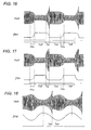
- FIGS. 16 and 17 illustrate further modified dimming controls which are identical to the above embodiment except that the control signal gives the driving frequency f inv which varies continuously along exponential curves respectively during the falling phase PFA in the end of the first period Ton and during the starting period Tst.
- FIG. 18 illustrates a still further modified dimming control which is identical to the above embodiment except that the control signal gives the driving frequency f inv which varies continuously along a sinusoidal curve over the entire period ranging from the starting period Tst, through the first period Ton, to the second period Toff.
- the lamp dimming is made by shifting the driving frequency f inv in accordance with the varying dimming ratio.
- the driving frequency f inv is defined to have a period T1 where the frequency is between f2 and f1 (f1 ⁇ f2) and a period T2 where the frequency is between f2 and f3 (f2 ⁇ f3).
- FIG. 20 illustrates a further modification of the control scheme which is identical to the above embodiment except that the control signal gives the driving frequency f inv of a triangular waveform defining the starting period Tst followed by the first period Ton and the second period Toff.
- the present invention is not limited to this particular realization, and may be configured to vary the output of the DC voltage regulator 20 alone or in combination with the driving frequency, as show in FIG. 21 .
- the dimmer controller 60 is shown to give the control signal determining a voltage signal Vc given to the driver 21 of the DC voltage regulator 20 and the driving frequency Vf give to the driver 31 of the inverter 30.
Landscapes
- Discharge-Lamp Control Circuits And Pulse- Feed Circuits (AREA)
- Circuit Arrangements For Discharge Lamps (AREA)
Claims (14)
- Vorschaltgerät für eine elektrodenlose Entladungslampe, wobei das Vorschaltgerät umfaßt:eine Induktionsspule (40), die angepaßt ist, um nahe der Entladungslampe (50) angeordnet zu sein;eine Hochfrequenz-Spannungsversorgung (30), welche die Induktionsspule mit einer elektrischen Hochfrequenzspannung versorgt, um die Lampe zu betreiben; undeinen Dimmer-Regler (60), der als Reaktion auf einen Dimmerbefehl, der ein variierendes Dimmverhältnis bestimmt, ein Steuersignal erzeugt, das eine erste Zeitdauer (Ton) definiert, während der die Spannungsversorgung geregelt wird, um eine Spulenspannung eines ersten Niveaus (V1) an die Induktionsspule zum Betrieb der Lampe zu legen, wobei auf die erste Zeitdauer eine zweite Zeitdauer (Toff) folgt, während der die Spannungsversorgung geregelt wird, um die Spulenspannung eines zweiten Niveaus (V2) anzulegen, das niedriger als das erste Niveau ist und die Lampe nicht aufrechterhalten kann,wobei der Dimmer-Regler derart konfiguriert ist, um das Steuersignal zu erzeugen, welches zwischen der zweiten Zeitdauer und der ersten Zeitdauer eine Anfangszeitdauer (Tst) definiert, während der die Spulenspannung kontinuierlich zunimmt,
dadurch gekennzeichnet, daß
das Steuersignal derart angepaßt ist, um die Spulenspannung des zweiten Niveaus zu erhöhen und eine relative Einschaltdauer der ersten Zeitdauer zu verkürzen mit abnehmendem Dimmverhältnis, um die Leuchtdichte der Entladungslampe über ein vorherbestimmtes Niveau hinaus zu senken. - Vorschaltgerät nach Anspruch 1, wobei
das Steuersignal derart angepaßt ist, um eine relative Einschaltdauer der ersten Zeitdauer zu verkürzen, während das Dimmverhältnis auf das vorherbestimmte Niveau abnimmt, und
das Steuersignal derart angepaßt ist, um die Spulenspannung des zweiten Niveaus zu erhöhen und die relative Einschaltdauer zu verkürzen, während das Dimmverhältnis weiter über das vorherbestimmte Niveau hinaus abnimmt. - Vorschaltgerät nach Anspruch 1, wobei
das Steuersignal derart angepaßt ist, um die Spulenspannung innerhalb dieser Anfangszeitdauer (Tst) vom zweiten Niveau (V2) auf ein drittes Niveau (V3), das höher als das erste Niveau (V1) ist, kontinuierlich zu erhöhen. - Vorschaltgerät nach Anspruch 1, wobei
das Steuersignal derart angepaßt ist, um am Ende der ersten Zeitdauer eine sinkende Phase (PFA) zu definieren, während der die Spulenspannung kontinuierlich auf das zweite Niveau hin abnimmt. - Vorschaltgerät nach Anspruch 1, wobei
das Steuersignal derart angepaßt ist, um eine relative Einschaltdauer der ersten Zeitdauer (Ton) zu verkürzen mit abnehmendem Dimmverhältnis, um die Leuchtdichte der Entladungslampe auf ein vorherbestimmtes Niveau zu senken, und
das Steuersignal derart angepaßt ist, um die Spulenspannung des ersten Niveaus (V1) und die relative Einschaltdauer zu senken, während das Dimmverhältnis abnimmt, um die Leuchtdichte der Entladungslampe weiter über das vorhergestimmte Niveau hinaus zu senken. - Vorschaltgerät nach Anspruch 1, wobei
die Spulenspannung am Anfang der Anfangszeitdauer (Tst) derart angepaßt ist, um zuzunehmen mit zunehmendem Dimmverhältnis, um die Leuchtdichte der Entladungslampe zu erhöhen. - Vorschaltgerät nach Anspruch 1, wobei
das Steuersignal derart angepaßt ist, um ferner eine Voranfangszeitdauer (Tpr), die der Anfangszeitdauer unmittelbar vorhergeht, zu definieren, wobei in dieser Voranfangszeitdauer die Spulenspannung innerhalb eines Bereichs zwischen dem zweiten Niveau (V2) und dem ersten Niveau (V1) zunimmt mit abnehmendem Dimmverhältnis, um die Leuchtdichte der Entladungslampe zu senken. - Vorschaltgerät nach Anspruch 7, wobei
die Spulenspannung vom zweiten Niveau in der Voranfangszeitdauer kontinuierlich zunimmt. - Vorschaltgerät nach Anspruch 3, wobei
das Steuersignal derart angepaßt ist, um das dritte Niveau (V3) zu erhöhen mit abnehmendem Dimmverhältnis, um die Leuchtdichte der Entladungslampe zu senken. - Vorschaltgerät nach Anspruch 9, wobei
das Steuersignal derart angepaßt ist, um zu bewirken, daß das erste Niveau (V1) während der ersten Zeitdauer vom dritten Niveau kontinuierlich abnimmt. - Vorschaltgerät nach Anspruch 1, wobei
die Hochfrequenz-Spannungsversorgung einen Schwingkreis (34, 35, 36) umfaßt, der die Spulenspannung erzeugt, die durch eine an den Schwingkreis angelegte Treibfrequenz bestimmt ist,
das Steuersignal derart angepaßt ist, um die Treibfrequenz zur Regulierung der Spulenspannung zu variieren. - Vorschaltgerät nach Anspruch 1, wobei es ferner umfaßt:eine Gleichspannungsversorgung (20), die der Hochfrequenz-Spannungsversorgung (30) eine Eingangsgleichspannung bereitstellt,wobei das Steuersignal derart angepaßt ist, um die Eingangsgleichspannung zum Regulieren der Spulenspannung zu variieren.
- Vorschaltgerät nach Anspruch 1, wobei
die Hochfrequenz-Spannungsversorgung einen Schwingkreis (34, 35, 36) umfaßt, der die Spulenspannung erzeugt, die durch eine an den Schwingkreis angelegte Treibfrequenz bestimmt ist,
eine Gleichspannungsversorgung (20) umfaßt ist, um der Hochfrequenz-Spannungsversorgung eine Eingangsgleichspannung bereitzustellen,
das Steuersignal derart angepaßt ist, um die Treibfrequenz und die Gleichspannung zu variieren, um die Spulenspannung zu regulieren. - Vorschaltgerät nach Anspruch 11, wobei
die Treibfrequenz innerhalb eines Bereichs von mehreren zehn kHz bis mehreren MHz liegt.
Applications Claiming Priority (3)
| Application Number | Priority Date | Filing Date | Title |
|---|---|---|---|
| JP2003036518 | 2003-02-14 | ||
| JP2003036518A JP4433677B2 (ja) | 2003-02-14 | 2003-02-14 | 無電極放電灯点灯装置 |
| PCT/JP2003/014951 WO2004073360A1 (en) | 2003-02-14 | 2003-11-21 | Dimmable ballast for an electrodeless discharge lamp |
Publications (2)
| Publication Number | Publication Date |
|---|---|
| EP1593289A1 EP1593289A1 (de) | 2005-11-09 |
| EP1593289B1 true EP1593289B1 (de) | 2008-05-07 |
Family
ID=32866331
Family Applications (1)
| Application Number | Title | Priority Date | Filing Date |
|---|---|---|---|
| EP03774163A Expired - Lifetime EP1593289B1 (de) | 2003-02-14 | 2003-11-21 | Dimmbares vorschaltgerät für eine elektrodenlose entladungslampe |
Country Status (6)
| Country | Link |
|---|---|
| US (1) | US7339329B2 (de) |
| EP (1) | EP1593289B1 (de) |
| JP (1) | JP4433677B2 (de) |
| CN (1) | CN100518427C (de) |
| DE (1) | DE60320856D1 (de) |
| WO (1) | WO2004073360A1 (de) |
Families Citing this family (24)
| Publication number | Priority date | Publication date | Assignee | Title |
|---|---|---|---|---|
| JP2006302838A (ja) * | 2005-04-25 | 2006-11-02 | Matsushita Electric Works Ltd | 無電極放電灯点灯装置及び照明器具 |
| JP4720828B2 (ja) * | 2005-09-28 | 2011-07-13 | パナソニック電工株式会社 | 無電極放電ランプ用調光自在電子安定器及び照明器具 |
| JP4710842B2 (ja) * | 2006-03-31 | 2011-06-29 | ウシオ電機株式会社 | 希ガス蛍光ランプ点灯装置 |
| US7667408B2 (en) | 2007-03-12 | 2010-02-23 | Cirrus Logic, Inc. | Lighting system with lighting dimmer output mapping |
| US7288902B1 (en) | 2007-03-12 | 2007-10-30 | Cirrus Logic, Inc. | Color variations in a dimmable lighting device with stable color temperature light sources |
| JP2008269943A (ja) * | 2007-04-19 | 2008-11-06 | Matsushita Electric Works Ltd | 無電極放電灯点灯装置及び照明器具 |
| US8044606B2 (en) * | 2007-08-30 | 2011-10-25 | Delta Electronics, Inc. | Power supply for supplying power to a lamp |
| WO2009069052A1 (en) * | 2007-11-29 | 2009-06-04 | Koninklijke Philips Electronics N.V. | Method and device for driving a gas discharge lamp |
| US7839098B2 (en) * | 2008-05-23 | 2010-11-23 | Osram Sylvania Inc. | Microcontroller based ignition in high frequency ceramic metal halide lamps |
| US9155174B2 (en) | 2009-09-30 | 2015-10-06 | Cirrus Logic, Inc. | Phase control dimming compatible lighting systems |
| US8729811B2 (en) | 2010-07-30 | 2014-05-20 | Cirrus Logic, Inc. | Dimming multiple lighting devices by alternating energy transfer from a magnetic storage element |
| US8536799B1 (en) | 2010-07-30 | 2013-09-17 | Cirrus Logic, Inc. | Dimmer detection |
| US8569972B2 (en) * | 2010-08-17 | 2013-10-29 | Cirrus Logic, Inc. | Dimmer output emulation |
| US8847515B2 (en) | 2010-08-24 | 2014-09-30 | Cirrus Logic, Inc. | Multi-mode dimmer interfacing including attach state control |
| US9307601B2 (en) | 2010-08-17 | 2016-04-05 | Koninklijke Philips N.V. | Input voltage sensing for a switching power converter and a triac-based dimmer |
| EP2636138B1 (de) | 2010-11-04 | 2023-01-18 | Signify Holding B.V. | Gesteuerte verlustleistung bei einem verknüpfungspfad in einem beleuchtungssystem |
| WO2012061769A2 (en) | 2010-11-04 | 2012-05-10 | Cirrus Logic, Inc. | Controlled power dissipation in a switch path in a lighting system |
| EP2681969B1 (de) | 2010-11-16 | 2019-01-09 | Philips Lighting Holding B.V. | Austrittskantendimmerkompatibilität mit hoher dimmerwiderstandsprognose |
| EP2820919A1 (de) | 2012-02-29 | 2015-01-07 | Cirrus Logic, Inc. | Gemischter laststromausgleich für eine led-beleuchtung |
| US9184661B2 (en) | 2012-08-27 | 2015-11-10 | Cirrus Logic, Inc. | Power conversion with controlled capacitance charging including attach state control |
| US9496844B1 (en) | 2013-01-25 | 2016-11-15 | Koninklijke Philips N.V. | Variable bandwidth filter for dimmer phase angle measurements |
| CN105247958B (zh) | 2013-03-14 | 2017-11-24 | 飞利浦照明控股有限公司 | 经由辅助功率耗散电路的受控电子系统功率耗散 |
| US9621062B2 (en) | 2014-03-07 | 2017-04-11 | Philips Lighting Holding B.V. | Dimmer output emulation with non-zero glue voltage |
| US9215772B2 (en) | 2014-04-17 | 2015-12-15 | Philips International B.V. | Systems and methods for minimizing power dissipation in a low-power lamp coupled to a trailing-edge dimmer |
Citations (1)
| Publication number | Priority date | Publication date | Assignee | Title |
|---|---|---|---|---|
| WO2002098186A1 (en) * | 2001-05-25 | 2002-12-05 | Matsushita Electric Works, Ltd. | Electronic ballast for a high intensity discharge lamp |
Family Cites Families (8)
| Publication number | Priority date | Publication date | Assignee | Title |
|---|---|---|---|---|
| US5243261A (en) | 1991-02-07 | 1993-09-07 | U.S. Philips Corporation | Modulated high frequency dimmer circuit with infrared suppression |
| KR940003434A (ko) * | 1992-07-20 | 1994-02-21 | 에프. 제이. 스미트 | 방전 램프 동작 장치 |
| US5561351A (en) * | 1992-10-14 | 1996-10-01 | Diablo Research Corporation | Dimmer for electrodeless discharge lamp |
| JPH06283293A (ja) | 1993-03-30 | 1994-10-07 | Toshiba Lighting & Technol Corp | 無電極放電灯点灯装置 |
| US5874810A (en) * | 1997-09-02 | 1999-02-23 | General Electric Company | Electrodeless lamp arrangement wherein the excitation coil also forms the primary of the feedback transformer used to switch the transistors of the arrangement |
| US6175198B1 (en) | 1999-05-25 | 2001-01-16 | General Electric Company | Electrodeless fluorescent lamp dimming system |
| US6392366B1 (en) * | 2001-09-19 | 2002-05-21 | General Electric Company | Traic dimmable electrodeless fluorescent lamp |
| CN1579115A (zh) * | 2002-02-20 | 2005-02-09 | 松下电器产业株式会社 | 无电极放电灯点亮装置、灯泡形无电极荧光灯和放电灯点亮装置 |
-
2003
- 2003-02-14 JP JP2003036518A patent/JP4433677B2/ja not_active Expired - Fee Related
- 2003-11-21 DE DE60320856T patent/DE60320856D1/de not_active Expired - Lifetime
- 2003-11-21 US US10/544,720 patent/US7339329B2/en not_active Expired - Fee Related
- 2003-11-21 EP EP03774163A patent/EP1593289B1/de not_active Expired - Lifetime
- 2003-11-21 WO PCT/JP2003/014951 patent/WO2004073360A1/en not_active Ceased
- 2003-11-21 CN CNB2003801096942A patent/CN100518427C/zh not_active Expired - Fee Related
Patent Citations (1)
| Publication number | Priority date | Publication date | Assignee | Title |
|---|---|---|---|---|
| WO2002098186A1 (en) * | 2001-05-25 | 2002-12-05 | Matsushita Electric Works, Ltd. | Electronic ballast for a high intensity discharge lamp |
Also Published As
| Publication number | Publication date |
|---|---|
| WO2004073360A1 (en) | 2004-08-26 |
| JP2004247201A (ja) | 2004-09-02 |
| US20060290294A1 (en) | 2006-12-28 |
| DE60320856D1 (de) | 2008-06-19 |
| EP1593289A1 (de) | 2005-11-09 |
| CN100518427C (zh) | 2009-07-22 |
| JP4433677B2 (ja) | 2010-03-17 |
| US7339329B2 (en) | 2008-03-04 |
| CN1748446A (zh) | 2006-03-15 |
Similar Documents
| Publication | Publication Date | Title |
|---|---|---|
| US7339329B2 (en) | Dimmable ballast for an electrodeless discharge lamp | |
| US5365151A (en) | Gas discharge lamp ballast circuit with frequency modulated pulse control | |
| US6452344B1 (en) | Electronic dimming ballast | |
| US8294384B2 (en) | Dimming electronic ballast with preheat current control | |
| US6958580B2 (en) | Electronic ballast for a high intensity discharge lamp | |
| JP4720828B2 (ja) | 無電極放電ランプ用調光自在電子安定器及び照明器具 | |
| CN1457623A (zh) | 用于灯具加热和减光控制的集成电路 | |
| US6657401B2 (en) | Ballast for discharge lamp | |
| US6359393B1 (en) | Dimmer for a gas discharge lamp employing frequency shifting | |
| JP2005504427A (ja) | ランプランアップ調整を行う電子的な安定器 | |
| EP1768468A2 (de) | Beleuchtungsanordnung mit Entladungslampe hoher Intensität, und Beleuchtungsgerät | |
| JPH076889A (ja) | 放電灯点灯装置 | |
| JP2009140766A (ja) | 放電ランプ点灯装置 | |
| JP2001052889A (ja) | 放電灯点灯装置 | |
| JP3814770B2 (ja) | 放電灯点灯装置 | |
| JP2002231483A (ja) | 放電灯点灯装置 | |
| JP2008166297A (ja) | 放電灯点灯装置 | |
| JP2007265813A (ja) | 照明器具 | |
| JP2011060703A (ja) | ランプ点灯装置 | |
| JP2005235619A (ja) | 放電灯点灯装置 | |
| JP2868224B2 (ja) | 負荷制御装置 | |
| JP2010232064A (ja) | 放電灯点灯装置,照明装置 | |
| JP2008234875A (ja) | 放電ランプ点灯装置 | |
| JP2008235084A (ja) | 放電ランプ点灯装置 | |
| JP2000058281A (ja) | 放電灯点灯装置 |
Legal Events
| Date | Code | Title | Description |
|---|---|---|---|
| PUAI | Public reference made under article 153(3) epc to a published international application that has entered the european phase |
Free format text: ORIGINAL CODE: 0009012 |
|
| 17P | Request for examination filed |
Effective date: 20050727 |
|
| AK | Designated contracting states |
Kind code of ref document: A1 Designated state(s): AT BE BG CH CY CZ DE DK EE ES FI FR GB GR HU IE IT LI LU MC NL PT RO SE SI SK TR |
|
| RBV | Designated contracting states (corrected) |
Designated state(s): DE NL |
|
| 17Q | First examination report despatched |
Effective date: 20070608 |
|
| GRAP | Despatch of communication of intention to grant a patent |
Free format text: ORIGINAL CODE: EPIDOSNIGR1 |
|
| GRAS | Grant fee paid |
Free format text: ORIGINAL CODE: EPIDOSNIGR3 |
|
| GRAA | (expected) grant |
Free format text: ORIGINAL CODE: 0009210 |
|
| AK | Designated contracting states |
Kind code of ref document: B1 Designated state(s): DE NL |
|
| REF | Corresponds to: |
Ref document number: 60320856 Country of ref document: DE Date of ref document: 20080619 Kind code of ref document: P |
|
| PLBE | No opposition filed within time limit |
Free format text: ORIGINAL CODE: 0009261 |
|
| STAA | Information on the status of an ep patent application or granted ep patent |
Free format text: STATUS: NO OPPOSITION FILED WITHIN TIME LIMIT |
|
| 26N | No opposition filed |
Effective date: 20090210 |
|
| PGFP | Annual fee paid to national office [announced via postgrant information from national office to epo] |
Ref country code: NL Payment date: 20141010 Year of fee payment: 12 |
|
| REG | Reference to a national code |
Ref country code: NL Ref legal event code: MM Effective date: 20151201 |
|
| PG25 | Lapsed in a contracting state [announced via postgrant information from national office to epo] |
Ref country code: NL Free format text: LAPSE BECAUSE OF NON-PAYMENT OF DUE FEES Effective date: 20151201 |
|
| PGFP | Annual fee paid to national office [announced via postgrant information from national office to epo] |
Ref country code: DE Payment date: 20161116 Year of fee payment: 14 |
|
| REG | Reference to a national code |
Ref country code: DE Ref legal event code: R119 Ref document number: 60320856 Country of ref document: DE |
|
| PG25 | Lapsed in a contracting state [announced via postgrant information from national office to epo] |
Ref country code: DE Free format text: LAPSE BECAUSE OF NON-PAYMENT OF DUE FEES Effective date: 20180602 |