EP1593190B1 - Ständer für elektromotor mit axialem fluss - Google Patents
Ständer für elektromotor mit axialem fluss Download PDFInfo
- Publication number
- EP1593190B1 EP1593190B1 EP04709253A EP04709253A EP1593190B1 EP 1593190 B1 EP1593190 B1 EP 1593190B1 EP 04709253 A EP04709253 A EP 04709253A EP 04709253 A EP04709253 A EP 04709253A EP 1593190 B1 EP1593190 B1 EP 1593190B1
- Authority
- EP
- European Patent Office
- Prior art keywords
- base
- parts
- cores
- stator
- stator according
- Prior art date
- Legal status (The legal status is an assumption and is not a legal conclusion. Google has not performed a legal analysis and makes no representation as to the accuracy of the status listed.)
- Expired - Lifetime
Links
- 230000004907 flux Effects 0.000 title claims description 12
- 239000000696 magnetic material Substances 0.000 claims abstract description 43
- 239000000843 powder Substances 0.000 claims abstract description 39
- 238000003475 lamination Methods 0.000 claims 1
- 230000000630 rising effect Effects 0.000 abstract description 2
- 238000004519 manufacturing process Methods 0.000 description 14
- 230000000295 complement effect Effects 0.000 description 13
- 230000000712 assembly Effects 0.000 description 2
- 238000000429 assembly Methods 0.000 description 2
- 239000000314 lubricant Substances 0.000 description 2
- 239000000203 mixture Substances 0.000 description 2
- 230000000284 resting effect Effects 0.000 description 2
- XEEYBQQBJWHFJM-UHFFFAOYSA-N Iron Chemical compound [Fe] XEEYBQQBJWHFJM-UHFFFAOYSA-N 0.000 description 1
- 239000003638 chemical reducing agent Substances 0.000 description 1
- 238000005056 compaction Methods 0.000 description 1
- 230000002349 favourable effect Effects 0.000 description 1
- 238000010438 heat treatment Methods 0.000 description 1
- 230000010354 integration Effects 0.000 description 1
- 239000006249 magnetic particle Substances 0.000 description 1
- 239000002184 metal Substances 0.000 description 1
- 229910052751 metal Inorganic materials 0.000 description 1
- 239000002923 metal particle Substances 0.000 description 1
- 238000000034 method Methods 0.000 description 1
- 238000012986 modification Methods 0.000 description 1
- 230000004048 modification Effects 0.000 description 1
- 239000002245 particle Substances 0.000 description 1
- 230000002093 peripheral effect Effects 0.000 description 1
- 238000004663 powder metallurgy Methods 0.000 description 1
Images



Classifications
-
- H—ELECTRICITY
- H02—GENERATION; CONVERSION OR DISTRIBUTION OF ELECTRIC POWER
- H02K—DYNAMO-ELECTRIC MACHINES
- H02K1/00—Details of the magnetic circuit
- H02K1/06—Details of the magnetic circuit characterised by the shape, form or construction
- H02K1/12—Stationary parts of the magnetic circuit
- H02K1/14—Stator cores with salient poles
- H02K1/146—Stator cores with salient poles consisting of a generally annular yoke with salient poles
- H02K1/148—Sectional cores
-
- H—ELECTRICITY
- H02—GENERATION; CONVERSION OR DISTRIBUTION OF ELECTRIC POWER
- H02K—DYNAMO-ELECTRIC MACHINES
- H02K1/00—Details of the magnetic circuit
- H02K1/02—Details of the magnetic circuit characterised by the magnetic material
-
- H—ELECTRICITY
- H02—GENERATION; CONVERSION OR DISTRIBUTION OF ELECTRIC POWER
- H02K—DYNAMO-ELECTRIC MACHINES
- H02K21/00—Synchronous motors having permanent magnets; Synchronous generators having permanent magnets
- H02K21/12—Synchronous motors having permanent magnets; Synchronous generators having permanent magnets with stationary armatures and rotating magnets
- H02K21/24—Synchronous motors having permanent magnets; Synchronous generators having permanent magnets with stationary armatures and rotating magnets with magnets axially facing the armatures, e.g. hub-type cycle dynamos
Definitions
- the present invention relates to the general technical field of axial flow electric motors.
- the motors of the aforementioned type comprise a stator having a planar magnetic portion provided with cores extending perpendicularly to said planar portion and a rotor whose axis of rotation is parallel to the axes of extension of the cores.
- Each core receives a coil.
- the coils can be wired to form one or more phases.
- the present invention relates in particular, but not exclusively, to electronically commutated motors.
- stator comprises a mass of metal particles having magnetic properties.
- the stator can be obtained according to a traditional powder metallurgy process, consisting of forming a mixture of particles and lubricant, to uniaxially compress said mixture to obtain a green part, heat said part to pyrolyze the lubricant, possibly sinter said part, then cool it down.
- An axial flow motor stator according to the preamble of claim 1 is known from the document US 2002/067091 .
- the object of the present invention is to provide a stator for axial flow electric motor, whose production is more economical, without the magnetic properties are significantly degraded.
- each core is formed at least partially by one or more of the pieces made from compacted magnetic material powder.
- Each core can be made in one piece. These pieces can form only one of the nuclei.
- Each core then consists of a part assembled with the base, the base may or may not be made from compacted magnetic material powder.
- the interlocking surfaces are then formed around the cores and in the base. These pieces can also form several nuclei. These pieces then form at least part of the base.
- the interlocking surfaces are then formed in the base.
- each core may consist of several parts, these parts being or not from the base.
- a piece may be attached to a protuberance from the base, or in a housing of the base, to form at least partially a core.
- the isotropy of the magnetic properties of the compacted magnetic material powder makes it possible to simplify the production of the cores while benefiting from favorable magnetic properties. It is not necessary for the entire stator to be made from compacted magnetic material powder. Indeed the magnetic flux in the stator base is arranged essentially in the plane of the base. As a result, anisotropic magnetic materials such as magnetic sheets can be used without particular design difficulties for the stator base. On the contrary, the use of compacted magnetic material powder makes it possible to simplify the production of the cores. The use of nested parts makes it possible to reduce the size of the stator elements made from compacted magnetic material powder. Thus the cost of the investments required for the production of the elements made from compacted magnetic material powder can be reduced.
- the engagement surfaces are defined by a generatrix parallel to the axial direction.
- the interlocking surfaces may be salient and / or reentrant. This arrangement facilitates the production of parts obtained from compacted magnetic material powder. This arrangement also makes it possible to obtain a cohesion of the stator for the forces perpendicular to the axial direction.
- the upper face or faces of said parts may be perpendicular to the axial direction, and / or the lower face or faces of said parts may be perpendicular to the axial direction, and / or the lateral face (s) of said parts can be defined by a generatrix parallel to the axial direction.
- the interlocking surfaces are devoid of ridge. This arrangement makes it possible to reduce the resistance to the passage of the magnetic flux and makes it possible to obtain a better conservation of the magnetic flux.
- At least two of the pieces constituting at least partially one of the cores also constitute a part of the base.
- This arrangement makes it possible to use a single type of part to make the stator, and therefore only one type of mold. Said parts can then advantageously constitute several cores derived from a portion of the base, in order to reduce the number of parts to be assembled.
- the interlocking surfaces of said parts are formed in the base.
- This arrangement simplifies the production of parts.
- this interface arrangement contributes to reducing disturbances to the magnetic flux.
- At least one of the pieces constituting at least partially one of the cores comprises a root, respectively a housing, mounted in a housing, respectively on a root, arranged in / on the or one of the parts constituting the base, the surfaces interlocking being respectively formed by a side wall of the root and a side wall of the housing.
- This arrangement makes it possible to reduce the height of the mold or molds of the base when the base is made from compacted magnetic material powder.
- This arrangement also makes it possible to make the base in a magnetic material different from the magnetic material or materials used for the pieces forming the cores.
- the base can for example be made from stacked magnetic sheets while the cores are made from compacted magnetic material powder.
- At least one of the cores has a side wall extending the side wall forming the nesting surface of the root. This arrangement simplifies the production of parts constituting the cores.
- At least one of the housing crosses the or one of the parts constituting at least a portion of the base.
- said housing has no bottom.
- Such housing is opening.
- This arrangement simplifies the production of the component constituting at least a portion of the base.
- This piece can be defined by an upper face, a lower face, and one or more side faces.
- At least one of the cores has an amount surmounted by a cap.
- the cap can then at least partially cover the coil placed around the upright.
- each of the cores has an amount surmounted by a cap.
- This arrangement makes it possible to obtain a larger exchange surface for the magnetic flux between the stator and the rotor, and thus to obtain a larger torque.
- the cores can be made in one or more pieces.
- the amount is not necessarily from the same room as the hat.
- the amount is formed by one or more pieces made from compacted magnetic material powder. This arrangement considerably reduces the eddy currents that contribute to the heating of the magnetic part. Warm ups observed are thus minimal.
- At least one of the parts partially constituting one of the cores comprises a pin, respectively a housing, mounted in a housing, respectively on a pin, formed in / on another of the parts partially constituting said core, the interlocking surfaces being respectively formed by a side wall of the post and a side wall of the housing.
- the one or one of the pieces constituting at least partially the amount of one of the cores is also at least a part of the base.
- the or at least one of the parts constituting the base is made from stacked magnetic sheets. This arrangement makes it possible to reduce the thickness of the base, the permittivity of the magnetic sheet being greater than the permittivity of the compacted magnetic material powders currently available.
- the part or parts constituting the base is / are made (s) from compacted magnetic material powder.
- the base can then in particular be made of several parts, this arrangement to reduce the volume of each of the parts forming part of the base, and thus to limit the size of the press necessary for the production of said parts.
- the base has an annular configuration.
- This arrangement reduces the amount of magnetic material used, without affecting the performance of the engine, the magnetic mass disposed at the center of the base not playing an active role.
- This arrangement also facilitates the integration of another element, such as for example an accelerator or a reducer.
- the stator comprises at least two identical parts made from compacted magnetic material powder. This provision helps to reduce the number of molds needed.
- the nuclei extend from an upper plane of the base.
- the base comprises a lower plane arranged opposite the upper plane.
- the cores have a flat upper face.
- the side walls of the cores are defined by a generatrix parallel to the axial direction.
- the side walls of the base are defined by a generatrix parallel to the axial direction.
- the stator is defined by a first plane forming the lower part of the base, a second plane forming the upper part of the base and a third plane forming the top of the cores, said planes being perpendicular to the axial direction.
- At least one of the parts constituting at least partially one of the cores also constitutes a part of the base. This arrangement makes it possible to promote the circulation of the magnetic flux in the base. The interface between the two parts can be largely normal to the magnetic flux.
- At least one of the parts constituting the base can be made from stacked magnetic sheets, for example a part devoid of cores intended to receive the coils.
- the base is made of several assembled parts having interlocking surfaces.
- the figure 1 shows a stator 1 and a rotor 5 for an axial flow electric motor, in particular with electronic commutation.
- the stator 1 is made from magnetic material powder such as Somalloy 500 or 550 type iron powder from the company Hôganâs.
- the stator 1 comprises a base 2 on which rise the cores 3 in an axial direction 10.
- the axial direction 10 corresponds to the axis of rotation of the rotor 5.
- the stator 1 comprises nine cores 3.
- the cores 3 are arranged in 2.
- Each core 3 is provided to receive a coil for transmitting the magnetic flux to a permanent magnet 6 of the rotor 5.
- the coils 4 may in particular be supplied with three-phase.
- the permanent magnet 6 is mounted on a metal support 7 for closing the magnetic flux.
- the permanent magnet 6 comprises for example six poles. Three of these poles 6a, 6b, 6c are visible at the figure 1 .
- the base 2 is annular and has a central passage 20.
- the cores 3 are arranged in a circle around the passage 20.
- the base 2 comprises a flat bottom face 21 and a planar upper face 22 of which the cores 3 are raised.
- the lower 21 and upper 22 faces are connected by an outer lateral face 23 and by a inner side face 24.
- the lateral faces 23, 24 of the base 2 and the lateral face 31 of the cores 3 are defined by generatrices moving in the axial direction 10.
- the lower 21 and upper 22 faces of the base 2 and the upper faces 30 of the cores 3 are planar.
- the lower 21 and upper 22 faces of the base 2 and the upper faces 30 of the cores 3 are perpendicular to the axial direction 10.
- the stator 1 consists of several pieces 11, 12, 13, which are better visible at the figure 2 .
- Each part 11, 12, 13 comprises three cores 3 and forms part of the base 2.
- Each part 11, 12, 13 has two assembly conformations 14, 15 designed to fit respectively with an assembly conformation 15. another of the parts 12, 13, 11 and with an assembly conformation 14 of the other parts 13, 11, 12.
- the assembly conformations 14 are reentrant and assembly conformations 15 are prominent.
- Each assembly conformation 14, 15 has an interlocking surface 16, 17 defined by a generatrix parallel to the axial direction 10.
- the assembly conformations 14, 15 have a tail-like shape. dovetail with rounded corner connections.
- the interlocking surfaces 16, 17 of the assembly conformations 14, 15 are devoid of edges.
- the parts 71, 12, 13 are made from compacted magnetic material powder.
- a chamber corresponding to the shape of the desired part is composed of a fixed peripheral side wall in which can slide a lower cylinder and an upper cylinder.
- the compacting of the powder is carried out for example at a pressure of 400 MPa.
- the compacted part is then placed for example in an oven having a temperature of 500 ° C. ventilated atmosphere for half an hour.
- the precision obtained for the parts 11, 12, 13 is sufficient to allow assembly without subsequent rectification.
- the cohesion of the parts 11, 12, 13 is sufficient to ensure the strength of the assembly.
- the lateral faces 23, 24, 31 and the engagement surfaces 16, 17 defined by generatrices moving along the axial direction 10 as well as the planar faces 21, 22, 30 make it possible to simplify the design of the tooling used for the production. parts 11, 12, 13 of the stator 1.
- the three parts 11, 12, 13 are advantageously identical and can be obtained from the same mold.
- the stator 1 is composed of the parts 11, 12, 13 assemblies having interlocking surfaces 16, 17.
- the parts 11, 12, 13 constitute the cores 3.
- the parts 11, 12, 13 do not necessarily comprise three cores, and are not necessarily three in number.
- each room may have only one kernel.
- a core may be formed by assembling at least two pieces, at least one of which constitutes a part of the base.
- the figure 3 presents a second embodiment of a stator 1 'comprising cores 3' rising from a base 2 'in an axial direction 10'. Each core 3 'is provided to receive a coil, not shown in FIG. figure 3 .
- the base 2 ' is annular and has a central passage 20'.
- the base 2 ' is made in one piece 40 having a lower face 21, an upper face 22, an outer side face 23, an inner side face 24 and a central passage 20'.
- the piece 40 is made from compacted magnetic material powder.
- the upper face 22 of the part 40 has housings 41 provided to each receive a part 45 forming one of the cores 3 '.
- the parts 45 are made from compacted magnetic material powder.
- Each piece 45 has a root 46 intended to be mounted in one of the dwellings 41.
- the housings 41 comprise a bottom wall 42 and a side wall 43.
- the roots 46 comprise a bottom wall 47 and a side wall 48.
- the bottom walls 42 and the bottom walls 47 are perpendicular to the axial direction 10 '.
- the side walls 43, 48 are defined by a generatrix parallel to the axial direction 10 '.
- the bottom walls 42 and the side walls 43 form interlocking surfaces 44 of the parts 40.
- the lower walls 47 and the side walls 48 form interlocking surfaces 49 of the parts 45.
- the interlocking surfaces 44, 49 are advantageously defined by a generatrix parallel to the axial direction 10 '.
- the interlocking surfaces 44, 49 are advantageously devoid of edges.
- the interlocking surfaces 44 are reentrant.
- the interlocking surfaces 49 are prominent.
- the pieces 45 mounted in the piece 40 have an upper face 30 and a lateral face 31.
- the lateral face 31 extends the side wall 48 of the root 46.
- This arrangement makes it possible to reduce the height of the mold used for the production of the part 40 forming the base 2 ', because the cores 3' do not belong to the part 40.
- the parts 45 forming the cores 3 ' are advantageously identical .
- the production of the molds of the pieces 45 forming the cores 3 ' is particularly simple, since the lateral faces 31 extend the lateral walls 48.
- the stator 1 ' is composed of the part 40 and the assembled parts 45, the part 40 having interlocking surfaces 44 and the parts 45 having interlocking surfaces 49.
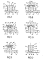
- FIGS. 4 to 6 illustrate alternative embodiments relating to the connection between the part forming the base 2 'of the stator and the parts forming the cores 3' of the stator.
- the pieces forming the cores 3 ' are made from compacted magnetic material powder.
- the embodiment variant illustrated in figure 4 differs from the previous embodiment in that the base 2 'is formed by a part 40' having housings 41 'opening into the lower face 21. housings 41 'pass through the base 2' and have a side wall 43 '.
- Each of the cores 3 ' is formed by a piece 45' having a root 46 '.
- the root 46 ' has a side wall 48' whose height is greater than the height of the side wall 48 of the root 46 of the second embodiment.
- the bottom wall 47 'of the root 46' is in the plane of the lower face 21 of the piece 40 'forming the base 2'.
- the side walls 43 'of the housings 41' form interlocking surfaces 44 'of the parts 40' and the side walls 48 'of the roots 46' form interlocking surfaces 49 'of the parts 45'.
- the interlocking surfaces 44 'are reentrant and the interlocking surfaces 49' are projecting. The greater height of the interlocking surfaces 44 ', 49' allows a better assembly of the parts 45 'in the piece 40'.
- the lateral face 31 extends the side wall 48 'of the root 46'.
- the base 2 ' is formed by a piece 40 "having housings 41" having a smaller section than the section of the cores 3'.
- Each of the cores 3 ' is formed by a piece 45 “having a root 46" having a lower wall 47 “of smaller surface area than the lower wall 47 of the second exemplary embodiment Root 46" is surrounded by a bottom face 32 " perpendicular to the axial direction 10 'The lower face 32 "is annular and comes on the upper face 22 of the workpiece 40"
- the root 46 has a side wall 48" connected to the lateral face 31 by the lower face 32 " .
- the bottom walls 42 "and the side walls 43" of the housings 41 "form interlocking surfaces 44" of the parts 40 "The bottom walls 47” and the side walls 48 “of the roots 46” form interlocking surfaces 49 "pieces 45".
- the interlocking surfaces 44 are reentrant and the interlocking surfaces 49" are prominent. Due to the smaller size of the bottom walls 42 “and the lower walls 47", the engagement surfaces 44 ", 49” also allow a very good assembly of the parts 45 "in the part 40".
- the housing 41 "could open into the lower wall 21 of the workpiece 40".
- the face lateral 31 does not necessarily extend the side wall 48 "of the root 46".
- the base 2 ' is formed by a piece 40 "' having roots 46"', or protuberances, issuing from the upper face 22 and the housings 41 "' are formed in the pieces 45 '' forming the cores 3 '.
- Each housing 41 '" is surrounded by a lower face 32'" perpendicular to the axial direction 10 '.
- the lower face 32 "'comes on the upper face 22 of the piece 40"'.
- the lateral face 31 extends the side wall 48 "'of the root 46"'.
- the upper walls 47 "and the side walls 48"'of the roots 46 "' form interlocking surfaces 44"'of the parts 40 "'
- the interlocking surfaces 44 "'are projecting and the interlocking surfaces 49"' are reentrant. Due to the smaller size of the bottom walls 42 "'and the lower walls 47"', the interlocking surfaces 44 "', 49”' also allow a very good assembly of the parts 45 '"in the parts 40" .
- the housing 41 "'could open into the upper wall 30 of the piece 45"'.
- the side face 31 does not necessarily extend the side wall 48 "'of the root 46"'.
- the embodiment variant illustrated in figure 7 differs from the embodiment illustrated in figure 3 in that the cores 3 'are formed by a part 60 having a cap 61 extending laterally above the side wall 31 belonging to a post 65.
- the top wall 30 of the part 60 forms the top wall of the cap 61
- the upper wall 30 is perpendicular to the axial direction 10 '.
- the cap 61 has a side wall 62 defined by a generatrix parallel to the axial direction 10 '.
- the cap 61 has a bottom wall 63 perpendicular to the direction axial 10 '.
- the lower wall 63 connects the side wall 62 and the side wall 31.
- the cap 61 is formed by a piece 70 'assembled with a piece 75' forming the amount 65 of the core 3 '.
- the piece 75 ' is assembled with the piece 40 forming the base 2'.
- the piece 70 ' has a housing 71' receiving a pin 76 'from the upper face 30' of the piece 75 '.
- the pin 76 ' has an upper wall 77' and a side wall 78 '.
- the housing 71 ' has a side wall 73'.
- the part 70 ' has a bottom wall 72' resting on the upper wall 30 'of the part 75'.
- the upper wall 77 ' is perpendicular to the axial direction 10'.
- the side walls 73 ', 78' form interlocking surfaces 74 ', 79' advantageously defined by generatrices parallel to the axial direction 10 '.
- the interlocking surfaces 74 ' are reentrant and the interlocking surfaces 79' are projecting.
- the interlocking surfaces 74 ', 79' are advantageously devoid of edges.
- the housing 71 'does not necessarily cross the part 70'.
- the part 70' is not necessarily made from compacted magnetic material powder, but can for example be made from a stack of magnetic sheets.
- the embodiment variant illustrated in figure 9 differs from the previous variant in that the piece 70 "forming the cap 61 has a pin 76" from the bottom wall 72 "and in that the piece 60" forming the upright 65 has a housing 71 "receiving the pin 76" .
- the piece 70 has a lower face 63" resting on the upper face 30 "of the piece 75".
- the post 76 has a bottom wall 77" and a side wall 78 ".
- the housing 71" has a bottom wall 72 "and a side wall 73".
- the upper wall 77 is perpendicular to the axial direction 10 ', the side walls 73", 78 "form interlocking surfaces 74", 79 ", the interlocking surfaces 74" are protruding and the interlocking surfaces 79 "are re-entrant .
- the housing 71 can cross the room 75".
- the part 70 can form part of the upright 65.
- the part 75 is not necessarily made from compacted magnetic material powder, but can for example be made from a stack of magnetic sheets.
- variants of embodiment illustrated in Figures 10 and 11 are variants of the second embodiment illustrated in FIG. figure 3 in which a portion of the cores is integral with the base.
- the embodiment variant illustrated in figure 10 differs from the embodiment variant illustrated in figure 8 in that the base 2 'and the upright 65' of the core 3 'are formed by a piece 80' made from compacted magnetic material powder, and that the part 70 '''forming the cap 61 of the core 3 is made from a stack of magnetic sheets.
- the piece 70 ''' has a housing 71'''.
- the housing 71 '"does not necessarily cross the part 70"'.
- the part 70 "' is not necessarily made from a stack of magnetic sheets, but can for example be made from compacted magnetic material powder.
- the embodiment variant illustrated in figure 11 differs from the embodiment variant illustrated in figure 9 in that the base 2 'and the upright 65 "of the core 3' are made in one piece 80" made from compacted magnetic material powder.
- the housing 71 "can cross the room 80".
- the embodiment variant illustrated in figure 12 differs from the example of realization illustrated at the figure 4 in that the base 2 'is formed by a piece 90 obtained from a stack of magnetic sheets.
- the part 90 comprises housings 91 receiving the root 46 'of one of the pieces 45' forming the cores 3 '.
- the housings 91 form reentrant interlocking surfaces 94 cooperating with interlocking surfaces 49 'protruding from the roots 46'.
- the housings 91 do not necessarily pass through the part 90.
- the root 46 'does not necessarily extend the side wall 31.
- the base 2' may comprise or be formed by several pieces obtained from a stack of magnetic sheets. Also as a complementary variant one or more pieces 45 'forming one of the cores can also form a part of the base 2'.
- the interlocking surfaces are devoid of edges and are defined by a generatrix parallel to the axial direction 10 '.
- the parts 40, 40 ', 40 ", 40"', 60 constitute entirely the cores 3 '.
- the base 2 'of the stator can be made in several parts, in particular in several parts obtained by compaction of powder of magnetic material.
- the interlocking between the parts of the base 2 'can especially be in accordance with the interlocking parts 11, 12, 13 of the base 2 of the first embodiment.
- other interlockings are possible, such as a part 101 surrounding a part 100, as illustrated for example on the figure 13 .
- the figure 14 illustrates such a variant, in which the base 2 'comprises a part 100 having an amount 65 "' forming one of the cores 3 ', the base 2' also comprises a part 101.
- the parts 100, 101 assembled have interlocking surfaces 102, 103.
- the piece 101 is devoid of amount forming a core.
- the piece 101 may be annular.
- several identical or different pieces 101 may be assembled together or with parts 100 comprising at least part of a core 3 '.
- the part or parts 101 may be made from compacted magnetic material powder or from a stack of magnetic sheets. Parts 100 comprising part of the base 2 'are made from compacted magnetic material powder.
- the figure 15 illustrates another variant of the aforementioned type, in which the core 3 'corresponds to the core of the variant of the figure 10 .
- the amount 65 'of the piece 100' corresponds to the amount 65 'of the piece 80'.
- the figure 16 illustrates another variant of the aforementioned type, in which the core 3 'corresponds to the core of the variant of the figure 11 .
- the amount 65 "of the coin 100" corresponds to the amount 65 "of the coin 80".
- the engagement surfaces 16, 17; 102, 103 are not necessarily provided solely in the base 2, 2 '.
- the interlocking surfaces 16, 17; 102, 103 may for example pass through at least one of the cores 3, 3 '.
- the interlocking surfaces may comprise one or more edges. Also as an additional variant for one or the other of the embodiments, the interlocking surfaces are not necessarily defined by a generatrix parallel to the axial direction, but may in particular be frustoconical.
- the base 2, 2 'of the stator 1 does not necessarily comprise a passage 20, 20'.
- the number of poles of the stator 1 is not necessarily nine; the number of poles of the rotor 5 is not necessarily six.
- the motor supply is not necessarily three-phase.
- the interlocking surfaces may comprise several projecting parts and / or several reentrant parts.
Landscapes
- Engineering & Computer Science (AREA)
- Power Engineering (AREA)
- Iron Core Of Rotating Electric Machines (AREA)
- Motor Or Generator Frames (AREA)
- Manufacture Of Motors, Generators (AREA)
Claims (20)
- Stator für einen Elektromotor mit Axialfluss, der zumindest teilweise aus gepresstem Pulver aus magnetischem Material hergestellt ist und Kerne (3; 3') aufweist, die sich ausgehend von einer Basis (2; 2') in eine axiale Richtung (10; 10') nach oben erstrecken, wobei die Kerne (3; 3') kreisförmig an der Basis (2; 2') angeordnet sind, jeder Kern (3; 3') dazu vorgesehen ist, eine Spule (4) aufzunehmen, der Stator aus zusammengesetzten Teilen (11, 12, 13; 100, 101; 100', 101; 100", 101) besteht, die Einsteckflächen (16, 17; 44, 49; 44', 49'; 44", 49"; 44"', 49"'; 74', 79'; 74", 79"; 94, 49'; 102, 103) aufweisen, und einige der Teile (11, 12, 13; 100; 100';100"), die zumindest teilweise die Kerne (3; 3') bilden, aus gepresstem Pulver aus magnetischem Material hergestellt sind, dadurch gekennzeichnet, dass die Basis (2; 2') aus mehreren zusammengesetzten Teilen (11, 12, 13; 100, 101; 100', 101; 100", 101) besteht, die zumindest einige der Einsteckflächen (16, 17; 102, 103) aufweisen, und dass die Basis (2; 2') um die Kerne (3; 3') herum aus gepresstem Pulver aus magnetischem Material hergestellt ist.
- Stator nach Anspruch 1, dadurch gekennzeichnet, dass die Basis (2; 2') ringförmig ist.
- Stator nach Anspruch 2, dadurch gekennzeichnet, dass die Einsteckflächen (16, 17) der Teile (11, 12, 13) die ringförmige Basis (2; 2') in Stücke teilen.
- Stator nach einem der Ansprüche 1 bis 3, dadurch gekennzeichnet, dass die Basis (2; 2') aus mehreren zusammengesetzten Teilen (11, 12, 13; 100, 101; 100', 101; 100", 101) besteht, die aus gepresstem Pulver aus magnetischem Material hergestellt sind und zumindest einige der Einsteckflächen (16, 17; 102, 103) aufweisen.
- Stator nach Anspruch 4, dadurch gekennzeichnet, dass mindestens eines der Teile (45; 45'; 45"), das zumindest teilweise einen der Kerne (3') bildet, einen Fußabschnitt (46; 46'; 46") bzw. eine Aufnahme (41''') aufweist, der in einer Aufnahme (41; 41'; 41") bzw. die an einem Fußabschnitt (46''') angebracht ist, die bzw. der in/an dem oder einem der Teile (40; 40'; 40"; 40''') ausgebildet ist, welches die Basis (2') bildet, wobei die Einsteckflächen (44, 49; 44', 49'; 44", 49"; 44"'; 49"') durch eine Seitenwand (48; 48'; 48"; 48"') des Fußbereichs bzw. durch eine Seitenwand (43; 43'; 43"; 43"') der Aufnahme gebildet sind.
- Stator nach Anspruch 5, dadurch gekennzeichnet, dass mindestens einer der Kerne (3') eine Seitenwand (31) aufweist, die die Seitenwand (48; 48') verlängert, welche die Einsteckfläche (49; 49') des Fußbereichs (46; 46') bildet.
- Stator nach Anspruch 5 oder 6, dadurch gekennzeichnet, dass mindestens eine der Aufnahmen (41') das Teil oder eines der Teile (40') durchquert, welches zumindest einen Abschnitt der Basis (2') bildet.
- Stator nach einem der Ansprüche 1 bis 3, dadurch gekennzeichnet, dass die Basis (2; 2') aus mehreren zusammengesetzten Teilen (11, 12, 13; 100, 101; 100', 101; 100", 101) besteht, die einige der Einsteckflächen (16, 17; 102, 103) aufweisen, und dass die Teile (11, 12, 13; 100; 100'; 100"), die zumindest teilweise die Kerne (3; 3') bilden, einen Abschnitt der Basis (2; 2') aufweisen.
- Stator nach Anspruch 8, dadurch gekennzeichnet, dass sich die Teile (11, 12, 13; 100; 100'; 100"), die zumindest teilweise die Kerne (3; 3') bilden, um die Kerne (3; 3') herum erstrecken, um einen Abschnitt der Basis zu bilden (2; 2').
- Stator nach Anspruch 8 oder 9, dadurch gekennzeichnet, dass die Basis (2') ein Teil (101) aufweist, das aus gestapelten Magnetblechen hergestellt ist und keine Säule aufweist, die einen Kern bildet.
- Stator nach einem der Ansprüche 1 bis 10, dadurch gekennzeichnet, dass die Einsteckflächen (16, 17; 44, 49; 44', 49'; 44", 49"; 44"', 49"'; 74', 79'; 74", 79"; 94, 49'; 102, 103) durch eine zur Axialrichtung (10; 10') parallel verlaufende Mantellinie definiert sind.
- Stator nach einem der Ansprüche 1 bis 11, dadurch gekennzeichnet, dass die Einsteckflächen (16, 17; 44, 49; 44', 49'; 44", 49"; 44"', 49"'; 74', 79'; 74", 79"; 94, 49'; 102, 103) kantenlos sind.
- Stator nach einem der Ansprüche 1 bis 12, dadurch gekennzeichnet, dass jeder Kern (3; 3') durch eines oder mehrere der Teile (11, 12, 13; 45; 45'; 45"; 45"'; 60; 70'; 75'; 70"; 75"; 70", 80"; 100; 100'; 100") gebildet ist, welche aus gepresstem Pulver aus magnetischem Material hergestellt sind.
- Stator nach einem der Ansprüche 1 bis 13, dadurch gekennzeichnet, dass mindestens zwei der Teile (11, 12, 13; 80'; 80"; 100; 100'; 100"), die zumindest teilweise einen der Kerne (3; 3') bilden, auch einen Abschnitt der Basis (2; 2') bilden.
- Stator nach Anspruch 14, dadurch gekennzeichnet, dass die Einsteckflächen (16, 17; 102, 103) der Teile (11, 12, 13; 100, 101; 100', 101; 100", 101) in der Basis (2; 2') ausgebildet sind.
- Stator nach einem der Ansprüche 1 bis 15, dadurch gekennzeichnet, dass mindestens einer der Kerne (3') eine Säule (65; 65'; 65") aufweist, über der eine Kappe (61) angeordnet ist.
- Stator nach Anspruch 16, dadurch gekennzeichnet, dass mindestens eines der Teile (75'; 75"; 80'; 80"), das teilweise einen der Kerne (3') bildet, einen Zapfen (76') bzw. eine Aufnahme (71 ") aufweist, der in einer Aufnahme (71') bzw. die an einem Zapfen (76") angebracht ist, die bzw. der in/an einem anderen der Teile (70'; 70"; 70"') ausgebildet ist, das den Kern (3') teilweise bildet, wobei die Einsteckflächen (74', 79'; 74", 79") durch eine Seitenwand (78'; 78") des Zapfens bzw. durch eine Seitenwand (73'; 73") der Aufnahme gebildet sind.
- Stator nach einem der Ansprüche 1 bis 17, dadurch gekennzeichnet, dass das Teil oder eines der Teile (11, 12, 13; 80'; 80"; 100; 100'; 100"), das die Säule (65'; 65") eines der Kerne (3; 3') zumindest teilweise bildet, auch mindestens einen Abschnitt der Basis (2; 2') bildet.
- Stator nach einem der Ansprüche 1 bis 18, dadurch gekennzeichnet, dass er mindestens zwei identische Teile (11, 12, 13; 45; 45'; 45"; 45"'; 60; 70'; 70"; 70"'; 75'; 75") aufweist, die aus gepresstem Pulver aus magnetischem Material hergestellt sind.
- Stator nach einem der Ansprüche 1 bis 19, dadurch gekennzeichnet, dass mindestens eines der Teile (11, 12, 13; 80'; 80"; 100; 100'; 100"), das einen der Kerne (3; 3') zumindest teilweise bildet, auch einen Abschnitt der Basis (2; 2') bildet.
Applications Claiming Priority (3)
| Application Number | Priority Date | Filing Date | Title |
|---|---|---|---|
| FR0301659 | 2003-02-12 | ||
| FR0301659A FR2851088B1 (fr) | 2003-02-12 | 2003-02-12 | Stator pour moteur electrique a flux axial |
| PCT/FR2004/000290 WO2004075376A2 (fr) | 2003-02-12 | 2004-02-09 | Stator pour moteur electrique a flux axial |
Publications (2)
| Publication Number | Publication Date |
|---|---|
| EP1593190A2 EP1593190A2 (de) | 2005-11-09 |
| EP1593190B1 true EP1593190B1 (de) | 2008-07-16 |
Family
ID=32731974
Family Applications (1)
| Application Number | Title | Priority Date | Filing Date |
|---|---|---|---|
| EP04709253A Expired - Lifetime EP1593190B1 (de) | 2003-02-12 | 2004-02-09 | Ständer für elektromotor mit axialem fluss |
Country Status (6)
| Country | Link |
|---|---|
| EP (1) | EP1593190B1 (de) |
| AT (1) | ATE401690T1 (de) |
| DE (1) | DE602004015077D1 (de) |
| ES (1) | ES2309497T3 (de) |
| FR (1) | FR2851088B1 (de) |
| WO (1) | WO2004075376A2 (de) |
Cited By (3)
| Publication number | Priority date | Publication date | Assignee | Title |
|---|---|---|---|---|
| WO2018162072A1 (en) * | 2017-03-10 | 2018-09-13 | Arcelik Anonim Sirketi | Permanent magnet axial-flux electric machine with auxiliary winding arrangement |
| US20210167641A1 (en) * | 2018-07-27 | 2021-06-03 | Sumitomo Electric Industries, Ltd. | Core, stator, and rotating electrical machine |
| US11804763B2 (en) * | 2019-09-20 | 2023-10-31 | Seiko Epson Corporation | Axial gap motor |
Families Citing this family (8)
| Publication number | Priority date | Publication date | Assignee | Title |
|---|---|---|---|---|
| JP2006050745A (ja) * | 2004-08-03 | 2006-02-16 | Nissan Motor Co Ltd | アキシャルギャップ回転電機 |
| US8283832B2 (en) * | 2004-10-25 | 2012-10-09 | Novatorque, Inc. | Sculpted field pole members and methods of forming the same for electrodynamic machines |
| JP4716060B2 (ja) * | 2009-11-30 | 2011-07-06 | 株式会社富士通ゼネラル | アキシャルギャップ型電動機およびポンプ装置 |
| GB201301305D0 (en) * | 2013-01-24 | 2013-03-06 | Gkn Evo Edrive Systems Ltd | Electrical machines |
| DE102014203945A1 (de) * | 2014-03-05 | 2015-09-10 | Robert Bosch Gmbh | Statorelement zum Aufbau einer Statoranordnung für eine elektrische Maschine, Statoranordnung und Verfahren zum Aufbau einer Statoranordnung |
| DE102015223766A1 (de) | 2015-11-30 | 2017-06-01 | Baumüller Nürnberg GmbH | Elektrische Maschine |
| WO2018162073A1 (en) | 2017-03-10 | 2018-09-13 | Arcelik Anonim Sirketi | Permanent magnet axial-flux electric machine stator and rotor assemblies |
| DE102017204401A1 (de) * | 2017-03-16 | 2018-09-20 | Brose Fahrzeugteile GmbH & Co. Kommanditgesellschaft, Würzburg | Segmentierter Stator für eine oder in einer Axialflussmaschine |
Family Cites Families (4)
| Publication number | Priority date | Publication date | Assignee | Title |
|---|---|---|---|---|
| JPH10145990A (ja) * | 1996-11-14 | 1998-05-29 | Meidensha Corp | アウタロータモータの固定子鉄心 |
| US6445105B1 (en) * | 1999-04-06 | 2002-09-03 | General Electric Company | Axial flux machine and method of fabrication |
| JP2001037107A (ja) * | 1999-07-23 | 2001-02-09 | Hitachi Ferrite Electronics Ltd | モータ用ヨーク |
| DE10048492A1 (de) * | 2000-09-29 | 2002-04-11 | Linde Ag | Axialfeldmaschine |
-
2003
- 2003-02-12 FR FR0301659A patent/FR2851088B1/fr not_active Expired - Fee Related
-
2004
- 2004-02-09 AT AT04709253T patent/ATE401690T1/de not_active IP Right Cessation
- 2004-02-09 EP EP04709253A patent/EP1593190B1/de not_active Expired - Lifetime
- 2004-02-09 WO PCT/FR2004/000290 patent/WO2004075376A2/fr not_active Ceased
- 2004-02-09 DE DE602004015077T patent/DE602004015077D1/de not_active Expired - Lifetime
- 2004-02-09 ES ES04709253T patent/ES2309497T3/es not_active Expired - Lifetime
Cited By (4)
| Publication number | Priority date | Publication date | Assignee | Title |
|---|---|---|---|---|
| WO2018162072A1 (en) * | 2017-03-10 | 2018-09-13 | Arcelik Anonim Sirketi | Permanent magnet axial-flux electric machine with auxiliary winding arrangement |
| US20210167641A1 (en) * | 2018-07-27 | 2021-06-03 | Sumitomo Electric Industries, Ltd. | Core, stator, and rotating electrical machine |
| US11770034B2 (en) * | 2018-07-27 | 2023-09-26 | Sumitomo Electric Industries, Ltd. | Core for, rotating electrical machine |
| US11804763B2 (en) * | 2019-09-20 | 2023-10-31 | Seiko Epson Corporation | Axial gap motor |
Also Published As
| Publication number | Publication date |
|---|---|
| WO2004075376A2 (fr) | 2004-09-02 |
| FR2851088B1 (fr) | 2006-01-27 |
| ATE401690T1 (de) | 2008-08-15 |
| ES2309497T3 (es) | 2008-12-16 |
| FR2851088A1 (fr) | 2004-08-13 |
| DE602004015077D1 (de) | 2008-08-28 |
| WO2004075376A3 (fr) | 2005-01-06 |
| EP1593190A2 (de) | 2005-11-09 |
Similar Documents
| Publication | Publication Date | Title |
|---|---|---|
| EP1593190B1 (de) | Ständer für elektromotor mit axialem fluss | |
| EP3827500B1 (de) | Asymmetrische pole eines rotor einer elektrischen maschine | |
| EP1300207A2 (de) | Herstellungsverfahren und Verbundrotoranordnung aus Metallpulver für Synchron-Reluktanzmaschine | |
| FR3046888A1 (fr) | Stator pour machine electromagnetique a flux axial avec des portions unitaires formant une couronne du stator | |
| JP2004248496A (ja) | ブラシレスモータ及びそのブラシレスモータ用ロータの製造方法 | |
| WO2009069463A1 (ja) | 固定子積層鉄心及びその製造方法 | |
| FR2859049A1 (fr) | Moteur asynchrone et rotor pour celui-ci | |
| FR3008912A1 (fr) | Carter de turbomachine et procede de fabrication | |
| JP2007259609A (ja) | モータ | |
| FR2994036A1 (fr) | Bobinage pour un element stator d'un moteur a aimants permanents a au moins une branche rigide et d'un seul tenant et son procede de fabrication | |
| CN1960138B (zh) | 不用轮毂的转子组件的结构及其装配方法 | |
| FR2650712A1 (fr) | Dispositif de champ pour machine electrique tournante | |
| CA2847102A1 (fr) | Couvercle de connexion d'ensembles de stockage d'energie | |
| FR2533365A1 (fr) | Procede pour la realisation de noyaux annulaires pour unites de deviation, ainsi que support ceramique a utiliser pour ce procede | |
| EP3685492B1 (de) | Isthmi für die magnetischen brücken eines elektrischen maschinenrotors | |
| EP3522334A1 (de) | Magnetschaltkreis für element einer elektrisch umlaufenden maschine, entsprechendes verfahren und entsprechende elektrische maschine | |
| EP3198617B1 (de) | Magnetkern eines rotierenden transformators | |
| EP2965406A2 (de) | Elektrische maschine mit einem kupplungsflansch | |
| WO2003012954A3 (fr) | Machine electrique avec stator a poles griffes | |
| WO2023232437A1 (fr) | Ensemble et transformateur électrique planaire | |
| EP3563468A1 (de) | Elektromagnetische anordnung mit mehrphasiger struktur | |
| WO2012080586A1 (fr) | Stator pour génératrice électrique | |
| FR2757703A1 (fr) | Rotor pour moteur electrique et son procede de fabrication | |
| EP4492971B1 (de) | Rahmen mit magnetischen eigenschaften für einen bienenstock | |
| CN205113945U (zh) | 多功能储物盒 |
Legal Events
| Date | Code | Title | Description |
|---|---|---|---|
| PUAI | Public reference made under article 153(3) epc to a published international application that has entered the european phase |
Free format text: ORIGINAL CODE: 0009012 |
|
| 17P | Request for examination filed |
Effective date: 20050808 |
|
| AK | Designated contracting states |
Kind code of ref document: A2 Designated state(s): AT BE BG CH CY CZ DE DK EE ES FI FR GB GR HU IE IT LI LU MC NL PT RO SE SI SK TR |
|
| AX | Request for extension of the european patent |
Extension state: AL LT LV MK |
|
| DAX | Request for extension of the european patent (deleted) | ||
| GRAP | Despatch of communication of intention to grant a patent |
Free format text: ORIGINAL CODE: EPIDOSNIGR1 |
|
| GRAS | Grant fee paid |
Free format text: ORIGINAL CODE: EPIDOSNIGR3 |
|
| GRAA | (expected) grant |
Free format text: ORIGINAL CODE: 0009210 |
|
| AK | Designated contracting states |
Kind code of ref document: B1 Designated state(s): AT BE BG CH CY CZ DE DK EE ES FI FR GB GR HU IE IT LI LU MC NL PT RO SE SI SK TR |
|
| REG | Reference to a national code |
Ref country code: GB Ref legal event code: FG4D Free format text: NOT ENGLISH |
|
| REG | Reference to a national code |
Ref country code: CH Ref legal event code: EP |
|
| REF | Corresponds to: |
Ref document number: 602004015077 Country of ref document: DE Date of ref document: 20080828 Kind code of ref document: P |
|
| REG | Reference to a national code |
Ref country code: IE Ref legal event code: FG4D Free format text: LANGUAGE OF EP DOCUMENT: FRENCH |
|
| REG | Reference to a national code |
Ref country code: ES Ref legal event code: FG2A Ref document number: 2309497 Country of ref document: ES Kind code of ref document: T3 |
|
| PG25 | Lapsed in a contracting state [announced via postgrant information from national office to epo] |
Ref country code: PT Free format text: LAPSE BECAUSE OF FAILURE TO SUBMIT A TRANSLATION OF THE DESCRIPTION OR TO PAY THE FEE WITHIN THE PRESCRIBED TIME-LIMIT Effective date: 20081216 |
|
| PG25 | Lapsed in a contracting state [announced via postgrant information from national office to epo] |
Ref country code: FI Free format text: LAPSE BECAUSE OF FAILURE TO SUBMIT A TRANSLATION OF THE DESCRIPTION OR TO PAY THE FEE WITHIN THE PRESCRIBED TIME-LIMIT Effective date: 20080716 Ref country code: BG Free format text: LAPSE BECAUSE OF FAILURE TO SUBMIT A TRANSLATION OF THE DESCRIPTION OR TO PAY THE FEE WITHIN THE PRESCRIBED TIME-LIMIT Effective date: 20081016 Ref country code: AT Free format text: LAPSE BECAUSE OF FAILURE TO SUBMIT A TRANSLATION OF THE DESCRIPTION OR TO PAY THE FEE WITHIN THE PRESCRIBED TIME-LIMIT Effective date: 20080716 Ref country code: SI Free format text: LAPSE BECAUSE OF FAILURE TO SUBMIT A TRANSLATION OF THE DESCRIPTION OR TO PAY THE FEE WITHIN THE PRESCRIBED TIME-LIMIT Effective date: 20080716 |
|
| REG | Reference to a national code |
Ref country code: IE Ref legal event code: FD4D |
|
| PG25 | Lapsed in a contracting state [announced via postgrant information from national office to epo] |
Ref country code: EE Free format text: LAPSE BECAUSE OF FAILURE TO SUBMIT A TRANSLATION OF THE DESCRIPTION OR TO PAY THE FEE WITHIN THE PRESCRIBED TIME-LIMIT Effective date: 20080716 Ref country code: DK Free format text: LAPSE BECAUSE OF FAILURE TO SUBMIT A TRANSLATION OF THE DESCRIPTION OR TO PAY THE FEE WITHIN THE PRESCRIBED TIME-LIMIT Effective date: 20080716 Ref country code: IE Free format text: LAPSE BECAUSE OF FAILURE TO SUBMIT A TRANSLATION OF THE DESCRIPTION OR TO PAY THE FEE WITHIN THE PRESCRIBED TIME-LIMIT Effective date: 20080716 |
|
| PLBE | No opposition filed within time limit |
Free format text: ORIGINAL CODE: 0009261 |
|
| STAA | Information on the status of an ep patent application or granted ep patent |
Free format text: STATUS: NO OPPOSITION FILED WITHIN TIME LIMIT |
|
| PG25 | Lapsed in a contracting state [announced via postgrant information from national office to epo] |
Ref country code: SK Free format text: LAPSE BECAUSE OF FAILURE TO SUBMIT A TRANSLATION OF THE DESCRIPTION OR TO PAY THE FEE WITHIN THE PRESCRIBED TIME-LIMIT Effective date: 20080716 Ref country code: CZ Free format text: LAPSE BECAUSE OF FAILURE TO SUBMIT A TRANSLATION OF THE DESCRIPTION OR TO PAY THE FEE WITHIN THE PRESCRIBED TIME-LIMIT Effective date: 20080716 Ref country code: RO Free format text: LAPSE BECAUSE OF FAILURE TO SUBMIT A TRANSLATION OF THE DESCRIPTION OR TO PAY THE FEE WITHIN THE PRESCRIBED TIME-LIMIT Effective date: 20080716 |
|
| 26N | No opposition filed |
Effective date: 20090417 |
|
| BERE | Be: lapsed |
Owner name: SEB S.A. Effective date: 20090228 |
|
| PG25 | Lapsed in a contracting state [announced via postgrant information from national office to epo] |
Ref country code: MC Free format text: LAPSE BECAUSE OF NON-PAYMENT OF DUE FEES Effective date: 20090228 |
|
| REG | Reference to a national code |
Ref country code: CH Ref legal event code: PL |
|
| PG25 | Lapsed in a contracting state [announced via postgrant information from national office to epo] |
Ref country code: CH Free format text: LAPSE BECAUSE OF NON-PAYMENT OF DUE FEES Effective date: 20090228 Ref country code: LI Free format text: LAPSE BECAUSE OF NON-PAYMENT OF DUE FEES Effective date: 20090228 |
|
| PG25 | Lapsed in a contracting state [announced via postgrant information from national office to epo] |
Ref country code: SE Free format text: LAPSE BECAUSE OF FAILURE TO SUBMIT A TRANSLATION OF THE DESCRIPTION OR TO PAY THE FEE WITHIN THE PRESCRIBED TIME-LIMIT Effective date: 20081016 |
|
| PG25 | Lapsed in a contracting state [announced via postgrant information from national office to epo] |
Ref country code: BE Free format text: LAPSE BECAUSE OF NON-PAYMENT OF DUE FEES Effective date: 20090228 |
|
| PG25 | Lapsed in a contracting state [announced via postgrant information from national office to epo] |
Ref country code: GR Free format text: LAPSE BECAUSE OF FAILURE TO SUBMIT A TRANSLATION OF THE DESCRIPTION OR TO PAY THE FEE WITHIN THE PRESCRIBED TIME-LIMIT Effective date: 20081017 |
|
| PG25 | Lapsed in a contracting state [announced via postgrant information from national office to epo] |
Ref country code: LU Free format text: LAPSE BECAUSE OF NON-PAYMENT OF DUE FEES Effective date: 20090209 |
|
| PG25 | Lapsed in a contracting state [announced via postgrant information from national office to epo] |
Ref country code: HU Free format text: LAPSE BECAUSE OF FAILURE TO SUBMIT A TRANSLATION OF THE DESCRIPTION OR TO PAY THE FEE WITHIN THE PRESCRIBED TIME-LIMIT Effective date: 20090117 |
|
| PG25 | Lapsed in a contracting state [announced via postgrant information from national office to epo] |
Ref country code: TR Free format text: LAPSE BECAUSE OF FAILURE TO SUBMIT A TRANSLATION OF THE DESCRIPTION OR TO PAY THE FEE WITHIN THE PRESCRIBED TIME-LIMIT Effective date: 20080716 |
|
| PG25 | Lapsed in a contracting state [announced via postgrant information from national office to epo] |
Ref country code: CY Free format text: LAPSE BECAUSE OF FAILURE TO SUBMIT A TRANSLATION OF THE DESCRIPTION OR TO PAY THE FEE WITHIN THE PRESCRIBED TIME-LIMIT Effective date: 20080716 |
|
| PGFP | Annual fee paid to national office [announced via postgrant information from national office to epo] |
Ref country code: NL Payment date: 20150114 Year of fee payment: 12 |
|
| PGFP | Annual fee paid to national office [announced via postgrant information from national office to epo] |
Ref country code: ES Payment date: 20150220 Year of fee payment: 12 Ref country code: IT Payment date: 20150225 Year of fee payment: 12 |
|
| REG | Reference to a national code |
Ref country code: FR Ref legal event code: PLFP Year of fee payment: 13 |
|
| REG | Reference to a national code |
Ref country code: NL Ref legal event code: MM Effective date: 20160301 |
|
| PG25 | Lapsed in a contracting state [announced via postgrant information from national office to epo] |
Ref country code: IT Free format text: LAPSE BECAUSE OF NON-PAYMENT OF DUE FEES Effective date: 20160209 |
|
| PG25 | Lapsed in a contracting state [announced via postgrant information from national office to epo] |
Ref country code: NL Free format text: LAPSE BECAUSE OF NON-PAYMENT OF DUE FEES Effective date: 20160301 |
|
| REG | Reference to a national code |
Ref country code: FR Ref legal event code: PLFP Year of fee payment: 14 |
|
| REG | Reference to a national code |
Ref country code: FR Ref legal event code: CA Effective date: 20170322 |
|
| PG25 | Lapsed in a contracting state [announced via postgrant information from national office to epo] |
Ref country code: ES Free format text: LAPSE BECAUSE OF NON-PAYMENT OF DUE FEES Effective date: 20160210 |
|
| REG | Reference to a national code |
Ref country code: FR Ref legal event code: PLFP Year of fee payment: 15 |
|
| PGFP | Annual fee paid to national office [announced via postgrant information from national office to epo] |
Ref country code: DE Payment date: 20190211 Year of fee payment: 16 Ref country code: GB Payment date: 20190215 Year of fee payment: 16 |
|
| PGFP | Annual fee paid to national office [announced via postgrant information from national office to epo] |
Ref country code: FR Payment date: 20190228 Year of fee payment: 16 |
|
| REG | Reference to a national code |
Ref country code: DE Ref legal event code: R119 Ref document number: 602004015077 Country of ref document: DE |
|
| GBPC | Gb: european patent ceased through non-payment of renewal fee |
Effective date: 20200209 |
|
| PG25 | Lapsed in a contracting state [announced via postgrant information from national office to epo] |
Ref country code: FR Free format text: LAPSE BECAUSE OF NON-PAYMENT OF DUE FEES Effective date: 20200229 Ref country code: GB Free format text: LAPSE BECAUSE OF NON-PAYMENT OF DUE FEES Effective date: 20200209 Ref country code: DE Free format text: LAPSE BECAUSE OF NON-PAYMENT OF DUE FEES Effective date: 20200901 |