EP1593190B1 - Stator for axial flux electric motor - Google Patents
Stator for axial flux electric motor Download PDFInfo
- Publication number
- EP1593190B1 EP1593190B1 EP04709253A EP04709253A EP1593190B1 EP 1593190 B1 EP1593190 B1 EP 1593190B1 EP 04709253 A EP04709253 A EP 04709253A EP 04709253 A EP04709253 A EP 04709253A EP 1593190 B1 EP1593190 B1 EP 1593190B1
- Authority
- EP
- European Patent Office
- Prior art keywords
- base
- parts
- cores
- stator
- stator according
- Prior art date
- Legal status (The legal status is an assumption and is not a legal conclusion. Google has not performed a legal analysis and makes no representation as to the accuracy of the status listed.)
- Expired - Lifetime
Links
- 230000004907 flux Effects 0.000 title claims description 12
- 239000000696 magnetic material Substances 0.000 claims abstract description 43
- 239000000843 powder Substances 0.000 claims abstract description 39
- 238000003475 lamination Methods 0.000 claims 1
- 230000000630 rising effect Effects 0.000 abstract description 2
- 238000004519 manufacturing process Methods 0.000 description 14
- 230000000295 complement effect Effects 0.000 description 13
- 230000000712 assembly Effects 0.000 description 2
- 238000000429 assembly Methods 0.000 description 2
- 239000000314 lubricant Substances 0.000 description 2
- 239000000203 mixture Substances 0.000 description 2
- 230000000284 resting effect Effects 0.000 description 2
- XEEYBQQBJWHFJM-UHFFFAOYSA-N Iron Chemical compound [Fe] XEEYBQQBJWHFJM-UHFFFAOYSA-N 0.000 description 1
- 239000003638 chemical reducing agent Substances 0.000 description 1
- 238000005056 compaction Methods 0.000 description 1
- 230000002349 favourable effect Effects 0.000 description 1
- 238000010438 heat treatment Methods 0.000 description 1
- 230000010354 integration Effects 0.000 description 1
- 239000006249 magnetic particle Substances 0.000 description 1
- 239000002184 metal Substances 0.000 description 1
- 229910052751 metal Inorganic materials 0.000 description 1
- 239000002923 metal particle Substances 0.000 description 1
- 238000000034 method Methods 0.000 description 1
- 238000012986 modification Methods 0.000 description 1
- 230000004048 modification Effects 0.000 description 1
- 239000002245 particle Substances 0.000 description 1
- 230000002093 peripheral effect Effects 0.000 description 1
- 238000004663 powder metallurgy Methods 0.000 description 1
Images


Classifications
-
- H—ELECTRICITY
- H02—GENERATION; CONVERSION OR DISTRIBUTION OF ELECTRIC POWER
- H02K—DYNAMO-ELECTRIC MACHINES
- H02K1/00—Details of the magnetic circuit
- H02K1/06—Details of the magnetic circuit characterised by the shape, form or construction
- H02K1/12—Stationary parts of the magnetic circuit
- H02K1/14—Stator cores with salient poles
- H02K1/146—Stator cores with salient poles consisting of a generally annular yoke with salient poles
- H02K1/148—Sectional cores
-
- H—ELECTRICITY
- H02—GENERATION; CONVERSION OR DISTRIBUTION OF ELECTRIC POWER
- H02K—DYNAMO-ELECTRIC MACHINES
- H02K1/00—Details of the magnetic circuit
- H02K1/02—Details of the magnetic circuit characterised by the magnetic material
-
- H—ELECTRICITY
- H02—GENERATION; CONVERSION OR DISTRIBUTION OF ELECTRIC POWER
- H02K—DYNAMO-ELECTRIC MACHINES
- H02K21/00—Synchronous motors having permanent magnets; Synchronous generators having permanent magnets
- H02K21/12—Synchronous motors having permanent magnets; Synchronous generators having permanent magnets with stationary armatures and rotating magnets
- H02K21/24—Synchronous motors having permanent magnets; Synchronous generators having permanent magnets with stationary armatures and rotating magnets with magnets axially facing the armatures, e.g. hub-type cycle dynamos
Definitions
- the present invention relates to the general technical field of axial flow electric motors.
- the motors of the aforementioned type comprise a stator having a planar magnetic portion provided with cores extending perpendicularly to said planar portion and a rotor whose axis of rotation is parallel to the axes of extension of the cores.
- Each core receives a coil.
- the coils can be wired to form one or more phases.
- the present invention relates in particular, but not exclusively, to electronically commutated motors.
- stator comprises a mass of metal particles having magnetic properties.
- the stator can be obtained according to a traditional powder metallurgy process, consisting of forming a mixture of particles and lubricant, to uniaxially compress said mixture to obtain a green part, heat said part to pyrolyze the lubricant, possibly sinter said part, then cool it down.
- An axial flow motor stator according to the preamble of claim 1 is known from the document US 2002/067091 .
- the object of the present invention is to provide a stator for axial flow electric motor, whose production is more economical, without the magnetic properties are significantly degraded.
- each core is formed at least partially by one or more of the pieces made from compacted magnetic material powder.
- Each core can be made in one piece. These pieces can form only one of the nuclei.
- Each core then consists of a part assembled with the base, the base may or may not be made from compacted magnetic material powder.
- the interlocking surfaces are then formed around the cores and in the base. These pieces can also form several nuclei. These pieces then form at least part of the base.
- the interlocking surfaces are then formed in the base.
- each core may consist of several parts, these parts being or not from the base.
- a piece may be attached to a protuberance from the base, or in a housing of the base, to form at least partially a core.
- the isotropy of the magnetic properties of the compacted magnetic material powder makes it possible to simplify the production of the cores while benefiting from favorable magnetic properties. It is not necessary for the entire stator to be made from compacted magnetic material powder. Indeed the magnetic flux in the stator base is arranged essentially in the plane of the base. As a result, anisotropic magnetic materials such as magnetic sheets can be used without particular design difficulties for the stator base. On the contrary, the use of compacted magnetic material powder makes it possible to simplify the production of the cores. The use of nested parts makes it possible to reduce the size of the stator elements made from compacted magnetic material powder. Thus the cost of the investments required for the production of the elements made from compacted magnetic material powder can be reduced.
- the engagement surfaces are defined by a generatrix parallel to the axial direction.
- the interlocking surfaces may be salient and / or reentrant. This arrangement facilitates the production of parts obtained from compacted magnetic material powder. This arrangement also makes it possible to obtain a cohesion of the stator for the forces perpendicular to the axial direction.
- the upper face or faces of said parts may be perpendicular to the axial direction, and / or the lower face or faces of said parts may be perpendicular to the axial direction, and / or the lateral face (s) of said parts can be defined by a generatrix parallel to the axial direction.
- the interlocking surfaces are devoid of ridge. This arrangement makes it possible to reduce the resistance to the passage of the magnetic flux and makes it possible to obtain a better conservation of the magnetic flux.
- At least two of the pieces constituting at least partially one of the cores also constitute a part of the base.
- This arrangement makes it possible to use a single type of part to make the stator, and therefore only one type of mold. Said parts can then advantageously constitute several cores derived from a portion of the base, in order to reduce the number of parts to be assembled.
- the interlocking surfaces of said parts are formed in the base.
- This arrangement simplifies the production of parts.
- this interface arrangement contributes to reducing disturbances to the magnetic flux.
- At least one of the pieces constituting at least partially one of the cores comprises a root, respectively a housing, mounted in a housing, respectively on a root, arranged in / on the or one of the parts constituting the base, the surfaces interlocking being respectively formed by a side wall of the root and a side wall of the housing.
- This arrangement makes it possible to reduce the height of the mold or molds of the base when the base is made from compacted magnetic material powder.
- This arrangement also makes it possible to make the base in a magnetic material different from the magnetic material or materials used for the pieces forming the cores.
- the base can for example be made from stacked magnetic sheets while the cores are made from compacted magnetic material powder.
- At least one of the cores has a side wall extending the side wall forming the nesting surface of the root. This arrangement simplifies the production of parts constituting the cores.
- At least one of the housing crosses the or one of the parts constituting at least a portion of the base.
- said housing has no bottom.
- Such housing is opening.
- This arrangement simplifies the production of the component constituting at least a portion of the base.
- This piece can be defined by an upper face, a lower face, and one or more side faces.
- At least one of the cores has an amount surmounted by a cap.
- the cap can then at least partially cover the coil placed around the upright.
- each of the cores has an amount surmounted by a cap.
- This arrangement makes it possible to obtain a larger exchange surface for the magnetic flux between the stator and the rotor, and thus to obtain a larger torque.
- the cores can be made in one or more pieces.
- the amount is not necessarily from the same room as the hat.
- the amount is formed by one or more pieces made from compacted magnetic material powder. This arrangement considerably reduces the eddy currents that contribute to the heating of the magnetic part. Warm ups observed are thus minimal.
- At least one of the parts partially constituting one of the cores comprises a pin, respectively a housing, mounted in a housing, respectively on a pin, formed in / on another of the parts partially constituting said core, the interlocking surfaces being respectively formed by a side wall of the post and a side wall of the housing.
- the one or one of the pieces constituting at least partially the amount of one of the cores is also at least a part of the base.
- the or at least one of the parts constituting the base is made from stacked magnetic sheets. This arrangement makes it possible to reduce the thickness of the base, the permittivity of the magnetic sheet being greater than the permittivity of the compacted magnetic material powders currently available.
- the part or parts constituting the base is / are made (s) from compacted magnetic material powder.
- the base can then in particular be made of several parts, this arrangement to reduce the volume of each of the parts forming part of the base, and thus to limit the size of the press necessary for the production of said parts.
- the base has an annular configuration.
- This arrangement reduces the amount of magnetic material used, without affecting the performance of the engine, the magnetic mass disposed at the center of the base not playing an active role.
- This arrangement also facilitates the integration of another element, such as for example an accelerator or a reducer.
- the stator comprises at least two identical parts made from compacted magnetic material powder. This provision helps to reduce the number of molds needed.
- the nuclei extend from an upper plane of the base.
- the base comprises a lower plane arranged opposite the upper plane.
- the cores have a flat upper face.
- the side walls of the cores are defined by a generatrix parallel to the axial direction.
- the side walls of the base are defined by a generatrix parallel to the axial direction.
- the stator is defined by a first plane forming the lower part of the base, a second plane forming the upper part of the base and a third plane forming the top of the cores, said planes being perpendicular to the axial direction.
- At least one of the parts constituting at least partially one of the cores also constitutes a part of the base. This arrangement makes it possible to promote the circulation of the magnetic flux in the base. The interface between the two parts can be largely normal to the magnetic flux.
- At least one of the parts constituting the base can be made from stacked magnetic sheets, for example a part devoid of cores intended to receive the coils.
- the base is made of several assembled parts having interlocking surfaces.
- the figure 1 shows a stator 1 and a rotor 5 for an axial flow electric motor, in particular with electronic commutation.
- the stator 1 is made from magnetic material powder such as Somalloy 500 or 550 type iron powder from the company Hôganâs.
- the stator 1 comprises a base 2 on which rise the cores 3 in an axial direction 10.
- the axial direction 10 corresponds to the axis of rotation of the rotor 5.
- the stator 1 comprises nine cores 3.
- the cores 3 are arranged in 2.
- Each core 3 is provided to receive a coil for transmitting the magnetic flux to a permanent magnet 6 of the rotor 5.
- the coils 4 may in particular be supplied with three-phase.
- the permanent magnet 6 is mounted on a metal support 7 for closing the magnetic flux.
- the permanent magnet 6 comprises for example six poles. Three of these poles 6a, 6b, 6c are visible at the figure 1 .
- the base 2 is annular and has a central passage 20.
- the cores 3 are arranged in a circle around the passage 20.
- the base 2 comprises a flat bottom face 21 and a planar upper face 22 of which the cores 3 are raised.
- the lower 21 and upper 22 faces are connected by an outer lateral face 23 and by a inner side face 24.
- the lateral faces 23, 24 of the base 2 and the lateral face 31 of the cores 3 are defined by generatrices moving in the axial direction 10.
- the lower 21 and upper 22 faces of the base 2 and the upper faces 30 of the cores 3 are planar.
- the lower 21 and upper 22 faces of the base 2 and the upper faces 30 of the cores 3 are perpendicular to the axial direction 10.
- the stator 1 consists of several pieces 11, 12, 13, which are better visible at the figure 2 .
- Each part 11, 12, 13 comprises three cores 3 and forms part of the base 2.
- Each part 11, 12, 13 has two assembly conformations 14, 15 designed to fit respectively with an assembly conformation 15. another of the parts 12, 13, 11 and with an assembly conformation 14 of the other parts 13, 11, 12.
- the assembly conformations 14 are reentrant and assembly conformations 15 are prominent.
- Each assembly conformation 14, 15 has an interlocking surface 16, 17 defined by a generatrix parallel to the axial direction 10.
- the assembly conformations 14, 15 have a tail-like shape. dovetail with rounded corner connections.
- the interlocking surfaces 16, 17 of the assembly conformations 14, 15 are devoid of edges.
- the parts 71, 12, 13 are made from compacted magnetic material powder.
- a chamber corresponding to the shape of the desired part is composed of a fixed peripheral side wall in which can slide a lower cylinder and an upper cylinder.
- the compacting of the powder is carried out for example at a pressure of 400 MPa.
- the compacted part is then placed for example in an oven having a temperature of 500 ° C. ventilated atmosphere for half an hour.
- the precision obtained for the parts 11, 12, 13 is sufficient to allow assembly without subsequent rectification.
- the cohesion of the parts 11, 12, 13 is sufficient to ensure the strength of the assembly.
- the lateral faces 23, 24, 31 and the engagement surfaces 16, 17 defined by generatrices moving along the axial direction 10 as well as the planar faces 21, 22, 30 make it possible to simplify the design of the tooling used for the production. parts 11, 12, 13 of the stator 1.
- the three parts 11, 12, 13 are advantageously identical and can be obtained from the same mold.
- the stator 1 is composed of the parts 11, 12, 13 assemblies having interlocking surfaces 16, 17.
- the parts 11, 12, 13 constitute the cores 3.
- the parts 11, 12, 13 do not necessarily comprise three cores, and are not necessarily three in number.
- each room may have only one kernel.
- a core may be formed by assembling at least two pieces, at least one of which constitutes a part of the base.
- the figure 3 presents a second embodiment of a stator 1 'comprising cores 3' rising from a base 2 'in an axial direction 10'. Each core 3 'is provided to receive a coil, not shown in FIG. figure 3 .
- the base 2 ' is annular and has a central passage 20'.
- the base 2 ' is made in one piece 40 having a lower face 21, an upper face 22, an outer side face 23, an inner side face 24 and a central passage 20'.
- the piece 40 is made from compacted magnetic material powder.
- the upper face 22 of the part 40 has housings 41 provided to each receive a part 45 forming one of the cores 3 '.
- the parts 45 are made from compacted magnetic material powder.
- Each piece 45 has a root 46 intended to be mounted in one of the dwellings 41.
- the housings 41 comprise a bottom wall 42 and a side wall 43.
- the roots 46 comprise a bottom wall 47 and a side wall 48.
- the bottom walls 42 and the bottom walls 47 are perpendicular to the axial direction 10 '.
- the side walls 43, 48 are defined by a generatrix parallel to the axial direction 10 '.
- the bottom walls 42 and the side walls 43 form interlocking surfaces 44 of the parts 40.
- the lower walls 47 and the side walls 48 form interlocking surfaces 49 of the parts 45.
- the interlocking surfaces 44, 49 are advantageously defined by a generatrix parallel to the axial direction 10 '.
- the interlocking surfaces 44, 49 are advantageously devoid of edges.
- the interlocking surfaces 44 are reentrant.
- the interlocking surfaces 49 are prominent.
- the pieces 45 mounted in the piece 40 have an upper face 30 and a lateral face 31.
- the lateral face 31 extends the side wall 48 of the root 46.
- This arrangement makes it possible to reduce the height of the mold used for the production of the part 40 forming the base 2 ', because the cores 3' do not belong to the part 40.
- the parts 45 forming the cores 3 ' are advantageously identical .
- the production of the molds of the pieces 45 forming the cores 3 ' is particularly simple, since the lateral faces 31 extend the lateral walls 48.
- the stator 1 ' is composed of the part 40 and the assembled parts 45, the part 40 having interlocking surfaces 44 and the parts 45 having interlocking surfaces 49.
- FIGS. 4 to 6 illustrate alternative embodiments relating to the connection between the part forming the base 2 'of the stator and the parts forming the cores 3' of the stator.
- the pieces forming the cores 3 ' are made from compacted magnetic material powder.
- the embodiment variant illustrated in figure 4 differs from the previous embodiment in that the base 2 'is formed by a part 40' having housings 41 'opening into the lower face 21. housings 41 'pass through the base 2' and have a side wall 43 '.
- Each of the cores 3 ' is formed by a piece 45' having a root 46 '.
- the root 46 ' has a side wall 48' whose height is greater than the height of the side wall 48 of the root 46 of the second embodiment.
- the bottom wall 47 'of the root 46' is in the plane of the lower face 21 of the piece 40 'forming the base 2'.
- the side walls 43 'of the housings 41' form interlocking surfaces 44 'of the parts 40' and the side walls 48 'of the roots 46' form interlocking surfaces 49 'of the parts 45'.
- the interlocking surfaces 44 'are reentrant and the interlocking surfaces 49' are projecting. The greater height of the interlocking surfaces 44 ', 49' allows a better assembly of the parts 45 'in the piece 40'.
- the lateral face 31 extends the side wall 48 'of the root 46'.
- the base 2 ' is formed by a piece 40 "having housings 41" having a smaller section than the section of the cores 3'.
- Each of the cores 3 ' is formed by a piece 45 “having a root 46" having a lower wall 47 “of smaller surface area than the lower wall 47 of the second exemplary embodiment Root 46" is surrounded by a bottom face 32 " perpendicular to the axial direction 10 'The lower face 32 "is annular and comes on the upper face 22 of the workpiece 40"
- the root 46 has a side wall 48" connected to the lateral face 31 by the lower face 32 " .
- the bottom walls 42 "and the side walls 43" of the housings 41 "form interlocking surfaces 44" of the parts 40 "The bottom walls 47” and the side walls 48 “of the roots 46” form interlocking surfaces 49 "pieces 45".
- the interlocking surfaces 44 are reentrant and the interlocking surfaces 49" are prominent. Due to the smaller size of the bottom walls 42 “and the lower walls 47", the engagement surfaces 44 ", 49” also allow a very good assembly of the parts 45 "in the part 40".
- the housing 41 "could open into the lower wall 21 of the workpiece 40".
- the face lateral 31 does not necessarily extend the side wall 48 "of the root 46".
- the base 2 ' is formed by a piece 40 "' having roots 46"', or protuberances, issuing from the upper face 22 and the housings 41 "' are formed in the pieces 45 '' forming the cores 3 '.
- Each housing 41 '" is surrounded by a lower face 32'" perpendicular to the axial direction 10 '.
- the lower face 32 "'comes on the upper face 22 of the piece 40"'.
- the lateral face 31 extends the side wall 48 "'of the root 46"'.
- the upper walls 47 "and the side walls 48"'of the roots 46 "' form interlocking surfaces 44"'of the parts 40 "'
- the interlocking surfaces 44 "'are projecting and the interlocking surfaces 49"' are reentrant. Due to the smaller size of the bottom walls 42 "'and the lower walls 47"', the interlocking surfaces 44 "', 49”' also allow a very good assembly of the parts 45 '"in the parts 40" .
- the housing 41 "'could open into the upper wall 30 of the piece 45"'.
- the side face 31 does not necessarily extend the side wall 48 "'of the root 46"'.
- the embodiment variant illustrated in figure 7 differs from the embodiment illustrated in figure 3 in that the cores 3 'are formed by a part 60 having a cap 61 extending laterally above the side wall 31 belonging to a post 65.
- the top wall 30 of the part 60 forms the top wall of the cap 61
- the upper wall 30 is perpendicular to the axial direction 10 '.
- the cap 61 has a side wall 62 defined by a generatrix parallel to the axial direction 10 '.
- the cap 61 has a bottom wall 63 perpendicular to the direction axial 10 '.
- the lower wall 63 connects the side wall 62 and the side wall 31.
- the cap 61 is formed by a piece 70 'assembled with a piece 75' forming the amount 65 of the core 3 '.
- the piece 75 ' is assembled with the piece 40 forming the base 2'.
- the piece 70 ' has a housing 71' receiving a pin 76 'from the upper face 30' of the piece 75 '.
- the pin 76 ' has an upper wall 77' and a side wall 78 '.
- the housing 71 ' has a side wall 73'.
- the part 70 ' has a bottom wall 72' resting on the upper wall 30 'of the part 75'.
- the upper wall 77 ' is perpendicular to the axial direction 10'.
- the side walls 73 ', 78' form interlocking surfaces 74 ', 79' advantageously defined by generatrices parallel to the axial direction 10 '.
- the interlocking surfaces 74 ' are reentrant and the interlocking surfaces 79' are projecting.
- the interlocking surfaces 74 ', 79' are advantageously devoid of edges.
- the housing 71 'does not necessarily cross the part 70'.
- the part 70' is not necessarily made from compacted magnetic material powder, but can for example be made from a stack of magnetic sheets.
- the embodiment variant illustrated in figure 9 differs from the previous variant in that the piece 70 "forming the cap 61 has a pin 76" from the bottom wall 72 "and in that the piece 60" forming the upright 65 has a housing 71 "receiving the pin 76" .
- the piece 70 has a lower face 63" resting on the upper face 30 "of the piece 75".
- the post 76 has a bottom wall 77" and a side wall 78 ".
- the housing 71" has a bottom wall 72 "and a side wall 73".
- the upper wall 77 is perpendicular to the axial direction 10 ', the side walls 73", 78 "form interlocking surfaces 74", 79 ", the interlocking surfaces 74" are protruding and the interlocking surfaces 79 "are re-entrant .
- the housing 71 can cross the room 75".
- the part 70 can form part of the upright 65.
- the part 75 is not necessarily made from compacted magnetic material powder, but can for example be made from a stack of magnetic sheets.
- variants of embodiment illustrated in Figures 10 and 11 are variants of the second embodiment illustrated in FIG. figure 3 in which a portion of the cores is integral with the base.
- the embodiment variant illustrated in figure 10 differs from the embodiment variant illustrated in figure 8 in that the base 2 'and the upright 65' of the core 3 'are formed by a piece 80' made from compacted magnetic material powder, and that the part 70 '''forming the cap 61 of the core 3 is made from a stack of magnetic sheets.
- the piece 70 ''' has a housing 71'''.
- the housing 71 '"does not necessarily cross the part 70"'.
- the part 70 "' is not necessarily made from a stack of magnetic sheets, but can for example be made from compacted magnetic material powder.
- the embodiment variant illustrated in figure 11 differs from the embodiment variant illustrated in figure 9 in that the base 2 'and the upright 65 "of the core 3' are made in one piece 80" made from compacted magnetic material powder.
- the housing 71 "can cross the room 80".
- the embodiment variant illustrated in figure 12 differs from the example of realization illustrated at the figure 4 in that the base 2 'is formed by a piece 90 obtained from a stack of magnetic sheets.
- the part 90 comprises housings 91 receiving the root 46 'of one of the pieces 45' forming the cores 3 '.
- the housings 91 form reentrant interlocking surfaces 94 cooperating with interlocking surfaces 49 'protruding from the roots 46'.
- the housings 91 do not necessarily pass through the part 90.
- the root 46 'does not necessarily extend the side wall 31.
- the base 2' may comprise or be formed by several pieces obtained from a stack of magnetic sheets. Also as a complementary variant one or more pieces 45 'forming one of the cores can also form a part of the base 2'.
- the interlocking surfaces are devoid of edges and are defined by a generatrix parallel to the axial direction 10 '.
- the parts 40, 40 ', 40 ", 40"', 60 constitute entirely the cores 3 '.
- the base 2 'of the stator can be made in several parts, in particular in several parts obtained by compaction of powder of magnetic material.
- the interlocking between the parts of the base 2 'can especially be in accordance with the interlocking parts 11, 12, 13 of the base 2 of the first embodiment.
- other interlockings are possible, such as a part 101 surrounding a part 100, as illustrated for example on the figure 13 .
- the figure 14 illustrates such a variant, in which the base 2 'comprises a part 100 having an amount 65 "' forming one of the cores 3 ', the base 2' also comprises a part 101.
- the parts 100, 101 assembled have interlocking surfaces 102, 103.
- the piece 101 is devoid of amount forming a core.
- the piece 101 may be annular.
- several identical or different pieces 101 may be assembled together or with parts 100 comprising at least part of a core 3 '.
- the part or parts 101 may be made from compacted magnetic material powder or from a stack of magnetic sheets. Parts 100 comprising part of the base 2 'are made from compacted magnetic material powder.
- the figure 15 illustrates another variant of the aforementioned type, in which the core 3 'corresponds to the core of the variant of the figure 10 .
- the amount 65 'of the piece 100' corresponds to the amount 65 'of the piece 80'.
- the figure 16 illustrates another variant of the aforementioned type, in which the core 3 'corresponds to the core of the variant of the figure 11 .
- the amount 65 "of the coin 100" corresponds to the amount 65 "of the coin 80".
- the engagement surfaces 16, 17; 102, 103 are not necessarily provided solely in the base 2, 2 '.
- the interlocking surfaces 16, 17; 102, 103 may for example pass through at least one of the cores 3, 3 '.
- the interlocking surfaces may comprise one or more edges. Also as an additional variant for one or the other of the embodiments, the interlocking surfaces are not necessarily defined by a generatrix parallel to the axial direction, but may in particular be frustoconical.
- the base 2, 2 'of the stator 1 does not necessarily comprise a passage 20, 20'.
- the number of poles of the stator 1 is not necessarily nine; the number of poles of the rotor 5 is not necessarily six.
- the motor supply is not necessarily three-phase.
- the interlocking surfaces may comprise several projecting parts and / or several reentrant parts.
Landscapes
- Engineering & Computer Science (AREA)
- Power Engineering (AREA)
- Iron Core Of Rotating Electric Machines (AREA)
- Motor Or Generator Frames (AREA)
- Manufacture Of Motors, Generators (AREA)
Abstract
Description
La présente invention se rapporte au domaine technique général des moteurs électriques à flux axial. Les moteurs du type précité comportent un stator présentant une partie magnétique plane garnie de noyaux s'étendant perpendiculairement à ladite partie plane et un rotor dont l'axe de rotation est parallèle aux axes d'extension des noyaux. Chaque noyau reçoit une bobine. Les bobines peuvent être câblées pour constituer une ou plusieurs phases. La présente invention concerne notamment, mais non exclusivement, les moteurs à commutation électronique.The present invention relates to the general technical field of axial flow electric motors. The motors of the aforementioned type comprise a stator having a planar magnetic portion provided with cores extending perpendicularly to said planar portion and a rotor whose axis of rotation is parallel to the axes of extension of the cores. Each core receives a coil. The coils can be wired to form one or more phases. The present invention relates in particular, but not exclusively, to electronically commutated motors.
Il a été proposé dans le document
Pour des pièces dont le diamètre dépasse quelques centimètres, la taille de la presse nécessaire pour compacter suffisamment la masse de particules magnétiques devient très importante, ce qui entraîne des coûts d'investissement élevés.For pieces whose diameter exceeds a few centimeters, the size of the press necessary to sufficiently compact the mass of magnetic particles becomes very important, resulting in high investment costs.
Un stator pour moteur électrique à flux axial selon le préambule de la revendication 1 est connu du document
Le but de la présente invention est de proposer un stator pour moteur électrique à flux axial, dont la production soit plus économique, sans que les propriétés magnétiques soient dégradées de manière importante.The object of the present invention is to provide a stator for axial flow electric motor, whose production is more economical, without the magnetic properties are significantly degraded.
Ce but est atteint avec un stator pour moteur électrique à flux axial selon les caractéristiques de la revendication 1.This object is achieved with an axial flow motor stator according to the features of claim 1.
En d'autres termes, chaque noyau est formé au moins partiellement par une ou plusieurs des pièces réalisées à partir de poudre de matériau magnétique compactée. Chaque noyau peut être réalisé en une seule pièce. Ces pièces peuvent former un seul des noyaux. Chaque noyau est alors constitué d'une pièce assemblée avec la base, la base pouvant ou non être réalisée à partir de poudre de matériau magnétique compactée. Les surfaces d'emboîtement sont alors ménagées autour des noyaux et dans la base. Ces pièces peuvent également former plusieurs noyaux. Ces pièces forment alors au moins une partie de la base. Les surfaces d'emboîtement sont alors ménagées dans la base. En alternative, chaque noyau peut être constitué de plusieurs pièces, ces pièces étant issues ou non de la base. Notamment, une pièce peut être rapportée sur une protubérance issue de la base, ou dans un logement de la base, pour former au moins partiellement un noyau.In other words, each core is formed at least partially by one or more of the pieces made from compacted magnetic material powder. Each core can be made in one piece. These pieces can form only one of the nuclei. Each core then consists of a part assembled with the base, the base may or may not be made from compacted magnetic material powder. The interlocking surfaces are then formed around the cores and in the base. These pieces can also form several nuclei. These pieces then form at least part of the base. The interlocking surfaces are then formed in the base. Alternatively, each core may consist of several parts, these parts being or not from the base. In particular, a piece may be attached to a protuberance from the base, or in a housing of the base, to form at least partially a core.
L'isotropie des propriétés magnétiques de la poudre de matériau magnétique compactée permet de simplifier la réalisation des noyaux tout en bénéficiant de propriétés magnétiques favorables. Il n'est pas nécessaire que tout le stator soit réalisé à partir de poudre de matériau magnétique compactée. En effet le flux magnétique dans la base du stator est agencé essentiellement dans le plan de la base. De ce fait, des matériaux magnétiques anisotropiques tels que des tôles magnétiques peuvent être utilisés sans difficultés d'agencement particulières pour la base du stator. Au contraire, l'utilisation de poudre de matériau magnétique compactée permet de simplifier la réalisation des noyaux. L'utilisation de pièces emboîtées permet de réduire la taille des éléments du stator réalisés à partir de poudre de matériau magnétique compactée. Ainsi le coût des investissements nécessaires pour la production des éléments réalisés à partir de poudre de matériau magnétique compactée peut être réduit.The isotropy of the magnetic properties of the compacted magnetic material powder makes it possible to simplify the production of the cores while benefiting from favorable magnetic properties. It is not necessary for the entire stator to be made from compacted magnetic material powder. Indeed the magnetic flux in the stator base is arranged essentially in the plane of the base. As a result, anisotropic magnetic materials such as magnetic sheets can be used without particular design difficulties for the stator base. On the contrary, the use of compacted magnetic material powder makes it possible to simplify the production of the cores. The use of nested parts makes it possible to reduce the size of the stator elements made from compacted magnetic material powder. Thus the cost of the investments required for the production of the elements made from compacted magnetic material powder can be reduced.
Avantageusement alors les surfaces d'emboîtement sont définies par une génératrice parallèle à la direction axiale. En d'autres termes, il n'est pas nécessaire de prévoir une dépouille importante. En effet, les pièces réalisées à partir de poudre de matériau magnétique compactée se démoulent aisément. Cette disposition simplifie notoirement la réalisation des pièces obtenues à partir de poudre de matériau magnétique compactée. Les surfaces d'emboîtement peuvent être saillantes et/ou rentrantes. Cette disposition facilite la réalisation des pièces obtenues à partir de poudre de matériau magnétique compactée. Cette disposition permet aussi d'obtenir une cohésion du stator pour les efforts perpendiculaires à la direction axiale.Advantageously then the engagement surfaces are defined by a generatrix parallel to the axial direction. In other words, it is not necessary to provide a large body. Indeed, the pieces made at from compacted magnetic material powder are easily removed from the mold. This arrangement notoriously simplifies the production of parts obtained from compacted magnetic material powder. The interlocking surfaces may be salient and / or reentrant. This arrangement facilitates the production of parts obtained from compacted magnetic material powder. This arrangement also makes it possible to obtain a cohesion of the stator for the forces perpendicular to the axial direction.
Pour simplifier encore la réalisation des pièces obtenues à partir de poudre de matériau magnétique compactée, la ou les faces supérieures desdites pièces peuvent être perpendiculaires à la direction axiale, et/ou la ou les faces inférieures desdites pièces peuvent être perpendiculaires à la direction axiale, et/ou la ou les faces latérales desdites pièces peuvent être définies par une génératrice parallèle à la direction axiale.To further simplify the production of parts obtained from compacted magnetic material powder, the upper face or faces of said parts may be perpendicular to the axial direction, and / or the lower face or faces of said parts may be perpendicular to the axial direction, and / or the lateral face (s) of said parts can be defined by a generatrix parallel to the axial direction.
Avantageusement encore, les surfaces d'emboîtement sont dépourvues d'arête. Cette disposition permet de diminuer la résistance au passage du flux magnétique et permet d'obtenir une meilleure conservation du flux magnétique.Advantageously, the interlocking surfaces are devoid of ridge. This arrangement makes it possible to reduce the resistance to the passage of the magnetic flux and makes it possible to obtain a better conservation of the magnetic flux.
Selon un mode de réalisation, au moins deux des pièces constituant au moins partiellement un des noyaux constituent aussi une partie de la base. Cette disposition permet d'utiliser un seul type de pièce pour réaliser le stator, et donc un seul type de moule. Lesdites pièces peuvent alors avantageusement constituer plusieurs noyaux issus d'une portion de la base, afin de réduire le nombre de pièces à assembler.According to one embodiment, at least two of the pieces constituting at least partially one of the cores also constitute a part of the base. This arrangement makes it possible to use a single type of part to make the stator, and therefore only one type of mold. Said parts can then advantageously constitute several cores derived from a portion of the base, in order to reduce the number of parts to be assembled.
Avantageusement alors, les surfaces d'emboîtement desdites pièces sont ménagées dans la base. Cette disposition permet de simplifier la réalisation des pièces. En outre cette disposition d'interface contribue à réduire les perturbations apportées au flux magnétique.Advantageously then, the interlocking surfaces of said parts are formed in the base. This arrangement simplifies the production of parts. In addition, this interface arrangement contributes to reducing disturbances to the magnetic flux.
Selon un autre mode de réalisation, au moins une des pièces constituant au moins partiellement l'un des noyaux comporte une racine, respectivement un logement, monté(e) dans un logement, respectivement sur une racine, ménagé(e) dans/sur la ou l'une des pièces constituant la base, les surfaces d'emboîtement étant formées respectivement par une paroi latérale de la racine et par une paroi latérale du logement. Cette disposition permet de réduire la hauteur du ou des moules de la base lorsque la base est réalisée à partir de poudre de matériau magnétique compactée. Cette disposition permet également de réaliser la base dans un matériau magnétique différent du ou des matériaux magnétiques utilisés pour les pièces formant les noyaux. La base peut par exemple être réalisée à partir de tôles magnétiques empilées alors que les noyaux sont réalisés à partir de poudre de matériau magnétique compactée.According to another embodiment, at least one of the pieces constituting at least partially one of the cores comprises a root, respectively a housing, mounted in a housing, respectively on a root, arranged in / on the or one of the parts constituting the base, the surfaces interlocking being respectively formed by a side wall of the root and a side wall of the housing. This arrangement makes it possible to reduce the height of the mold or molds of the base when the base is made from compacted magnetic material powder. This arrangement also makes it possible to make the base in a magnetic material different from the magnetic material or materials used for the pieces forming the cores. The base can for example be made from stacked magnetic sheets while the cores are made from compacted magnetic material powder.
Avantageusement au moins l'un des noyaux présente une paroi latérale prolongeant la paroi latérale formant la surface d'emboîtement de la racine. Cette disposition permet de simplifier la réalisation des pièces constituant les noyaux.Advantageously, at least one of the cores has a side wall extending the side wall forming the nesting surface of the root. This arrangement simplifies the production of parts constituting the cores.
Avantageusement alors au moins l'un des logements traverse la ou l'une des pièces constituant au moins une partie de la base. En d'autres termes, ledit logement ne présente pas de fond. Un tel logement est débouchant. Cette disposition permet de simplifier la réalisation de la pièce constituant au moins une partie de la base. Cette pièce peut être définie par une face supérieure, une face inférieure, et une ou plusieurs faces latérales.Advantageously then at least one of the housing crosses the or one of the parts constituting at least a portion of the base. In other words, said housing has no bottom. Such housing is opening. This arrangement simplifies the production of the component constituting at least a portion of the base. This piece can be defined by an upper face, a lower face, and one or more side faces.
Selon une forme de réalisation avantageuse, au moins l'un des noyaux présente un montant surmonté d'un chapeau. Le chapeau peut alors recouvrir au moins partiellement la bobine placée autour du montant. De préférence, chacun des noyaux présente un montant surmonté d'un chapeau. Cette disposition permet d'obtenir une surface d'échange plus importante pour le flux magnétique entre le stator et le rotor, et donc d'obtenir un couple plus important. Les noyaux peuvent être réalisés en une ou en plusieurs pièces. Notamment, le montant n'est pas nécessairement issu de la même pièce que le chapeau. Avantageusement, le montant est formé par une ou plusieurs pièces réalisées à partir de poudre de matériau magnétique compactée. Cette disposition permet de réduire considérablement les courants de Foucault contribuant à l'échauffement de la partie magnétique. Les échauffements observés sont ainsi minimes.According to an advantageous embodiment, at least one of the cores has an amount surmounted by a cap. The cap can then at least partially cover the coil placed around the upright. Preferably, each of the cores has an amount surmounted by a cap. This arrangement makes it possible to obtain a larger exchange surface for the magnetic flux between the stator and the rotor, and thus to obtain a larger torque. The cores can be made in one or more pieces. In particular, the amount is not necessarily from the same room as the hat. Advantageously, the amount is formed by one or more pieces made from compacted magnetic material powder. This arrangement considerably reduces the eddy currents that contribute to the heating of the magnetic part. Warm ups observed are thus minimal.
Avantageusement alors au moins une des pièces constituant partiellement l'un des noyaux comporte un tenon, respectivement un logement, monté dans un logement, respectivement sur un tenon, ménagé dans/sur une autre des pièces constituant partiellement ledit noyau, les surfaces d'emboîtement étant formées respectivement par une paroi latérale du tenon et par une paroi latérale du logement.Advantageously then at least one of the parts partially constituting one of the cores comprises a pin, respectively a housing, mounted in a housing, respectively on a pin, formed in / on another of the parts partially constituting said core, the interlocking surfaces being respectively formed by a side wall of the post and a side wall of the housing.
Alors, selon une forme de réalisation avantageuse, la ou l'une des pièces constituant au moins partiellement le montant de l'un des noyaux constitue aussi au moins une partie de la base.Then, according to an advantageous embodiment, the one or one of the pieces constituting at least partially the amount of one of the cores is also at least a part of the base.
Selon une forme de réalisation, la ou au moins l'une des pièces constituant la base est réalisée à partir de tôles magnétiques empilées. Cette disposition permet de réduire l'épaisseur de la base, la permittivité de la tôle magnétique étant supérieure à la permittivité des poudres de matériau magnétique compactées actuellement disponibles.According to one embodiment, the or at least one of the parts constituting the base is made from stacked magnetic sheets. This arrangement makes it possible to reduce the thickness of the base, the permittivity of the magnetic sheet being greater than the permittivity of the compacted magnetic material powders currently available.
Selon une autre forme de réalisation, la ou les pièces constituant la base est/sont réalisée(s) à partir de poudre de matériau magnétique compactée. La base peut alors notamment être réalisée en plusieurs pièces, cette disposition permettant de réduire le volume de chacune des pièces formant une partie de la base, et ainsi, de limiter la taille de la presse nécessaire pour la réalisation desdites pièces.According to another embodiment, the part or parts constituting the base is / are made (s) from compacted magnetic material powder. The base can then in particular be made of several parts, this arrangement to reduce the volume of each of the parts forming part of the base, and thus to limit the size of the press necessary for the production of said parts.
Avantageusement encore la base présente une configuration annulaire. Cette disposition permet de réduire la quantité de matière magnétique utilisée, sans affecter les performances du moteur, la masse magnétique disposée au centre de la base ne jouant pas un rôle actif. Cette disposition permet également de faciliter l'intégration d'un autre élément, tel que par exemple un accélérateur ou un réducteur.Advantageously, the base has an annular configuration. This arrangement reduces the amount of magnetic material used, without affecting the performance of the engine, the magnetic mass disposed at the center of the base not playing an active role. This arrangement also facilitates the integration of another element, such as for example an accelerator or a reducer.
Avantageusement le stator comporte au moins deux pièces identiques réalisées à partir de poudre de matériau magnétique compactée. Cette disposition contribue à réduire le nombre de moules nécessaires.Advantageously, the stator comprises at least two identical parts made from compacted magnetic material powder. This provision helps to reduce the number of molds needed.
Avantageusement encore les noyaux s'étendent à partir d'un plan supérieur de la base. Avantageusement encore la base comporte un plan inférieur agencé à l'opposé du plan supérieur. Avantageusement encore les noyaux présentent une face supérieure plane. Avantageusement encore les parois latérales des noyaux sont définies par une génératrice parallèle à la direction axiale. Avantageusement encore les parois latérales de la base sont définies par une génératrice parallèle à la direction axiale. Avantageusement alors le stator est défini par un premier plan formant la partie inférieure de la base, un deuxième plan formant la partie supérieure de la base et un troisième plan formant le sommet des noyaux, lesdits plans étant perpendiculaires à la direction axiale. Ces différentes dispositions permettent de faciliter l'obtention du stator.Advantageously, the nuclei extend from an upper plane of the base. Advantageously, the base comprises a lower plane arranged opposite the upper plane. Advantageously, the cores have a flat upper face. Advantageously, the side walls of the cores are defined by a generatrix parallel to the axial direction. Advantageously, the side walls of the base are defined by a generatrix parallel to the axial direction. Advantageously then the stator is defined by a first plane forming the lower part of the base, a second plane forming the upper part of the base and a third plane forming the top of the cores, said planes being perpendicular to the axial direction. These different arrangements make it easier to obtain the stator.
Selon un mode de réalisation avantageux, au moins l'une des pièces constituant au moins partiellement l'un des noyaux constitue aussi une partie de la base. Cette disposition permet de favoriser la circulation du flux magnétique dans la base. L'interface entre les deux pièces peut être en grande partie normale au flux magnétique.According to an advantageous embodiment, at least one of the parts constituting at least partially one of the cores also constitutes a part of the base. This arrangement makes it possible to promote the circulation of the magnetic flux in the base. The interface between the two parts can be largely normal to the magnetic flux.
Si désiré, au moins l'une des pièces constituant la base peut être réalisée à partir de tôles magnétiques empilées, par exemple une pièce dépourvue de noyaux destinés à recevoir les bobines.If desired, at least one of the parts constituting the base can be made from stacked magnetic sheets, for example a part devoid of cores intended to receive the coils.
Selon un mode de réalisation préféré, la base est réalisée en plusieurs pièces assemblées comportant des surfaces d'emboîtement.According to a preferred embodiment, the base is made of several assembled parts having interlocking surfaces.
L'invention sera mieux comprise à l'étude de deux exemples de réalisation et de variantes, pris à titre nullement limitatif, et illustrés dans les figures annexées dans lesquelles :
- la
figure 1 est une vue en perspective d'un premier exemple de réalisation d'un stator selon l'invention, associé à un rotor, dans lequel la base du stator est réalisée en plusieurs pièces, - la
figure 2 est une vue en éclaté du stator présenté à lafigure 1 , - la
figure 3 est une vue partielle en coupe d'un deuxième exemple de réalisation d'un stator selon l'invention, dans lequel les noyaux et la base sont formés par des pièces différentes, - les
figures 4, 5 sont des variantes de réalisation du deuxième exemple de réalisation illustré à laet 6figure 3 , présentant d'autres assemblages entre les noyaux et la base, - les
figures 7, 8 et 9 sont des variantes de réalisation du deuxième exemple de réalisation illustré à lafigure 3 , dans lesquelles les noyaux présentent un chapeau, - les
figures 10 et 11 sont des variantes de réalisation du deuxième exemple de réalisation illustré à lafigure 3 , dans lesquelles une partie des noyaux est solidaire de la base. - la
figure 12 est une variante de réalisation du deuxième exemple de réalisation illustré à lafigure 3 , dans laquelle la base est réalisée à partir de tôles magnétiques, - les
figures 13 à 16 sont des variantes de réalisation du deuxième exemple de réalisation illustré à lafigure 3 , dans lesquelles la base est réalisée à partir de plusieurs pièces assemblées.
- the
figure 1 is a perspective view of a first embodiment of a stator according to the invention, associated with a rotor, in which the base of the stator is made of several parts, - the
figure 2 is an exploded view of the stator presented to thefigure 1 , - the
figure 3 is a partial sectional view of a second example of embodiment of a stator according to the invention, in which the cores and the base are formed by different pieces, - the
Figures 4, 5 and 6 are alternative embodiments of the second embodiment illustrated in FIG.figure 3 , presenting other assemblies between the nuclei and the base, - the
Figures 7, 8 and 9 are alternative embodiments of the second embodiment illustrated in FIG.figure 3 in which the cores have a hat, - the
Figures 10 and 11 are alternative embodiments of the second embodiment illustrated in FIG.figure 3 in which a portion of the cores is integral with the base. - the
figure 12 is an alternative embodiment of the second embodiment illustrated in FIG.figure 3 in which the base is made from magnetic sheets, - the
Figures 13 to 16 are alternative embodiments of the second embodiment illustrated in FIG.figure 3 , in which the base is made from several assembled parts.
La
La base 2 est annulaire et présente un passage central 20. Les noyaux 3 sont agencés en cercle autour du passage 20. La base 2 comprend une face inférieure 21 plane et une face supérieure 22 plane de laquelle s'élèvent les noyaux 3. Les faces inférieure 21 et supérieure 22 sont reliées par une face latérale extérieure 23 et par une face latérale intérieure 24.The
Les faces latérales 23, 24 de la base 2 et la face latérale 31 des noyaux 3 sont définies par des génératrices évoluant selon la direction axiale 10. Les faces inférieure 21 et supérieure 22 de la base 2 et les faces supérieures 30 des noyaux 3 sont planes. Les faces inférieure 21 et supérieure 22 de la base 2 et les faces supérieures 30 des noyaux 3 sont perpendiculaires à la direction axiale 10.The lateral faces 23, 24 of the
Le stator 1 est constitué de plusieurs pièces 11, 12, 13, mieux visibles à la
Chaque conformation d'assemblage 14, 15 présente une surface d'emboîtement 16, 17 définie par une génératrice parallèle à la direction axiale 10. Pour une meilleure conservation du flux magnétique, les conformations d'assemblage 14, 15 présentent une forme en queue d'aronde à raccords angulaires arrondis. Les surfaces d'emboîtement 16, 17 des conformations d'assemblage 14, 15 sont dépourvues d'arête.Each
Les pièces 71, 12, 13 sont réalisées à partir de poudre de matériau magnétique compactée. Une chambre correspondant à la forme de la pièce recherchée est composée d'une paroi latérale périphérique fixe dans laquelle peuvent coulisser un vérin inférieur et un vérin supérieur. Le compactage de la poudre s'effectue par exemple à une pression de 400 MPa. La pièce compactée est ensuite placée par exemple dans un four présentant une température de 500°C sous atmosphère ventilée, pendant une demi-heure. La précision obtenue pour les pièces 11, 12, 13 est suffisante pour permettre un assemblage sans rectification ultérieure. La cohésion des pièces 11, 12, 13 est suffisante pour garantir la solidité de l'assemblage.The
Les faces latérales 23, 24, 31 et les surfaces d'emboîtement 16, 17 définies par des génératrices évoluant selon la direction axiale 10 ainsi que les faces planes 21, 22, 30 permettent de simplifier la conception de l'outillage utilisé pour la réalisation des pièces 11, 12, 13 du stator 1.The lateral faces 23, 24, 31 and the engagement surfaces 16, 17 defined by generatrices moving along the
Les trois pièces 11, 12, 13 sont avantageusement identiques et peuvent être obtenues à partir d'un même moule. Le stator 1 est composé des pièces 11, 12, 13 assemblées comportant des surfaces d'emboîtement 16, 17. Les pièces 11, 12, 13 constituent les noyaux 3.The three
A titre de variante pour le premier exemple de réalisation, les pièces 11, 12, 13 ne comportent pas nécessairement trois noyaux, et ne sont pas nécessairement au nombre de trois. Par exemple, chaque pièce peut ne comporter qu'un seul noyau. Par ailleurs, un noyau peut être formé par l'assemblage d'au moins deux pièces dont l'une au moins constitue une partie de la base.As a variant for the first exemplary embodiment, the
La
La face supérieure 22 de la pièce 40 comporte des logements 41 prévus pour recevoir chacun une pièce 45 formant l'un des noyaux 3'. Les pièces 45 sont réalisées à partir de poudre de matériau magnétique compactée. Chaque pièce 45 comporte une racine 46 prévue pour être montée dans l'un des logements 41. Les logements 41 comportent une paroi de fond 42 et une paroi latérale 43. Les racines 46 comportent une paroi inférieure 47 et une paroi latérale 48. Les parois de fond 42 et les parois inférieures 47 sont perpendiculaires à la direction axiale 10'. Les parois latérales 43, 48 sont définies par une génératrice parallèle à la direction axiale 10'. Les parois de fond 42 et les parois latérales 43 forment des surfaces d'emboîtement 44 des pièces 40. Les parois inférieures 47 et les parois latérales 48 forment des surfaces d'emboîtement 49 des pièces 45. Les surfaces d'emboîtement 44, 49 sont avantageusement définies par une génératrice parallèle à la direction axiale 10'. Les surfaces d'emboîtement 44, 49 sont avantageusement dépourvues d'arête. Les surfaces d'emboîtement 44 sont rentrantes. Les surfaces d'emboîtement 49 sont saillantes. Les pièces 45 montées dans la pièce 40 présentent une face supérieure 30 et une face latérale 31. La face latérale 31 prolonge la paroi latérale 48 de la racine 46.The
Cette disposition permet de réduire la hauteur du moule utilisé pour la réalisation de la pièce 40 formant la base 2', du fait que les noyaux 3' n'appartiennent pas à la pièce 40. Les pièces 45 formant les noyaux 3' sont avantageusement identiques. La réalisation des moules des pièces 45 formant les noyaux 3' est particulièrement simple, du fait que les faces latérales 31 prolongent les parois latérales 48.This arrangement makes it possible to reduce the height of the mold used for the production of the
Le stator 1' est composé de la pièce 40 et des pièces 45 assemblées, la pièce 40 présentant des surfaces d'emboîtement 44 et les pièces 45 comportant des surfaces d'emboîtement 49.The stator 1 'is composed of the
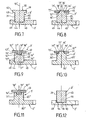
Les
La variante de réalisation illustrée à la
Dans la variante de réalisation illustrée à la
A titre de variante complémentaire, le logement 41" pourrait déboucher dans la paroi inférieure 21 de la pièce 40". A titre de variante complémentaire, la face latérale 31 ne prolonge pas nécessairement la paroi latérale 48" de la racine 46".As a further alternative, the
Dans la variante de réalisation illustrée à la
A titre de variante complémentaire, le logement 41"' pourrait déboucher dans la paroi supérieure 30 de la pièce 45"'. A titre de variante complémentaire, la face latérale 31 ne prolonge pas nécessairement la paroi latérale 48"' de la racine 46"'.As a further alternative, the
Les variantes de réalisation illustrées aux
La variante de réalisation illustrée à la
Les variantes de réalisation illustrées aux
Dans la variante de réalisation illustrée à la
A titre de variante complémentaire, le logement 71' ne traverse pas nécessairement la pièce 70'. Egalement à titre de variante complémentaire, la pièce 70' peut former une partie du montant 65. Egalement à titre de variante complémentaire, la pièce 70' n'est pas nécessairement réalisée à partir de poudre de matériau magnétique compactée, mais peut par exemple être réalisée à partir d'un empilage de tôles magnétiques.As a complementary alternative, the housing 71 'does not necessarily cross the part 70'. Also as a complementary variant, the part 70 'can form a part of the
La variante de réalisation illustrée à la
A titre de variante complémentaire, le logement 71" peut traverser la pièce 75". Egalement à titre de variante complémentaire, la pièce 70" peut former une partie du montant 65. Egalement à titre de variante complémentaire, la pièce 75" n'est pas nécessairement réalisée à partir de poudre de matériau magnétique compactée, mais peut par exemple être réalisée à partir d'un empilage de tôles magnétiques.As a further alternative, the
Les variantes de réalisation illustrées aux
La variante de réalisation illustrée à la
A titre de variante complémentaire, le logement 71'" ne traverse pas nécessairement la pièce 70"'. Egalement à titre de variante complémentaire, la pièce 70"' n'est pas nécessairement réalisée à partir d'un empilage de tôles magnétiques, mais peut par exemple être réalisée à partir de poudre de matériau magnétique compactée.As a further alternative, the housing 71 '"does not necessarily cross the
La variante de réalisation illustrée à la
La variante de réalisation illustrée à la
A titre de variante complémentaire, les logements 91 ne traversent pas nécessairement la pièce 90. Egalement à titre de variante complémentaire, la racine 46' ne prolonge pas nécessairement la paroi latérale 31. Egalement à titre de variante complémentaire, la base 2' peut comporter ou être formée par plusieurs pièces obtenues à partir d'un empilage de tôles magnétiques. Egalement à titre de variante complémentaire une ou plusieurs des pièces 45' formant l'un des noyaux peut former également une partie de la base 2'.As a complementary variant, the housings 91 do not necessarily pass through the
Dans le deuxième exemple de réalisation et ses différentes variantes, les surfaces d'emboîtement sont dépourvues d'arête et sont définies par une génératrice parallèle à la direction axiale 10'. Les pièces 40, 40', 40", 40"', 60, 70', 75', 70", 75", 80', 80" sont réalisées à partir de poudre de matériau magnétique compactée et constituent au moins partiellement les noyaux 3'. Les pièces 40, 40', 40", 40"', 60 constituent entièrement les noyaux 3'.In the second embodiment and its various variants, the interlocking surfaces are devoid of edges and are defined by a generatrix parallel to the axial direction 10 '.
A titre de variante pour le deuxième exemple de réalisation, la base 2' du stator peut être réalisée en plusieurs pièces, notamment en plusieurs pièces obtenues par compactage de poudre de matériau magnétique.As a variant for the second exemplary embodiment, the base 2 'of the stator can be made in several parts, in particular in several parts obtained by compaction of powder of magnetic material.
L'emboîtement entre les pièces de la base 2' peut notamment être conforme à l'emboîtement des pièces 11, 12, 13 de la base 2 du premier exemple de réalisation. D'autres emboîtements sont toutefois envisageables, tels qu'une pièce 101 entourant une pièce 100, comme illustré par exemple sur la
La
La
La
A titre de variante pour le premier ou le deuxième exemple de réalisation, les surfaces d'emboîtement 16, 17 ; 102, 103 ne sont pas nécessairement ménagées uniquement dans la base 2, 2'. Les surfaces d'emboîtement 16, 17 ; 102, 103 peuvent par exemple traverser au moins l'un des noyaux 3, 3'.As a variant for the first or second embodiment, the engagement surfaces 16, 17; 102, 103 are not necessarily provided solely in the
A titre de variante additionnelle pour l'un ou l'autre des exemples de réalisation, les surfaces d'emboîtement peuvent comporter une ou plusieurs arêtes. Egalement à titre de variante additionnelle pour l'un ou l'autre des exemples de réalisation les surfaces d'emboîtement ne sont pas nécessairement définies par une génératrice parallèle à la direction axiale, mais peuvent notamment être tronconiques.As an additional variant for one or other of the exemplary embodiments, the interlocking surfaces may comprise one or more edges. Also as an additional variant for one or the other of the embodiments, the interlocking surfaces are not necessarily defined by a generatrix parallel to the axial direction, but may in particular be frustoconical.
A titre de variante additionnelle pour l'un ou l'autre des exemples de réalisation, la base 2, 2' du stator 1 ne comporte pas nécessairement de passage 20, 20'. Le nombre de pôles du stator 1 n'est pas nécessairement de neuf ; le nombre de pôles du rotor 5 n'est pas nécessairement de six. L'alimentation du moteur n'est pas nécessairement triphasée.As an additional variant for one or other of the exemplary embodiments, the
A titre de variante additionnelle pour l'un ou l'autre des exemples de réalisation les surfaces d'emboîtement peuvent comporter plusieurs parties saillantes et/ou plusieurs parties rentrantes.As an additional variant for one or other of the exemplary embodiments, the interlocking surfaces may comprise several projecting parts and / or several reentrant parts.
Les différents exemples et variantes de réalisation décrits peuvent être combinés entre eux.The various examples and embodiments described can be combined with one another.
La présente invention n'est nullement limitée aux exemples de réalisation décrits et à leurs variantes, mais englobe de nombreuses modifications dans le cadre des revendications.The present invention is in no way limited to the described exemplary embodiments and their variants, but encompasses many modifications within the scope of the claims.
Claims (20)
- A stator for an axial flux electric motor, the stator being made at least in part out of a compacted powder of magnetic material, and comprising cores (3; 3') projecting in an axial direction (10; 10') from a base (2; 2'), the cores (3; 3') being arranged circularly on the base (2; 2'), each core (3; 3') being designed to receive a coil (4), said stator being made up of assembled-together parts (11, 12, 13; 100, 101; 100', 101; 100", 101) having engagement surfaces (16, 17; 44, 49; 44', 49'; 44"; 49"; 44"', 49"'; 74', 79'; 74", 79"; 94, 49'; 102, 103), some of the parts (11, 12, 13; 100; 100'; 100") constituting at least portions of said cores (3; 3') being made from a compacted powder of magnetic material, the stator being characterized in that the base (2; 2') is made up of a plurality of assembled-together parts (11, 12, 13; 100, 101; 100', 101; 100", 101) including at least some engagement surfaces (16, 17; 102, 103), and in that around the cores (3; 3'), the base (2; 2') is made from a compacted powder of magnetic material.
- A stator according to claim 1, characterized in that the base (2; 2') is annular.
- A stator according to claim 2, characterized in that the engagement surfaces (16, 17) of the parts (11, 12, 13) cut through the annular base (2; 2').
- A stator according to any one of claims 1 to 3, characterized in that the base (2, 2') is made up of an assembly of a plurality of parts (11, 12, 13; 100, 101; 100', 101) made from a compacted powder of magnetic material and including at least some of the engagement surfaces (16, 17; 102, 103).
- A stator according to claim 4, characterized in that at least one of the parts (45; 45'; 45") constituting at least a portion of one of the cores (3') includes a root (46; 46'; 46") or respectively a housing (41 "') that is mounted in a housing (41; 41', 41 ") or respectively on a root (46"') formed in or on the or one of the parts (40; 40'; 40"; 40"') constituting the base (2'), the engagement surfaces (44, 49, 44', 49'; 44", 49"; 44"'; 49"') being formed respectively on a side wall (48; 48'; 48"; 48"') of the root and by a side wall (43; 43'; 43"; 43"') of the housing.
- A stator according to claim 5, characterized in that at least one of the cores (3') presents a side wall (31) extending the side wall (48; 48') forming the engagement surface (49; 49') of the root (46; 46').
- A stator according to claim 5 or claim 6, characterized in that at least one of the housings (41') passes through the or one of the parts (40') constituting at least a portion of the base (2').
- A stator according to any one of claims 1 to 3, characterized in that the base (2; 2') is made of a plurality of assembled-together parts (11, 12, 13; 100, 101; 100', 101; 100", 101) including some of the engagement surfaces (16, 17; 102, 103), and in that the parts (11, 12, 13; 100; 100';100") constituting at least a portion of said cores (3; 3') include a portion of the base (2; 2').
- A stator according to claim 8, characterized in that the parts (11, 12, 13; 100; 100'; 100") constituting at least a portion of said cores (3; 3') extend around said cores (3; 3') to form a portion of the base (2; 2').
- A stator according to claim 8 or claim 9, characterized in that the base (2') includes a part (101) made from a stack of magnetic laminations without any core-forming uprights.
- A stator according to any one of claims 1 to 10, characterized in that the engagement surfaces (16, 17; 44, 49; 44', 49'; 44", 49"; 44"', 49"', 74', 79'; 74", 79"; 94, 49'; 102, 103) are defined by generator lines extending parallel to the axial direction (10; 10').
- A stator according to any one of claims 1 to 11, characterized in that the engagement surfaces (16, 17; 44, 49; 44', 49'; 44", 49"; 44"', 49"', 74', 79'; 74", 79", 94, 49'; 102, 103) do not include any edges.
- A stator according to any one of claims 1 to 12, characterized in that each core (3; 3') is formed by one or more parts (11, 12, 13; 45; 45'; 45"; 45"'; 60; 70', 75'; 70", 75"; 70", 80", 100; 100'; 100") made from a compacted powder of magnetic material.
- A stator according to any one of claims 1 to 13, characterized in that at least two of the parts (11, 12, 13; 80'; 80"; 100; 100'; 100") constituting at least a portion of one of the cores (3; 3') also constitute a portion of the base (2; 2').
- A stator according to claim 14, characterized in that the engagement surfaces (16, 17; 102, 103) of said parts (11, 12, 13; 100, 101; 100', 101; 100", 101) are formed in the base (2; 2').
- A stator according to any one of claims 1 to 15, characterized in that at least one of the cores (3') presents an upright (65; 65'; 65") surmounted by a cap (61).
- A stator according to claim 16, characterized in that at least one of the parts (75'; 75'; 80'; 80") constituting a portion of one of the cores (3') includes a tenon (76') or respectively a housing (71") mounted in a housing (71') or respectively on a tenon (76") formed on or in another one of the parts (70'; 70"; 70"') constituting a portion of said core (3'), the engagement surfaces (74', 79'; 74"; 79") being formed respectively by a side wall (78'; 78") of the tenon and by a side wall (73'; 73") of the housing.
- A stator according to any one of claims 1 to 17, characterized in that the or one of the parts (11, 12, 13; 80'; 80"; 100; 100'; 100") constituting at least a portion of the upright (65'; 65") of one of the cores (3; 3') also constitutes at least a portion of the base (2; 2').
- A stator according to any one of claims 1 to 18, characterized in that it includes at least two identical parts (11, 12, 13; 45; 45'; 45"; 45"'; 60; 70'; 70"; 70"'; 75'; 75") made from a compacted powder of magnetic material.
- A stator according to any one of claims 1 to 19, characterized in that at least one of the parts (11, 12, 13; 80'; 80"; 100; 101'; 100") constituting at least a portion of one of the cores (3; 3') also constitutes a portion of the base (2; 2').
Applications Claiming Priority (3)
| Application Number | Priority Date | Filing Date | Title |
|---|---|---|---|
| FR0301659 | 2003-02-12 | ||
| FR0301659A FR2851088B1 (en) | 2003-02-12 | 2003-02-12 | STATOR FOR ELECTRIC MOTOR WITH AXIAL FLUX |
| PCT/FR2004/000290 WO2004075376A2 (en) | 2003-02-12 | 2004-02-09 | Stator for axial flux electric motor |
Publications (2)
| Publication Number | Publication Date |
|---|---|
| EP1593190A2 EP1593190A2 (en) | 2005-11-09 |
| EP1593190B1 true EP1593190B1 (en) | 2008-07-16 |
Family
ID=32731974
Family Applications (1)
| Application Number | Title | Priority Date | Filing Date |
|---|---|---|---|
| EP04709253A Expired - Lifetime EP1593190B1 (en) | 2003-02-12 | 2004-02-09 | Stator for axial flux electric motor |
Country Status (6)
| Country | Link |
|---|---|
| EP (1) | EP1593190B1 (en) |
| AT (1) | ATE401690T1 (en) |
| DE (1) | DE602004015077D1 (en) |
| ES (1) | ES2309497T3 (en) |
| FR (1) | FR2851088B1 (en) |
| WO (1) | WO2004075376A2 (en) |
Cited By (3)
| Publication number | Priority date | Publication date | Assignee | Title |
|---|---|---|---|---|
| WO2018162072A1 (en) * | 2017-03-10 | 2018-09-13 | Arcelik Anonim Sirketi | Permanent magnet axial-flux electric machine with auxiliary winding arrangement |
| US20210167641A1 (en) * | 2018-07-27 | 2021-06-03 | Sumitomo Electric Industries, Ltd. | Core, stator, and rotating electrical machine |
| US11804763B2 (en) * | 2019-09-20 | 2023-10-31 | Seiko Epson Corporation | Axial gap motor |
Families Citing this family (8)
| Publication number | Priority date | Publication date | Assignee | Title |
|---|---|---|---|---|
| JP2006050745A (en) * | 2004-08-03 | 2006-02-16 | Nissan Motor Co Ltd | Axial gap rotary electric machine |
| US8283832B2 (en) * | 2004-10-25 | 2012-10-09 | Novatorque, Inc. | Sculpted field pole members and methods of forming the same for electrodynamic machines |
| JP4716060B2 (en) * | 2009-11-30 | 2011-07-06 | 株式会社富士通ゼネラル | Axial gap type electric motor and pump device |
| GB201301305D0 (en) * | 2013-01-24 | 2013-03-06 | Gkn Evo Edrive Systems Ltd | Electrical machines |
| DE102014203945A1 (en) * | 2014-03-05 | 2015-09-10 | Robert Bosch Gmbh | Stator element for constructing a stator assembly for an electrical machine, stator assembly and method for constructing a stator assembly |
| DE102015223766A1 (en) | 2015-11-30 | 2017-06-01 | Baumüller Nürnberg GmbH | Electric machine |
| WO2018162073A1 (en) | 2017-03-10 | 2018-09-13 | Arcelik Anonim Sirketi | Permanent magnet axial-flux electric machine stator and rotor assemblies |
| DE102017204401A1 (en) * | 2017-03-16 | 2018-09-20 | Brose Fahrzeugteile GmbH & Co. Kommanditgesellschaft, Würzburg | Segmented stator for one or in an axial flow machine |
Family Cites Families (4)
| Publication number | Priority date | Publication date | Assignee | Title |
|---|---|---|---|---|
| JPH10145990A (en) * | 1996-11-14 | 1998-05-29 | Meidensha Corp | Stator iron core of outer rotor motor |
| US6445105B1 (en) * | 1999-04-06 | 2002-09-03 | General Electric Company | Axial flux machine and method of fabrication |
| JP2001037107A (en) * | 1999-07-23 | 2001-02-09 | Hitachi Ferrite Electronics Ltd | Yoke for motor |
| DE10048492A1 (en) * | 2000-09-29 | 2002-04-11 | Linde Ag | Stator for axial field electrical machine, has stator coils positioned between radial spokes projecting inwards from stator ring |
-
2003
- 2003-02-12 FR FR0301659A patent/FR2851088B1/en not_active Expired - Fee Related
-
2004
- 2004-02-09 WO PCT/FR2004/000290 patent/WO2004075376A2/en active IP Right Grant
- 2004-02-09 EP EP04709253A patent/EP1593190B1/en not_active Expired - Lifetime
- 2004-02-09 AT AT04709253T patent/ATE401690T1/en not_active IP Right Cessation
- 2004-02-09 DE DE602004015077T patent/DE602004015077D1/en not_active Expired - Lifetime
- 2004-02-09 ES ES04709253T patent/ES2309497T3/en not_active Expired - Lifetime
Cited By (4)
| Publication number | Priority date | Publication date | Assignee | Title |
|---|---|---|---|---|
| WO2018162072A1 (en) * | 2017-03-10 | 2018-09-13 | Arcelik Anonim Sirketi | Permanent magnet axial-flux electric machine with auxiliary winding arrangement |
| US20210167641A1 (en) * | 2018-07-27 | 2021-06-03 | Sumitomo Electric Industries, Ltd. | Core, stator, and rotating electrical machine |
| US11770034B2 (en) * | 2018-07-27 | 2023-09-26 | Sumitomo Electric Industries, Ltd. | Core for, rotating electrical machine |
| US11804763B2 (en) * | 2019-09-20 | 2023-10-31 | Seiko Epson Corporation | Axial gap motor |
Also Published As
| Publication number | Publication date |
|---|---|
| FR2851088B1 (en) | 2006-01-27 |
| FR2851088A1 (en) | 2004-08-13 |
| EP1593190A2 (en) | 2005-11-09 |
| DE602004015077D1 (en) | 2008-08-28 |
| ES2309497T3 (en) | 2008-12-16 |
| ATE401690T1 (en) | 2008-08-15 |
| WO2004075376A3 (en) | 2005-01-06 |
| WO2004075376A2 (en) | 2004-09-02 |
Similar Documents
| Publication | Publication Date | Title |
|---|---|---|
| EP1593190B1 (en) | Stator for axial flux electric motor | |
| US6675460B2 (en) | Method of making a powder metal rotor for a synchronous reluctance machine | |
| EP3827500B1 (en) | Asymmetric poles of a rotor of an electrical machine | |
| CA3011515A1 (en) | Stator for electromagnetic machine with axial flow with unitary portions forming a stator ring | |
| CN206820570U (en) | Rotor assembly | |
| JP4856999B2 (en) | motor | |
| EP3027854A1 (en) | Turbine engine casing and manufacturing method | |
| CA2847102A1 (en) | Cover for connecting energy storage assemblies | |
| EP3522334A1 (en) | Magnetic circuit for element of a rotating electric machine, associated method and electric machine | |
| FR2533365A1 (en) | METHOD FOR PRODUCING ANNULAR CORES FOR DEVIATION UNITS, AND CERAMIC SUPPORT FOR USE THEREIN | |
| FR3071370B1 (en) | ISTHMA OF MAGNETIC BRIDGES OF AN ELECTRIC MACHINE ROTOR | |
| EP1215943B1 (en) | Microwave oven | |
| EP1388196A1 (en) | Electric motor for food processing electrical household appliance | |
| EP3198617B1 (en) | Magnetic core of rotating transformer | |
| EP2878071A1 (en) | Winding for a stator element of a permanent-magnet motor or generator, comprising at least one single-component, rigid limb, and method for producing same | |
| WO2022112704A1 (en) | Flange and rotor for a rotary electrical machine | |
| FR3061370A1 (en) | ELECTROMAGNETIC ASSEMBLY WITH POLYPHASE STRUCTURE | |
| EP1506607A1 (en) | Electric motor for household electrical food processor | |
| FR2946811A1 (en) | Stator for electric generator of axial flow wind turbine i.e. synchronous/asynchronous induction machine, has contact surfaces arranged in transverse way to magnetic field lines created in disk during operation of electric generator | |
| WO2014136042A2 (en) | Electric machine having a coupling flange | |
| FR2757703A1 (en) | Electrical motor rotor for cars | |
| CN205113945U (en) | Multifunctional article storing box | |
| EP1564873A1 (en) | Electric synchronous motor | |
| JP2005020815A (en) | Armature core of motor | |
| FR2968481A1 (en) | Rotating alternating-current machine e.g. tetra-polar induction motor, has magnetic yoke comprising variable section in axial plane of machine and formed by assembling small unitary elements made of ferromagnetic material |
Legal Events
| Date | Code | Title | Description |
|---|---|---|---|
| PUAI | Public reference made under article 153(3) epc to a published international application that has entered the european phase |
Free format text: ORIGINAL CODE: 0009012 |
|
| 17P | Request for examination filed |
Effective date: 20050808 |
|
| AK | Designated contracting states |
Kind code of ref document: A2 Designated state(s): AT BE BG CH CY CZ DE DK EE ES FI FR GB GR HU IE IT LI LU MC NL PT RO SE SI SK TR |
|
| AX | Request for extension of the european patent |
Extension state: AL LT LV MK |
|
| DAX | Request for extension of the european patent (deleted) | ||
| GRAP | Despatch of communication of intention to grant a patent |
Free format text: ORIGINAL CODE: EPIDOSNIGR1 |
|
| GRAS | Grant fee paid |
Free format text: ORIGINAL CODE: EPIDOSNIGR3 |
|
| GRAA | (expected) grant |
Free format text: ORIGINAL CODE: 0009210 |
|
| AK | Designated contracting states |
Kind code of ref document: B1 Designated state(s): AT BE BG CH CY CZ DE DK EE ES FI FR GB GR HU IE IT LI LU MC NL PT RO SE SI SK TR |
|
| REG | Reference to a national code |
Ref country code: GB Ref legal event code: FG4D Free format text: NOT ENGLISH |
|
| REG | Reference to a national code |
Ref country code: CH Ref legal event code: EP |
|
| REF | Corresponds to: |
Ref document number: 602004015077 Country of ref document: DE Date of ref document: 20080828 Kind code of ref document: P |
|
| REG | Reference to a national code |
Ref country code: IE Ref legal event code: FG4D Free format text: LANGUAGE OF EP DOCUMENT: FRENCH |
|
| REG | Reference to a national code |
Ref country code: ES Ref legal event code: FG2A Ref document number: 2309497 Country of ref document: ES Kind code of ref document: T3 |
|
| PG25 | Lapsed in a contracting state [announced via postgrant information from national office to epo] |
Ref country code: PT Free format text: LAPSE BECAUSE OF FAILURE TO SUBMIT A TRANSLATION OF THE DESCRIPTION OR TO PAY THE FEE WITHIN THE PRESCRIBED TIME-LIMIT Effective date: 20081216 |
|
| PG25 | Lapsed in a contracting state [announced via postgrant information from national office to epo] |
Ref country code: FI Free format text: LAPSE BECAUSE OF FAILURE TO SUBMIT A TRANSLATION OF THE DESCRIPTION OR TO PAY THE FEE WITHIN THE PRESCRIBED TIME-LIMIT Effective date: 20080716 Ref country code: BG Free format text: LAPSE BECAUSE OF FAILURE TO SUBMIT A TRANSLATION OF THE DESCRIPTION OR TO PAY THE FEE WITHIN THE PRESCRIBED TIME-LIMIT Effective date: 20081016 Ref country code: AT Free format text: LAPSE BECAUSE OF FAILURE TO SUBMIT A TRANSLATION OF THE DESCRIPTION OR TO PAY THE FEE WITHIN THE PRESCRIBED TIME-LIMIT Effective date: 20080716 Ref country code: SI Free format text: LAPSE BECAUSE OF FAILURE TO SUBMIT A TRANSLATION OF THE DESCRIPTION OR TO PAY THE FEE WITHIN THE PRESCRIBED TIME-LIMIT Effective date: 20080716 |
|
| REG | Reference to a national code |
Ref country code: IE Ref legal event code: FD4D |
|
| PG25 | Lapsed in a contracting state [announced via postgrant information from national office to epo] |
Ref country code: EE Free format text: LAPSE BECAUSE OF FAILURE TO SUBMIT A TRANSLATION OF THE DESCRIPTION OR TO PAY THE FEE WITHIN THE PRESCRIBED TIME-LIMIT Effective date: 20080716 Ref country code: DK Free format text: LAPSE BECAUSE OF FAILURE TO SUBMIT A TRANSLATION OF THE DESCRIPTION OR TO PAY THE FEE WITHIN THE PRESCRIBED TIME-LIMIT Effective date: 20080716 Ref country code: IE Free format text: LAPSE BECAUSE OF FAILURE TO SUBMIT A TRANSLATION OF THE DESCRIPTION OR TO PAY THE FEE WITHIN THE PRESCRIBED TIME-LIMIT Effective date: 20080716 |
|
| PLBE | No opposition filed within time limit |
Free format text: ORIGINAL CODE: 0009261 |
|
| STAA | Information on the status of an ep patent application or granted ep patent |
Free format text: STATUS: NO OPPOSITION FILED WITHIN TIME LIMIT |
|
| PG25 | Lapsed in a contracting state [announced via postgrant information from national office to epo] |
Ref country code: SK Free format text: LAPSE BECAUSE OF FAILURE TO SUBMIT A TRANSLATION OF THE DESCRIPTION OR TO PAY THE FEE WITHIN THE PRESCRIBED TIME-LIMIT Effective date: 20080716 Ref country code: CZ Free format text: LAPSE BECAUSE OF FAILURE TO SUBMIT A TRANSLATION OF THE DESCRIPTION OR TO PAY THE FEE WITHIN THE PRESCRIBED TIME-LIMIT Effective date: 20080716 Ref country code: RO Free format text: LAPSE BECAUSE OF FAILURE TO SUBMIT A TRANSLATION OF THE DESCRIPTION OR TO PAY THE FEE WITHIN THE PRESCRIBED TIME-LIMIT Effective date: 20080716 |
|
| 26N | No opposition filed |
Effective date: 20090417 |
|
| BERE | Be: lapsed |
Owner name: SEB S.A. Effective date: 20090228 |
|
| PG25 | Lapsed in a contracting state [announced via postgrant information from national office to epo] |
Ref country code: MC Free format text: LAPSE BECAUSE OF NON-PAYMENT OF DUE FEES Effective date: 20090228 |
|
| REG | Reference to a national code |
Ref country code: CH Ref legal event code: PL |
|
| PG25 | Lapsed in a contracting state [announced via postgrant information from national office to epo] |
Ref country code: CH Free format text: LAPSE BECAUSE OF NON-PAYMENT OF DUE FEES Effective date: 20090228 Ref country code: LI Free format text: LAPSE BECAUSE OF NON-PAYMENT OF DUE FEES Effective date: 20090228 |
|
| PG25 | Lapsed in a contracting state [announced via postgrant information from national office to epo] |
Ref country code: SE Free format text: LAPSE BECAUSE OF FAILURE TO SUBMIT A TRANSLATION OF THE DESCRIPTION OR TO PAY THE FEE WITHIN THE PRESCRIBED TIME-LIMIT Effective date: 20081016 |
|
| PG25 | Lapsed in a contracting state [announced via postgrant information from national office to epo] |
Ref country code: BE Free format text: LAPSE BECAUSE OF NON-PAYMENT OF DUE FEES Effective date: 20090228 |
|
| PG25 | Lapsed in a contracting state [announced via postgrant information from national office to epo] |
Ref country code: GR Free format text: LAPSE BECAUSE OF FAILURE TO SUBMIT A TRANSLATION OF THE DESCRIPTION OR TO PAY THE FEE WITHIN THE PRESCRIBED TIME-LIMIT Effective date: 20081017 |
|
| PG25 | Lapsed in a contracting state [announced via postgrant information from national office to epo] |
Ref country code: LU Free format text: LAPSE BECAUSE OF NON-PAYMENT OF DUE FEES Effective date: 20090209 |
|
| PG25 | Lapsed in a contracting state [announced via postgrant information from national office to epo] |
Ref country code: HU Free format text: LAPSE BECAUSE OF FAILURE TO SUBMIT A TRANSLATION OF THE DESCRIPTION OR TO PAY THE FEE WITHIN THE PRESCRIBED TIME-LIMIT Effective date: 20090117 |
|
| PG25 | Lapsed in a contracting state [announced via postgrant information from national office to epo] |
Ref country code: TR Free format text: LAPSE BECAUSE OF FAILURE TO SUBMIT A TRANSLATION OF THE DESCRIPTION OR TO PAY THE FEE WITHIN THE PRESCRIBED TIME-LIMIT Effective date: 20080716 |
|
| PG25 | Lapsed in a contracting state [announced via postgrant information from national office to epo] |
Ref country code: CY Free format text: LAPSE BECAUSE OF FAILURE TO SUBMIT A TRANSLATION OF THE DESCRIPTION OR TO PAY THE FEE WITHIN THE PRESCRIBED TIME-LIMIT Effective date: 20080716 |
|
| PGFP | Annual fee paid to national office [announced via postgrant information from national office to epo] |
Ref country code: NL Payment date: 20150114 Year of fee payment: 12 |
|
| PGFP | Annual fee paid to national office [announced via postgrant information from national office to epo] |
Ref country code: ES Payment date: 20150220 Year of fee payment: 12 Ref country code: IT Payment date: 20150225 Year of fee payment: 12 |
|
| REG | Reference to a national code |
Ref country code: FR Ref legal event code: PLFP Year of fee payment: 13 |
|
| REG | Reference to a national code |
Ref country code: NL Ref legal event code: MM Effective date: 20160301 |
|
| PG25 | Lapsed in a contracting state [announced via postgrant information from national office to epo] |
Ref country code: IT Free format text: LAPSE BECAUSE OF NON-PAYMENT OF DUE FEES Effective date: 20160209 |
|
| PG25 | Lapsed in a contracting state [announced via postgrant information from national office to epo] |
Ref country code: NL Free format text: LAPSE BECAUSE OF NON-PAYMENT OF DUE FEES Effective date: 20160301 |
|
| REG | Reference to a national code |
Ref country code: FR Ref legal event code: PLFP Year of fee payment: 14 |
|
| REG | Reference to a national code |
Ref country code: FR Ref legal event code: CA Effective date: 20170322 |
|
| PG25 | Lapsed in a contracting state [announced via postgrant information from national office to epo] |
Ref country code: ES Free format text: LAPSE BECAUSE OF NON-PAYMENT OF DUE FEES Effective date: 20160210 |
|
| REG | Reference to a national code |
Ref country code: FR Ref legal event code: PLFP Year of fee payment: 15 |
|
| PGFP | Annual fee paid to national office [announced via postgrant information from national office to epo] |
Ref country code: DE Payment date: 20190211 Year of fee payment: 16 Ref country code: GB Payment date: 20190215 Year of fee payment: 16 |
|
| PGFP | Annual fee paid to national office [announced via postgrant information from national office to epo] |
Ref country code: FR Payment date: 20190228 Year of fee payment: 16 |
|
| REG | Reference to a national code |
Ref country code: DE Ref legal event code: R119 Ref document number: 602004015077 Country of ref document: DE |
|
| GBPC | Gb: european patent ceased through non-payment of renewal fee |
Effective date: 20200209 |
|
| PG25 | Lapsed in a contracting state [announced via postgrant information from national office to epo] |
Ref country code: FR Free format text: LAPSE BECAUSE OF NON-PAYMENT OF DUE FEES Effective date: 20200229 Ref country code: GB Free format text: LAPSE BECAUSE OF NON-PAYMENT OF DUE FEES Effective date: 20200209 Ref country code: DE Free format text: LAPSE BECAUSE OF NON-PAYMENT OF DUE FEES Effective date: 20200901 |