EP1592606B1 - Cabine a poste de conduite pour vehicule a moteur - Google Patents
Cabine a poste de conduite pour vehicule a moteur Download PDFInfo
- Publication number
- EP1592606B1 EP1592606B1 EP04707536A EP04707536A EP1592606B1 EP 1592606 B1 EP1592606 B1 EP 1592606B1 EP 04707536 A EP04707536 A EP 04707536A EP 04707536 A EP04707536 A EP 04707536A EP 1592606 B1 EP1592606 B1 EP 1592606B1
- Authority
- EP
- European Patent Office
- Prior art keywords
- seat
- cab
- height
- cabin
- floor
- Prior art date
- Legal status (The legal status is an assumption and is not a legal conclusion. Google has not performed a legal analysis and makes no representation as to the accuracy of the status listed.)
- Expired - Lifetime
Links
- 239000011324 bead Substances 0.000 abstract description 2
- 238000001816 cooling Methods 0.000 description 7
- 230000001105 regulatory effect Effects 0.000 description 4
- 230000008901 benefit Effects 0.000 description 3
- 210000000689 upper leg Anatomy 0.000 description 3
- XQMVBICWFFHDNN-UHFFFAOYSA-N 5-amino-4-chloro-2-phenylpyridazin-3-one;(2-ethoxy-3,3-dimethyl-2h-1-benzofuran-5-yl) methanesulfonate Chemical compound O=C1C(Cl)=C(N)C=NN1C1=CC=CC=C1.C1=C(OS(C)(=O)=O)C=C2C(C)(C)C(OCC)OC2=C1 XQMVBICWFFHDNN-UHFFFAOYSA-N 0.000 description 2
- 230000033228 biological regulation Effects 0.000 description 2
- 230000008859 change Effects 0.000 description 2
- 210000003128 head Anatomy 0.000 description 2
- 230000006872 improvement Effects 0.000 description 2
- 210000003127 knee Anatomy 0.000 description 2
- 208000008035 Back Pain Diseases 0.000 description 1
- 208000008930 Low Back Pain Diseases 0.000 description 1
- 235000014676 Phragmites communis Nutrition 0.000 description 1
- 230000001133 acceleration Effects 0.000 description 1
- 230000005540 biological transmission Effects 0.000 description 1
- 238000006243 chemical reaction Methods 0.000 description 1
- 238000010276 construction Methods 0.000 description 1
- 230000004069 differentiation Effects 0.000 description 1
- 230000002349 favourable effect Effects 0.000 description 1
- 210000004744 fore-foot Anatomy 0.000 description 1
- 238000010438 heat treatment Methods 0.000 description 1
- 230000010354 integration Effects 0.000 description 1
- 230000007246 mechanism Effects 0.000 description 1
- 238000012986 modification Methods 0.000 description 1
- 230000004048 modification Effects 0.000 description 1
- 230000000877 morphologic effect Effects 0.000 description 1
- 208000001491 myopia Diseases 0.000 description 1
- 230000001144 postural effect Effects 0.000 description 1
- 230000007425 progressive decline Effects 0.000 description 1
- 230000004044 response Effects 0.000 description 1
Images
Classifications
-
- B—PERFORMING OPERATIONS; TRANSPORTING
- B62—LAND VEHICLES FOR TRAVELLING OTHERWISE THAN ON RAILS
- B62D—MOTOR VEHICLES; TRAILERS
- B62D33/00—Superstructures for load-carrying vehicles
- B62D33/06—Drivers' cabs
-
- B—PERFORMING OPERATIONS; TRANSPORTING
- B60—VEHICLES IN GENERAL
- B60N—SEATS SPECIALLY ADAPTED FOR VEHICLES; VEHICLE PASSENGER ACCOMMODATION NOT OTHERWISE PROVIDED FOR
- B60N2/00—Seats specially adapted for vehicles; Arrangement or mounting of seats in vehicles
- B60N2/02—Seats specially adapted for vehicles; Arrangement or mounting of seats in vehicles the seat or part thereof being movable, e.g. adjustable
- B60N2/04—Seats specially adapted for vehicles; Arrangement or mounting of seats in vehicles the seat or part thereof being movable, e.g. adjustable the whole seat being movable
- B60N2/10—Seats specially adapted for vehicles; Arrangement or mounting of seats in vehicles the seat or part thereof being movable, e.g. adjustable the whole seat being movable tiltable
-
- B—PERFORMING OPERATIONS; TRANSPORTING
- B60—VEHICLES IN GENERAL
- B60N—SEATS SPECIALLY ADAPTED FOR VEHICLES; VEHICLE PASSENGER ACCOMMODATION NOT OTHERWISE PROVIDED FOR
- B60N2/00—Seats specially adapted for vehicles; Arrangement or mounting of seats in vehicles
- B60N2/02—Seats specially adapted for vehicles; Arrangement or mounting of seats in vehicles the seat or part thereof being movable, e.g. adjustable
- B60N2/04—Seats specially adapted for vehicles; Arrangement or mounting of seats in vehicles the seat or part thereof being movable, e.g. adjustable the whole seat being movable
- B60N2/16—Seats specially adapted for vehicles; Arrangement or mounting of seats in vehicles the seat or part thereof being movable, e.g. adjustable the whole seat being movable height-adjustable
Definitions
- the present invention relates to a cabin incorporating a driving position. It also relates to a motor vehicle comprising such a cabin. The invention relates to a new driving position and its integration into the particular architecture of industrial vehicles.
- the length of the cab of a truck traveling in Europe may not exceed a value of 2.3 m for road purposes.
- the advantage of the height of the driving position is that visibility of the road is favored.
- the disadvantage of such an architecture is that the height at which the cabin is located becomes important. In this case, access to the driving position is binding.
- the cabin is positioned in the extension of the engine and in a much more remote position, called “rear engine cabin”. This reduces the height of the floor.
- the cab is generally 200 mm to 300 mm lower compared to the cabs of trucks circulating in Europe.
- a driving position with a standard driving position is characterized by large angles of visibility from the front to the bottom and high seat height, defined in relation to the floor of the cabin.
- the height of the driver's seat of industrial vehicles is generally adjustable and between 400 mm and 550 nun from the floor of the cabin. This allows European drivers to benefit from frontal visibility between 20 ° and 30 ° and American drivers between 12 ° and 20 °.
- the position of the seat cushion is not optimized for drivers on long journeys, fatigue being a source of stress.
- traditional seats cause back pain. Indeed, in traditional seats, the driving positions are very straight, causing lower back pain due to the progressive decline of the lumbar curvature.
- the pressures on the seat are also stronger than in a lightweight vehicle seat, such as those described by "ATD Positioning based on driver posture and position", MANARY, Reed and Al., SAE TECHNICAL PAPERS, ISSN 0148 ⁇ 7191 and the preamble of claim 1, the pressure is less well distributed between the seat and the backrest as it can be commonly between a chair and an armchair.
- a first object of the invention is to design a cabin having a driving position having a comfortable driving position, good visibility and easy access.
- a second object of the invention is to develop a cabin whose seat ergonomics allows the driver to drive without fatigue, with an optimal concentration throughout the journey.
- a third object of the invention is to provide a motor vehicle for example industrial equipped with a cabin whose ergonomics have been particularly studied for the driver to feel at ease.
- a cabin incorporating a driving position, intended for a motor vehicle comprises a driver's seat having a seat and a backrest, a steering member, at least one pedal control member, and a dashboard, the driver having a heel point.
- a manikin bearing the reference SAE Std J826 models the morphological characteristics of a driver installed at driving position and sitting on the seat. In all cases, for example at the time of delivery of the truck, the cabin is able to present the features of the invention, even when the driver or the mannequin SAE Std J826 are not sitting on the seat.
- a driver's stub point means a point at the rear end of the driver's stub and thus the SAE Std J826 manikin installed on the seat in contact with the floor, when the driver's forefoot and Same SAE Std J826 manikin is positioned on the pedal controller.
- Seat height means a height measured vertically between the hip point and the heel point of the SAE Std J826 manikin installed on the seat.
- Dashboard height means a height measured vertically between the heel point of the SAE Std J826 manikin installed on the seat and the top of the dashboard. This specific height may be provided at the level of the change of direction member or for the entire driving position.
- the seat back can have a rear angle of inclination very preferably substantially equal to 25 ° relative to the vertical.
- the seat may have a height, vertically, very preferably substantially equal to 350 mm with respect to the heel point.
- the dashboard may have a height, vertically, very preferably substantially equal to 550 mm from the heel point.
- Angle of inclination of the seat means either an angle measured between the upper surface of the seat and the horizontal, or a measured angle between the segment passing through the hip point and the knee point of the SAE Std manikin. J826 installed on the seat and horizontal.
- the seat cushion can be tilted towards the rear of the cabin.
- this seat can advantageously have an angle substantially between 10 ° and 20 ° relative to the horizontal. In the aforementioned range, this angle may be preferably substantially equal to 15 ° relative to the horizontal.
- the heel point can be elevated.
- the height of the heel point, vertically can be substantially between 50 mm and 200 mm by relative to the floor of the cabin.
- the height of the heel point, vertically may be substantially equal to 175 mm from the floor of the cabin.
- the driving position may advantageously comprise a second floor raised to a value corresponding to the height of the heel point.
- the second floor will have a height, vertically, substantially between 50 mm and 200 mm, and preferably substantially equal to 175 mm, relative to the first floor of the cabin.
- the latter can be pivotally mounted relative to the floor of the cabin.
- a motor vehicle is characterized in that it is equipped with a cabin as described above, integrating a driving position.
- An industrial vehicle (1) of the type circulating in Europe, comprises a chassis (2), wheels (3), a cabin (4), mechanical members including a motor (6) and a cooling unit (7).
- the vehicle (1) illustrated in FIG. Magnum® model of the Applicant.
- the cabin (4) is mounted above the two front wheels (3), the engine (6) and the cooling unit (7) in an advanced cabin architecture.
- the height (D1), taken vertically, between the floor (5) of the cabin (4) and the ground is substantially between 1400 mm and 1600 mm, the ground, the vehicle (1), the cabin (4) and the floor (5) being substantially horizontal.
- the angle ( ⁇ 1) corresponding to the frontal visibility of the driver is substantially between 20 ° and 30 °.
- An industrial vehicle (8) of the type circulating in the United States, comprises a frame (2), wheels (3), a cabin (4), mechanical members including a motor (6) and a cooling unit (7). ).
- the vehicle (8) shown in Figure 2, is a Vision® model from Mack.
- the cabin (4) is mounted above the two front wheels (3), the engine (6) and the cooling unit (7) in a rear cabin engine architecture.
- the height (D2), taken vertically, between the floor (5) of the cabin (4) and the ground is substantially between 1200 mm and 1400 mm, the ground, the vehicle (1), the cabin (4) and the floor (5) being substantially horizontal.
- a cover (9) covers the motor (6) and the cooling unit (7).
- the angle ( ⁇ 2) corresponding to the frontal visibility of the driver is substantially between 12 ° and 20 °. This viewing angle ( ⁇ 2) of the driver is slightly lower for vehicles of this type (8) circulating in the United States, due to the presence of this front cover (9).
- the cabin (4) comprises a traditional type of driving position (11), shown in Figure 3.
- the traditional driving position (11) comprises a seat (12) on which the driver sits.
- the driver is here shown very schematically with reference to the specific points of a mannequin (13) SAE standard Std J826, installed on the seat (12).
- the seat is in two parts, a seat (14) and a backrest (16).
- the driving position (11) also comprises a steering member, in the form of a steering wheel (17) and at least one pedal control member (18), in the form of a pedal, for example a pedal acceleration, braking, ...
- the driving position (11) comprises a dashboard (19). Under the dashboard (19) is fixed the transmission mechanism (21) of the pedal controller (18).
- a steering column (22) passes under the dashboard (19) and transmits the rotations of the steering wheel (17) to the wheels (3) in a manner known per se.
- the cabin (4) and the driving position (11) are delimited by the front windshield (23).
- the angle of vision ( ⁇ , ⁇ 1 and ⁇ 2) of the traditional driving position (11) is here defined between the horizontal direction (H) passing through the head (24) and more particularly by the eyes (26) of the manikin (13). ) and the downward direction (L) passing through the head (24) and more particularly by the eyes (26) of the manikin (13) and limited by the base (27) of the windshield (23) and / or by the dashboard (19).
- the height (X) of the dashboard (19), which is defined vertically between the upper surface of the dashboard (19) and the floor (5) of the cabin (4) in the seat axis (12) is between 735 mm and 845 mm, the cabins (4) and the floor (5) being substantially horizontal.
- the seat (12) of the driving position (11) has a seat (14) substantially horizontal.
- this seat (14) thus has an upper surface which is substantially horizontal.
- the SAE Std J826 manikin (13) installed on the seat will have its femur (15) positioned horizontally.
- This seat (14) is at a height determined relative to the floor (5) which is adjustable. This height is such that the hip point and / or femur (15) of the SAE Std J826 dummy (13) installed on the seat is at a vertical height (Z) of between 400 mm and 550 mm. relative to the floor (5), the latter being substantially horizontal.
- the angle ( ⁇ ) of the backrest (16) is adjustable and varies between 0 ° and 25 ° relative to the vertical (V). The value used by the drivers is on average 15 ° relative to the vertical (V).
- the seat back (32) (31) is inclined towards the rear of the cabin ( 4).
- the angle of inclination ( ⁇ ) of the backrest (32) is adjustable and varies between 18 ° and 30 ° relative to the vertical (V).
- a value of the angle ( ⁇ ) may be 25 °.
- the comfort of the seat (31) is significantly increased.
- the seat (29) of the seat (31) is also inclined towards the rear of the cabin (4) at an angle ( ⁇ ).
- the angle of inclination ( ⁇ ) is here defined with respect to the inclination of the femur (15), that is to say of the line segment passing through the hip point (33) and the knee point (34) the SAE Std J826 (13) manikin installed on the seat (31), with respect to the horizontal, or with respect to the floor (5) of the cabin (4).
- the seat (29) thus has an angle ( ⁇ ) of between 10 ° and 20 °.
- a value of the angle ( ⁇ ) may be 15 °.
- the height (Z1) of the seat (31) is set vertically between the hip point (33) of the SAE Std J826 manikin (13) installed on the seat (31) and the heel point (36) of the SAE Std J826 manikin ( 13).
- the height (Z1) of the seat (31) thus varies between 300 mm and 400 mm with respect to this bead point (36).
- the most preferred driving positions of the drivers are such that their hip is at a height (Z1) close to 300 mm, and no longer at a height (Z) having values of 400 mm to 550 mm in the cabins of the type traditional (4).
- the height (X1) of the dashboard (19) is between 500 mm and 600 mm.
- This height (X1) is defined vertically between the upper surface of the dashboard (19) and the heel point (36) of the mannequin SAE Std J826 (13) installed in the seat (31), in the axis of the seat (31).
- This height (X1) has been reduced by a value substantially between 50 mm and 200 mm, compared to the values traditionally used from 735 mm to 845 mm.
- This height (X1) affects only the driving position (28) and not the entire dashboard over the entire width of the cabin (4).
- the heel point (36) of the SAE Std J826 manikin (13) is raised vertically with respect to the floor (5) of the car (4) by a value (Z2) varying between 50 mm and 200 mm, depending on the desired comfort improvement.
- the pedal controller (18) is also raised by the same value. Indeed, it is technically possible to remount the pedal control member (18) with a value ranging between 50 mm and 200 mm, without profound technical challenge of other equipment constituting the dashboard (19), that is to say heating apparatus, air distribution, electrical harnesses ....
- a second floor (37) has been placed on the floor (5) of the cabin (4).
- the height (22) of the second floor (37), taken vertically, on which rests the heel point (36) of the SAE Std J826 manikin (13), varies between 50 mm and 200 mm from the floor (5) of the cabin (4), this cabin (4), its floor (5) and the second floor (37) being substantially horizontal.
- This ascent affects only the driving position (28), but it does not affect in any case the passenger part and / or the central part of the board on board (19).
- the height of the seat (31) relative to the floor (5) of the cabin (4) remains unchanged.
- this first embodiment is entirely transposable for vehicles circulating in the United States (8).
- the position of the eyes (26) of the manikin (13) is not modified relative to the engine bonnet (9), the visibility forward (angle ⁇ ) remains the same.
- the seat (31) has the same configuration as that described in the first embodiment.
- the seat (31) pivots with respect to an axis (41) located near the intersection of the seat (29) and the backrest (32), and is equipped with a footrest (42).
- the footrest (42) rotates at the same time as the seat (31).
- the height (Z1) of the seat (31), defined vertically between the hip point (33) of the SAE Std J826 manikin (13) installed on the seat (31) and the heel point (36) of the SAE Std J826 manikin ( 13) is similar to that of the first embodiment.
- the height (X1) of the dashboard (19), defined. vertically between the upper surface of the dashboard (19) and the heel point (36) of the SAE Std J826 manikin (13) installed in the seat (31), in the axis of the seat (31), is similar to that of the first embodiment.
- the height (22) of the seat (31), defined vertically between the heel point (36) of the SAE Std J826 manikin (13) installed on the seat (31) and the floor (5) of the cabin (4) is analogous to that of the first embodiment.
Landscapes
- Engineering & Computer Science (AREA)
- Transportation (AREA)
- Mechanical Engineering (AREA)
- Aviation & Aerospace Engineering (AREA)
- Chemical & Material Sciences (AREA)
- Combustion & Propulsion (AREA)
- Body Structure For Vehicles (AREA)
- Arrangement Or Mounting Of Propulsion Units For Vehicles (AREA)
- Seats For Vehicles (AREA)
- Automatic Cycles, And Cycles In General (AREA)
- Vehicle Body Suspensions (AREA)
- Electric Propulsion And Braking For Vehicles (AREA)
Description
- La présente invention concerne une cabine intégrant un poste de conduite. Elle vise également un véhicule à moteur comprenant une telle cabine. L'invention se rapporte à une nouvelle position de conduite et son intégration dans l'architecture particulière des véhicules industriels.
- A travers les différents continents, Japon, Etats-Unis, Europe, les véhicules industriels se répartissent en deux grandes familles. Cette distinction s'explique par des différences réglementaires. En effet, en Europe et au Japon, les longueurs de convoi, c'est-à-dire de l'ensemble formé par le véhicule tracteur et la remorque sont réglementées. De plus en Europe, la longueur du chargement est réglementée.
- Dans ce cas, la longueur de la cabine d'un camion circulant en Europe ne peut pas excéder une valeur de 2,3 m pour des usages routiers. Pour optimiser le volume habitable de la cabine et la longueur de l'ensemble tracteur avec remorque, il est donc impératif de positionner la cabine au-dessus des organes mécaniques, du moteur, du groupe de refroidissement et des roues avants, c'est-à-dire vers l'avant du véhicule avec une architecture de type « cabine avancée ».
- L'avantage de la hauteur du poste de conduite est que la visibilité de la route est favorisée. L'inconvénient d'une telle architecture est que la hauteur à laquelle se situe la cabine devient importante. Dans ce cas, l'accès au poste de conduite s'avère contraignant.
- Aux Etats-Unis, la réglementation est différente. Seules les longueurs de remorque sont réglementées, et non pas la longueur du tracteur. Ceci donne beaucoup plus de liberté aux constructeurs pour positionner la cabine sur le châssis du véhicule tracteur. La réglementation américaine autorise tout type d'architecture cabine.
- Toutefois dans la quasi totalité des cas, la cabine est positionnée dans le prolongement du moteur et dans une position beaucoup plus reculée, appelle « cabine arrière moteur». Ceci permet de diminuer la hauteur du plancher. La cabine est généralement plus basse de 200 mm à 300 mm par rapport aux cabines de camions circulant en Europe.
- L'accessibilité au poste de conduite se trouve nettement améliorée par rapport à celle d'un camion circulant en Europe. En outre, les pièces d'habillage des éléments mécaniques (capot moteur, ...) sont de très grande taille et peuvent être stylisées différemment, permettant ainsi une forte différenciation entre les produits d'une même marque. En revanche, la visibilité est moins bonne à cause du volume occupé par le capot moteur et de sa projection à l'avant du véhicule.
- La construction des véhicules actuels se résume à l'élaboration d'une réponse correspondant au meilleur compromis entre des contraintes de visibilité vers l'avant, de hauteur de plancher pour la cabine et de position assise de conduite. Mais il est également le résultat de compromis techniques que sont la hauteur des organes mécaniques, du moteur et du groupe de refroidissement et la hauteur intérieure de la planche de bord.
- Pour obtenir à la fois une bonne visibilité rapprochée et une accessibilité, telles que décrites ci-dessus, il est proposé dans tous les véhicules industriels, un poste de conduite avec une position de conduite standard. Elle se caractérise par de grands angles de visibilité vers l'avant du bas vers le haut et des hauteurs importantes pour l'assise du siège, définies par rapport au plancher de la cabine.
- La visibilité vers l'avant est particulièrement appréciée par les conducteurs, car ceux ci cherchent constamment à anticiper les réactions des autres usagers. En effet, les distances de freinage étant plus importantes sur les véhicules industriels, il est primordial pour la sécurité des usagers d'être à même de réagir rapidement.
- Les hauteurs des sièges des postes de conduite des véhicules industriels sont généralement réglables et comprises entre 400 mm et 550 nun par rapport au plancher de la cabine. Ceci permet aux conducteurs européens de bénéficier d'une visibilité frontale comprise entre 20° et 30° et aux conducteurs américains entre 12° et 20°.
- Toutefois, cette hauteur est trop importante pour disposer d'un confort postural optimisé. En outre, la position de l'assise du siège n'est pas optimisée pour les conducteurs effectuant de longs trajets, la fatigue étant source de stress. Par ailleurs, les sièges traditionnels génèrent des douleurs dorsales. En effet, dans les sièges traditionnels, les positions de conduite sont très droites, occasionnant des douleurs lombaires dues au fléchissement progressif de la courbure lombaire. Les pressions d'appui sur l'assise sont également plus fortes que dans un siège de véhicule léger, tel que ceux décrits par "ATD Positioning based on driver posture and position", MANARY, Reed et Al., SAE TECHNICAL PAPERS, ISSN 0148·7191 et le préambule de la revendication 1, la pression est moins bien répartie antre l'assise et le dossier comme on peut l'être communément entre une chaise et un fauteuil.
- Un premier but de l'invention est de concevoir une cabine ayant un poste de conduite présentant une position de conduite confortable, une bonne visibilité et un accès aisé. Un deuxième but de l'invention est de mettre au point une cabine dont l'ergonomie du siège permette au conducteur de conduire sans fatigue, avec une concentration optimale tout au long du trajet. Un troisième but de l'invention est de prévoir un véhicule à moteur par exemple industriel équipé d'une cabine dont l'ergonomie a été particulièrement étudiée pour que le conducteur se sente à l'aise.
- Une cabine intégrant un poste de conduite, destinée à un véhicule à moteur, comprend un siège pour conducteur ayant une assise et un dossier, un organe de changement de direction, au moins un organe de commande à pédale, et une planche de bord, le conducteur présentant un point talon.
- Conformément à un premier aspect de l'invention, la cabine est caractérisée en ce que, lorsque le conducteur est assis en position de conduite sur le siège et lorsque la cabine est à l'horizontale :
- le dossier du siège est incliné vers l'arrière de la cabine et présente un angle sensiblement compris entre 18° et 30° par rapport à la verticale ;
- le siège présente une hauteur, à la verticale, sensiblement comprise entre 300 mm et 400 mm par rapport au point talon ;
- la planche de bord présente une hauteur, à la verticale, au moins au niveau de l'organe de changement de direction, sensiblement comprise entre 500 mm et 600 mm par rapport au point talon.
- Autrement dit, avec un dossier orienté vers l'arrière, le conducteur du véhicule va se trouver beaucoup plus à l'aise. Pour effectuer les mesures concernant les différents paramètres concernant les distances et les angles, un mannequin portant la référence SAE Std J826 modélise les caractéristiques morphologiques d'un conducteur installé au poste de conduite et assis sur le siège. Dans tous les cas, par exemple au moment de la livraison du camion, la cabine est apte à présenter les caractéristiques selon l'invention, même lorsque le conducteur ou le mannequin SAE Std J826 ne sont pas assis sur le siège.
- Par point talon du conducteur, on entend, un point situé à l'extrémité arrière du talon du conducteur et ainsi du mannequin SAE Std J826 installé sur le siège entrant en contact avec le plancher, lorsque l'avant du pied du conducteur et de ce même mannequin SAE Std J826 est positionné sur l'organe de commande à pédale. Par hauteur du siège, on entend, une hauteur mesurée à la verticale entre le point hanche et le point talon du mannequin SAE Std J826 installé sur le siège. Par hauteur de la planche de bord, on entend une hauteur mesurée à la verticale entre le point talon du mannequin SAE Std J826 installé sur le siège et le dessus de la planche de bord. Cette hauteur spécifique peut être prévue au niveau de l'organe de changement de direction ou pour l'ensemble du poste de conduite.
- Dans l'intervalle mentionné ci-dessus, le dossier du siège peut présenter un angle d'inclinaison vers l'arrière très préférentiellement sensiblement égal à 25° par rapport à la verticale. Dans l'intervalle mentionné ci-dessus, le siège peut présenter une hauteur, à la verticale, très préférentiellement sensiblement égale à 350 mm par rapport au point talon. Egalement dans l'intervalle mentionné ci-dessus, la planche de bord peut présenter une hauteur, à la verticale, très préférentiellement sensiblement égale à 550 mm par rapport au point talon.
- Par angle d'inclinaison de l'assise on entend, soit un angle mesuré entre la surface supérieure de l'assise et l'horizontale, soit un angle mesuré entre le segment passant par le point hanche et par le point genou du mannequin SAE Std J826 installé sur le siège et l'horizontale. De manière avantageuse, l'assise du siège peut être inclinée vers l'arrière de la cabine. Ainsi, et en tenant compte de l'inclinaison du dossier, cette assise peut avantageusement présenter un angle sensiblement compris entre 10° et 20° par rapport à l'horizontale. Dans l'intervalle mentionné ci-dessus, cet angle peut être préférentiellement sensiblement égal à 15° par rapport à l'horizontale.
- Lorsque le conducteur est confortablement installé dans son siège, l'accessibilité à un ou à plusieurs des organes de commande à pédale peut s'avérer moins commode. Le point talon, peut être surélevé. De manière particulièrement favorable, la hauteur du point talon, à la verticale, peut être sensiblement comprise entre 50 mm et 200 mm par rapport au plancher de la cabine. De préférence et dans l'intervalle mentionné ci-dessus, la hauteur du point talon, à la verticale, peut être sensiblement égale à 175 mm par rapport au plancher de la cabine.
- A titre d'exemple de réalisation, le poste de conduite peut avantageusement comprendre un deuxième plancher surélevé selon une valeur correspondant à la hauteur du point talon. Dans ce cas, le deuxième plancher aura une hauteur, à la verticale, sensiblement comprise entre 50 mm et 200 mm, et de préférence sensiblement égale à 175 mm, par rapport au premier plancher de la cabine.
- A titre d'autre exemple de réalisation, afin de faciliter l'accès au siège, ce dernier peut être monté pivotant par rapport au plancher de la cabine.
- Conformément à un deuxième aspect de l'invention, un véhicule à moteur est caractérisé en ce qu'il est équipé d'une cabine telle que décrite ci-dessus, intégrant un poste de conduite.
- L'invention sera bien comprise et ses divers avantages et différentes caractéristiques ressortiront mieux lors de la description suivante, de l'exemple non limitatif de réalisation, en référence aux dessins schématiques annexés, dans lesquels :
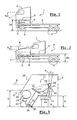
- la Figure 1 représente une vue latérale d'un camion du type circulant en Europe ;
- la Figure 2 représente une vue latérale d'un camion du type circulant aux Etats-Unis ;
- la Figure 3 représente une vue latérale partielle d'une cabine avec un poste de conduite de type traditionnel ;
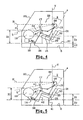
- la Figure 4 représente une vue latérale partielle d'une cabine avec un poste de conduite selon un premier mode de réalisation ; et
- la Figure 5 représente une vue latérale partielle d'une cabine avec un poste de conduite selon un deuxième mode de réalisation.
- Un véhicule industriel (1), du type circulant en Europe, comprend un châssis (2), des roues (3), une cabine (4), des organes mécaniques dont un moteur (6) et un groupe de refroidissement (7). A titre d'exemple, le véhicule (1), illustré à la Figure 1, est un modèle Magnum® de la Demanderesse. Pour ce type de véhicule (1), la cabine (4) est montée au-dessus des deux roues avant (3), du moteur (6) et du groupe de refroidissement (7) selon une architecture à cabine avancée.
- La hauteur (D1), prise à la verticale, entre le plancher (5) de la cabine (4) et le sol est sensiblement comprise entre 1400 mm et 1600 mm, le sol, le véhicule (1), la cabine (4) et le plancher (5) étant sensiblement à l'horizontale. L'angle (α1) correspondant à la visibilité frontale du conducteur est sensiblement compris entre 20° et 30°.
- Un véhicule industriel (8), du type circulant aux Etats-Unis, comprend un châssis (2), des roues (3), une cabine (4), des organes mécaniques dont un moteur (6) et un groupe de refroidissement (7). Le véhicule (8), illustré à la Figure 2, est un modèle Vision® de la société Mack. Pour ce type de véhicule (8), la cabine (4) est montée au-dessus des deux roues avant (3), du moteur (6) et du groupe de refroidissement (7) selon une architecture à cabine arrière moteur.
- La hauteur (D2), prise à la verticale, entre le plancher (5) de la cabine (4) et le sol est sensiblement comprise entre 1200 mm et 1400 mm, le sol, le véhicule (1), la cabine (4) et le plancher (5) étant sensiblement à l'horizontale. Un capot (9) vient couvrir le moteur (6) et le groupe de refroidissement (7). L'angle (α2) correspondant à la visibilité frontale du conducteur est sensiblement compris entre 12° et 20°. Cet angle de vision (α2) du conducteur est légèrement inférieur pour les véhicules de ce type (8) circulant aux Etats-Unis, en raison de la présence de ce capot avant (9).
- La cabine (4) comprend un poste de conduite de type traditionnel (11), représenté en Figure 3. Le poste de conduite traditionnel (11) comprend un siège (12) sur lequel est assis le conducteur. Le conducteur est ici représenté de manière très schématique par référence aux points déterminés d'un mannequin (13), de norme SAE Std J826, installé sur le siège (12). Le siège est en deux parties, une assise (14) et un dossier (16).
- Le poste de conduite (11) comprend également un organe de changement de direction, sous la forme d'un volant (17) et au moins un organe de commande à pédale (18), sous la forme d'une pédale, par exemple pédale d'accélération, de freinage, ... Le poste de conduite (11) comprend un tableau de bord (19). Sous le tableau de bord (19) est fixé le mécanisme de transmission (21) de l'organe de commande à pédale (18). Une colonne de direction (22) passe sous le tableau de bord (19) et transmet les rotations du volant (17) aux roues (3) de manière connue en soi. A l'avant, la cabine (4) et le poste de conduite (11) sont délimités par le pare-brise avant (23).
- L'angle de vision (α, α1 et α2) du poste de conduite traditionnel (11) est ici défini entre la direction horizontale (H) passant par la tête (24) et plus particulièrement par les yeux (26) du mannequin (13) et la direction orientée vers le bas (L) passant par la tête (24) et plus particulièrement par les yeux (26) du mannequin (13) et limitée par la base (27) du pare-brise (23) et/ou par le tableau de bord (19).
- Dans les cabines de type traditionnel (4), la hauteur (X) de la planche de bord (19), qui est définie à la verticale entre la surface supérieure de la planche de bord (19) et le plancher (5) de la cabine (4) dans l'axe du siège (12), est comprise entre 735 mm et 845 mm, les cabines (4) et le plancher (5) étant sensiblement à l'horizontale.
- Dans la cabine de type traditionnelle (4), le siège (12) du poste de conduite (11) présente une assise (14) sensiblement horizontale. En d'autres termes, cette assise (14) présente ainsi une surface supérieure qui est sensiblement horizontale. Le mannequin SAE Std J826 (13) installé sur le siège aura ainsi son fémur (15) positionné à l'horizontal.
- Cette assise (14) se trouve à une hauteur déterminée par rapport au plancher (5) qui est réglable. Cette hauteur est telle que, le point hanche et/ou le fémur (15) du mannequin SAE Std J826 (13) installé sur le siège se trouvent à une hauteur (Z), prise à la verticale, comprise entre 400 mm et 550 mm par rapport au plancher (5), ce dernier étant sensiblement à l'horizontale. L'angle (γ) du dossier (16) est réglable et varie entre 0° et 25° par rapport à la verticale (V). La valeur utilisée par les conducteurs est en moyenne de 15° par rapport à la verticale (V).
- Conformément à l'invention et dans un premier mode de réalisation d'un poste de conduite (28), comme l'illustre la Figure 4, le dossier (32) du siège (31) est incliné vers l'arrière de la cabine (4). L'angle d'inclinaison (γ) du dossier (32) est réglable et varie entre 18° et 30° par rapport à la verticale (V). A titre d'exemple, une valeur de l'angle (γ) pourra être de 25°. Le confort du siège (31) est nettement accru.
- L'assise (29) du siège (31) est également inclinée vers l'arrière de la cabine (4) selon un angle (β). L'angle d'inclinaison (β) est ici défini par rapport à l'inclinaison du fémur (15), c'est-à-dire du segment de droite passant par le point hanche (33) et le point genou (34) du mannequin SAE Std J826 (13) installé sur le siège (31), par rapport à l'horizontale, ou par rapport au plancher (5) de la cabine (4). L'assise (29) présente ainsi un angle (β) compris entre 10° et 20°. A titre d'exemple, une valeur de l'angle (β) pourra être de 15°.
- La hauteur (Z1) du siège (31) est définie à la verticale entre le point hanche (33) du mannequin SAE Std J826 (13) installé sur le siège (31) et le point talon (36) du mannequin SAE Std J826 (13). La hauteur (Z1) du siège (31) varie ainsi entre 300 mm et 400 mm par rapport à ce point talon (36). Les positions de conduite les mieux appréciées des conducteurs sont telles que leur hanche se trouve à une hauteur (Z1) proche de 300 mm, et non plus à une hauteur (Z) présentant des valeurs de 400 mm à 550 mm dans les cabines de type traditionnelle (4).
- En baissant la hauteur du siège (31), il faut pouvoir conserver la même vision rapprochée (même angle α) à travers le pare brise (23) et au dessus de la planche de bord (19). Pour ce faire, dans le premier mode de réalisation, la hauteur (X1) de la planche de bord (19) est comprise entre 500 mm et 600 mm. Cette hauteur (X1) est définie à la verticale entre la surface supérieure de la planche de bord (19) et le point talon (36) du mannequin SAE Std J826 (13) installé dans le siège (31), dans l'axe du siège (31). Cette hauteur (X1) a été réduite d'une valeur sensiblement comprise entre 50 mm et 200 mm, par rapport aux valeurs traditionnellement utilisées de 735 mm à 845 mm. Cette hauteur (X1) n'affecte que le poste de conduite (28) et non la totalité de la planche de bord sur toute la largeur de la cabine (4).
- Le point talon (36) du mannequin SAE Std J826 (13) est remonté à la verticale par rapport au plancher (5) de la cabine (4) d'une valeur (Z2) variant entre 50 mm et 200 mm, selon l'amélioration de confort souhaitée. L'organe de commande à pédale (18) est également remonté de la même valeur. En effet, il est techniquement possible de remonter l'organe de commande à pédale (18) d'une valeur variant entre 50 mm et 200 mm, sans remise en cause technique profonde des autres équipements constitutifs de la planche de bord (19), c'est-à-dire appareil de chauffage, distribution d'air, faisceaux électriques....
- Pour ce faire, et dans ce premier mode de réalisation, un deuxième plancher (37) a été disposé sur le plancher (5) de la cabine (4). La hauteur (22) du deuxième plancher (37), prise à la verticale, sur lequel repose le point talon (36) du mannequin SAE Std J826 (13), varie entre 50 mm et 200 mm par rapport au plancher (5) de la cabine (4), cette cabine (4), son plancher (5) et le deuxième plancher (37) étant sensiblement à l'horizontale. Cette remontée n'affecte que le poste de conduite (28), mais elle ne touche en aucun cas la partie passager et/ou la partie centrale de la planche de bord (19). La hauteur du siège (31) par rapport au plancher (5) de la cabine (4) reste inchangée.
- De plus, ce premier mode de réalisation est tout à fait transposable pour les véhicules circulants aux Etats-Unis (8). La position des yeux (26) du mannequin (13) n'étant pas modifiée par rapport au capot moteur (9), la visibilité vers l'avant (angle α) reste identique.
- Cette solution a fait l'objet de deux prototypes sur la base de modèles existant, à savoir les modèles Magnum® de la Demanderesse et Vision® de la société Mack. Un test a été effectué sur un échantillon de quinze chauffeurs expérimentés professionnels roulant sur des parcours variés autoroutiers et périurbains d'environ 300 km. Ce test a été mené par la Demanderesse et par la société Mack Trucks aux Etats-Unis.
- Les résultats obtenus lors des tests ont été extrêmement positifs. En effet, il a été reconnu que cette nouvelle position de conduite permet un gain en confort très important par rapport aux véhicules actuels. Une amélioration statistique de trois points sur dix a été perçue sur l'appréciation du confort de conduite.
- Conformément à l'invention et dans un deuxième mode de réalisation d'un poste de conduite (38), comme l'illustre la Figure 5, le siège (31) présente la même configuration que celle décrite dans le premier mode de réalisation.
- Pour améliorer l'accessibilité au poste de conduite (38), le siège (31) pivote par rapport à un axe (41) situé à proximité de l'intersection de l'assise (29) et du dossier (32), et est équipé d'un repose pied (42). Le repose pied (42) tourne en même temps que le siège (31).
- La hauteur (Z1) du siège (31), définie à la verticale entre le point hanche (33) du mannequin SAE Std J826 (13) installé sur le siège (31) et le point talon (36) du mannequin SAE Std J826 (13), est analogue à celle du premier mode de réalisation. La hauteur (X1) de la planche de bord (19), définie. à la verticale entre la surface supérieure de la planche de bord (19) et le point talon (36) du mannequin SAE Std J826 (13) installé dans le siège (31), dans l'axe du siège (31), est analogue à celle du premier mode de réalisation. La hauteur (22) du siège (31), définie à la verticale entre le point talon (36) du mannequin SAE Std J826 (13) installé sur le siège (31) et le plancher (5) de la cabine (4) est analogue à celle du premier mode de réalisation.
- La présente invention n'est pas limitée aux modes de réalisation décrits et illustrés. De nombreuses modifications peuvent être réalisées, sans pour autant sortir du cadre défini par la portée du jeu de revendications.
Claims (9)
- Cabine intégrant un poste de conduite (28, 38), destinée à un véhicule à moteur (1, 8), comprenant un siège (31) pour conducteur (13) ayant une assise (29) et un dossier (32), un organe de changement de direction (17), une planche de bord (19) et au moins un organe de commande à pédale (18), le conducteur (13) présentant un point talon (36), et lorsque le conducteur (13) est assis en position de conduite sur le siège (31) et lorsque la cabine (4) est à l'horizontale,- le dossier (32) du siège (31) est incliné vers l'arrière de la cabine (4) et présente un angle (γ) sensiblement compris entre 18° et 30° par rapport à la verticale (V), et- le siège (31) présente une hauteur (Z1), à la verticale, sensiblement comprise entre 300 mm et 400 mm par rapport au point talon (36) ;caractérisée en ce que- le véhicule à moteur (1, 8) est un véhicule industriel routier avec une hauteur entre le plancher (5) et le sol supérieure à 1200 mm, et- la planche de bord (19) présente une hauteur (X1), à la verticale, au moins au niveau de l'organe de changement de direction (17), sensiblement comprise entre 500 mm et 600 mm par rapport au point talon (36).
- Cabine selon la revendication 1, caractérisée en ce que le dossier (32) du siège (31) présente un angle (γ) de préférence sensiblement égal à 25° par rapport à la verticale (V).
- Cabine selon la revendication 1 ou 2, caractérisée en ce que le siège (31) présente une hauteur (Z1), à la verticale, de préférence sensiblement égale à 350 mm par rapport au point talon (36).
- Cabine selon l'une des revendications précédentes, caractérisée en ce que la planche de bord (19) présente une hauteur (X1), à la verticale, de préférence sensiblement égale à 550 mm par rapport au point talon (36).
- Cabine selon l'une des revendications précédentes, caractérisée en ce que l'assise (29) du siège (31) est inclinée vers l'arrière de la cabine (4) et présente un angle (β) sensiblement compris entre 10° et 20° par rapport à l'horizontale, de préférence sensiblement égal à 15° par rapport à l'horizontale.
- Cabine selon l'une des revendications précédentes, caractérisée en ce que la hauteur (Z2) du point talon (36), à la verticale, est sensiblement comprise entre 50 mm et 200 mm par rapport au plancher (5) de la cabine (4), de préférence sensiblement égale à 175 mm par rapport au plancher (5) de la cabine (4).
- Cabine selon la revendication 6, caractérisée en ce que le poste de conduite (28) comprend un deuxième plancher (37) surélevé d'une valeur correspondant à la hauteur du point talon (36).
- Cabine selon la revendication 7, caractérisée en ce que le siège (31) est monté pivotant par rapport au plancher (5) de la cabine (4).
- Véhicule à moteur caractérisé en ce qu'il est équipé d'une cabine (4) intégrant un poste de conduite (28, 38) selon l'une des revendications précédentes.
Applications Claiming Priority (3)
| Application Number | Priority Date | Filing Date | Title |
|---|---|---|---|
| FR0301589A FR2850942B1 (fr) | 2003-02-11 | 2003-02-11 | Cabine a poste de conduite pour vehicule a moteur |
| FR0301589 | 2003-02-11 | ||
| PCT/EP2004/050076 WO2004071809A2 (fr) | 2003-02-11 | 2004-02-03 | Cabine a poste de conduite pour vehicule a moteur |
Publications (2)
| Publication Number | Publication Date |
|---|---|
| EP1592606A2 EP1592606A2 (fr) | 2005-11-09 |
| EP1592606B1 true EP1592606B1 (fr) | 2006-06-28 |
Family
ID=32731931
Family Applications (1)
| Application Number | Title | Priority Date | Filing Date |
|---|---|---|---|
| EP04707536A Expired - Lifetime EP1592606B1 (fr) | 2003-02-11 | 2004-02-03 | Cabine a poste de conduite pour vehicule a moteur |
Country Status (5)
| Country | Link |
|---|---|
| EP (1) | EP1592606B1 (fr) |
| AT (1) | ATE331652T1 (fr) |
| DE (1) | DE602004001392T2 (fr) |
| FR (1) | FR2850942B1 (fr) |
| WO (1) | WO2004071809A2 (fr) |
Families Citing this family (3)
| Publication number | Priority date | Publication date | Assignee | Title |
|---|---|---|---|---|
| GB2425052A (en) * | 2005-04-14 | 2006-10-18 | David Nield | Height adjustable car seat |
| US9827875B2 (en) * | 2015-08-28 | 2017-11-28 | Faraday&Future Inc. | Driver visibility enhancing seat adjustment |
| DE102022100459A1 (de) | 2022-01-11 | 2023-07-13 | Man Truck & Bus Se | Fahrerhaus für Lastkraftwagen |
Family Cites Families (4)
| Publication number | Priority date | Publication date | Assignee | Title |
|---|---|---|---|---|
| SE469426B (sv) * | 1991-11-18 | 1993-07-05 | Bt Ind Ab | Skjutstativtruck med lutningsbar foerarplats |
| EP1019693B1 (fr) * | 1997-10-10 | 2005-07-20 | The Board Of Trustees Of The Michigan State University | Gabarit de dessin de sieges pour personnes |
| DE19962714A1 (de) * | 1999-12-23 | 2001-06-28 | Still Gmbh | Schwenksitz |
| US6450530B1 (en) * | 2000-10-17 | 2002-09-17 | Ford Global Technologies, Inc. | Seating system with optimum visibilty |
-
2003
- 2003-02-11 FR FR0301589A patent/FR2850942B1/fr not_active Expired - Fee Related
-
2004
- 2004-02-03 WO PCT/EP2004/050076 patent/WO2004071809A2/fr not_active Ceased
- 2004-02-03 AT AT04707536T patent/ATE331652T1/de not_active IP Right Cessation
- 2004-02-03 DE DE602004001392T patent/DE602004001392T2/de not_active Expired - Lifetime
- 2004-02-03 EP EP04707536A patent/EP1592606B1/fr not_active Expired - Lifetime
Also Published As
| Publication number | Publication date |
|---|---|
| DE602004001392D1 (de) | 2006-08-10 |
| WO2004071809A2 (fr) | 2004-08-26 |
| WO2004071809A3 (fr) | 2004-11-25 |
| FR2850942A1 (fr) | 2004-08-13 |
| ATE331652T1 (de) | 2006-07-15 |
| FR2850942B1 (fr) | 2006-02-17 |
| DE602004001392T2 (de) | 2007-07-12 |
| EP1592606A2 (fr) | 2005-11-09 |
Similar Documents
| Publication | Publication Date | Title |
|---|---|---|
| US11634060B2 (en) | Side-by-side utility vehicle | |
| US7874605B2 (en) | Utility vehicle | |
| US9878650B2 (en) | Side-by-side vehicle | |
| US8465077B2 (en) | Adjustable seating assemblies for vehicles | |
| US20070228795A1 (en) | Seat for a driver of a construction machine, as well as construction machine | |
| FR3068309A1 (fr) | Habitacle de vehicule ammenageable | |
| FR2742889A1 (fr) | Dispositif d'elements de commande du mouvement longitudinal et du mouvement transversal d'un vehicule automobile ou d'un des deux | |
| FR3066733A1 (fr) | Siege de vehicule comprenant un dispositif d'affichage | |
| US7967388B2 (en) | Vehicle backrest structure | |
| FR3101583A1 (fr) | Procédé de gestion du confort et de la sécurité d’un passager assis sur un siège arrière d’un véhicule. | |
| WO2005108152A3 (fr) | Siege de vehicule d'acces facilite | |
| EP1592606A2 (fr) | Cabine a poste de conduite pour vehicule a moteur | |
| FR2911305A1 (fr) | Siege avec moyens de reglage pour vehicule automobile | |
| EP3661805A1 (fr) | Garniture de siege multifonction pour vehicule automobile | |
| FR2911306A3 (fr) | Siege a capacite d'inversion pour vehicule automobile | |
| FR3142958A1 (fr) | Dispositif repose-pied d’un véhicule automobile | |
| JP4071543B2 (ja) | 車両用シート構造 | |
| FR3167096A1 (fr) | Console centrale d’un véhicule automobile et véhicule automobile | |
| JPH037219Y2 (fr) | ||
| FR2885088A1 (fr) | Ensemble de sieges pour vehicule automobile | |
| FR2717426A1 (fr) | Dispositif de répartition d'air dans l'habitacle d'un véhicule automobile. | |
| FR2945239A1 (fr) | Diffuseur a base de menthe poirvree | |
| US10059243B2 (en) | Motor vehicle having a sloping footrest | |
| FR2889825A3 (fr) | Agencement d'habitacle de vehicule comportant des sieges mobiles | |
| FR2878046A1 (fr) | Vehicule de loisir a pedalier reglable |
Legal Events
| Date | Code | Title | Description |
|---|---|---|---|
| PUAI | Public reference made under article 153(3) epc to a published international application that has entered the european phase |
Free format text: ORIGINAL CODE: 0009012 |
|
| 17P | Request for examination filed |
Effective date: 20050629 |
|
| AK | Designated contracting states |
Kind code of ref document: A2 Designated state(s): AT BE BG CH CY CZ DE DK EE ES FI FR GB GR HU IE IT LI LU MC NL PT RO SE SI SK TR |
|
| AX | Request for extension of the european patent |
Extension state: AL LT LV MK |
|
| GRAP | Despatch of communication of intention to grant a patent |
Free format text: ORIGINAL CODE: EPIDOSNIGR1 |
|
| DAX | Request for extension of the european patent (deleted) | ||
| RAP1 | Party data changed (applicant data changed or rights of an application transferred) |
Owner name: RENAULT TRUCKS |
|
| GRAS | Grant fee paid |
Free format text: ORIGINAL CODE: EPIDOSNIGR3 |
|
| GRAA | (expected) grant |
Free format text: ORIGINAL CODE: 0009210 |
|
| AK | Designated contracting states |
Kind code of ref document: B1 Designated state(s): AT BE BG CH CY CZ DE DK EE ES FI FR GB GR HU IE IT LI LU MC NL PT RO SE SI SK TR |
|
| PG25 | Lapsed in a contracting state [announced via postgrant information from national office to epo] |
Ref country code: IT Free format text: LAPSE BECAUSE OF FAILURE TO SUBMIT A TRANSLATION OF THE DESCRIPTION OR TO PAY THE FEE WITHIN THE PRESCRIBED TIME-LIMIT;WARNING: LAPSES OF ITALIAN PATENTS WITH EFFECTIVE DATE BEFORE 2007 MAY HAVE OCCURRED AT ANY TIME BEFORE 2007. THE CORRECT EFFECTIVE DATE MAY BE DIFFERENT FROM THE ONE RECORDED. Effective date: 20060628 Ref country code: SK Free format text: LAPSE BECAUSE OF FAILURE TO SUBMIT A TRANSLATION OF THE DESCRIPTION OR TO PAY THE FEE WITHIN THE PRESCRIBED TIME-LIMIT Effective date: 20060628 Ref country code: RO Free format text: LAPSE BECAUSE OF FAILURE TO SUBMIT A TRANSLATION OF THE DESCRIPTION OR TO PAY THE FEE WITHIN THE PRESCRIBED TIME-LIMIT Effective date: 20060628 Ref country code: NL Free format text: LAPSE BECAUSE OF FAILURE TO SUBMIT A TRANSLATION OF THE DESCRIPTION OR TO PAY THE FEE WITHIN THE PRESCRIBED TIME-LIMIT Effective date: 20060628 Ref country code: SI Free format text: LAPSE BECAUSE OF FAILURE TO SUBMIT A TRANSLATION OF THE DESCRIPTION OR TO PAY THE FEE WITHIN THE PRESCRIBED TIME-LIMIT Effective date: 20060628 Ref country code: GB Free format text: LAPSE BECAUSE OF FAILURE TO SUBMIT A TRANSLATION OF THE DESCRIPTION OR TO PAY THE FEE WITHIN THE PRESCRIBED TIME-LIMIT Effective date: 20060628 Ref country code: IE Free format text: LAPSE BECAUSE OF FAILURE TO SUBMIT A TRANSLATION OF THE DESCRIPTION OR TO PAY THE FEE WITHIN THE PRESCRIBED TIME-LIMIT Effective date: 20060628 Ref country code: FI Free format text: LAPSE BECAUSE OF FAILURE TO SUBMIT A TRANSLATION OF THE DESCRIPTION OR TO PAY THE FEE WITHIN THE PRESCRIBED TIME-LIMIT Effective date: 20060628 Ref country code: AT Free format text: LAPSE BECAUSE OF FAILURE TO SUBMIT A TRANSLATION OF THE DESCRIPTION OR TO PAY THE FEE WITHIN THE PRESCRIBED TIME-LIMIT Effective date: 20060628 Ref country code: CZ Free format text: LAPSE BECAUSE OF FAILURE TO SUBMIT A TRANSLATION OF THE DESCRIPTION OR TO PAY THE FEE WITHIN THE PRESCRIBED TIME-LIMIT Effective date: 20060628 |
|
| REG | Reference to a national code |
Ref country code: GB Ref legal event code: FG4D Free format text: NOT ENGLISH |
|
| REG | Reference to a national code |
Ref country code: CH Ref legal event code: EP |
|
| REG | Reference to a national code |
Ref country code: IE Ref legal event code: FG4D Free format text: LANGUAGE OF EP DOCUMENT: FRENCH |
|
| REF | Corresponds to: |
Ref document number: 602004001392 Country of ref document: DE Date of ref document: 20060810 Kind code of ref document: P |
|
| PG25 | Lapsed in a contracting state [announced via postgrant information from national office to epo] |
Ref country code: DK Free format text: LAPSE BECAUSE OF FAILURE TO SUBMIT A TRANSLATION OF THE DESCRIPTION OR TO PAY THE FEE WITHIN THE PRESCRIBED TIME-LIMIT Effective date: 20060928 |
|
| PG25 | Lapsed in a contracting state [announced via postgrant information from national office to epo] |
Ref country code: ES Free format text: LAPSE BECAUSE OF FAILURE TO SUBMIT A TRANSLATION OF THE DESCRIPTION OR TO PAY THE FEE WITHIN THE PRESCRIBED TIME-LIMIT Effective date: 20061009 |
|
| REG | Reference to a national code |
Ref country code: SE Ref legal event code: TRGR |
|
| PG25 | Lapsed in a contracting state [announced via postgrant information from national office to epo] |
Ref country code: PT Free format text: LAPSE BECAUSE OF FAILURE TO SUBMIT A TRANSLATION OF THE DESCRIPTION OR TO PAY THE FEE WITHIN THE PRESCRIBED TIME-LIMIT Effective date: 20061128 |
|
| NLV1 | Nl: lapsed or annulled due to failure to fulfill the requirements of art. 29p and 29m of the patents act | ||
| GBV | Gb: ep patent (uk) treated as always having been void in accordance with gb section 77(7)/1977 [no translation filed] |
Effective date: 20060628 |
|
| REG | Reference to a national code |
Ref country code: IE Ref legal event code: FD4D |
|
| PG25 | Lapsed in a contracting state [announced via postgrant information from national office to epo] |
Ref country code: MC Free format text: LAPSE BECAUSE OF NON-PAYMENT OF DUE FEES Effective date: 20070228 |
|
| PLBE | No opposition filed within time limit |
Free format text: ORIGINAL CODE: 0009261 |
|
| STAA | Information on the status of an ep patent application or granted ep patent |
Free format text: STATUS: NO OPPOSITION FILED WITHIN TIME LIMIT |
|
| 26N | No opposition filed |
Effective date: 20070329 |
|
| BERE | Be: lapsed |
Owner name: RENAULT TRUCKS Effective date: 20070228 |
|
| PG25 | Lapsed in a contracting state [announced via postgrant information from national office to epo] |
Ref country code: BE Free format text: LAPSE BECAUSE OF NON-PAYMENT OF DUE FEES Effective date: 20070228 |
|
| PG25 | Lapsed in a contracting state [announced via postgrant information from national office to epo] |
Ref country code: GR Free format text: LAPSE BECAUSE OF FAILURE TO SUBMIT A TRANSLATION OF THE DESCRIPTION OR TO PAY THE FEE WITHIN THE PRESCRIBED TIME-LIMIT Effective date: 20060929 |
|
| PG25 | Lapsed in a contracting state [announced via postgrant information from national office to epo] |
Ref country code: BG Free format text: LAPSE BECAUSE OF FAILURE TO SUBMIT A TRANSLATION OF THE DESCRIPTION OR TO PAY THE FEE WITHIN THE PRESCRIBED TIME-LIMIT Effective date: 20060928 |
|
| PG25 | Lapsed in a contracting state [announced via postgrant information from national office to epo] |
Ref country code: EE Free format text: LAPSE BECAUSE OF FAILURE TO SUBMIT A TRANSLATION OF THE DESCRIPTION OR TO PAY THE FEE WITHIN THE PRESCRIBED TIME-LIMIT Effective date: 20060628 |
|
| REG | Reference to a national code |
Ref country code: CH Ref legal event code: PL |
|
| PG25 | Lapsed in a contracting state [announced via postgrant information from national office to epo] |
Ref country code: LI Free format text: LAPSE BECAUSE OF NON-PAYMENT OF DUE FEES Effective date: 20080229 Ref country code: CH Free format text: LAPSE BECAUSE OF NON-PAYMENT OF DUE FEES Effective date: 20080229 |
|
| PG25 | Lapsed in a contracting state [announced via postgrant information from national office to epo] |
Ref country code: CY Free format text: LAPSE BECAUSE OF FAILURE TO SUBMIT A TRANSLATION OF THE DESCRIPTION OR TO PAY THE FEE WITHIN THE PRESCRIBED TIME-LIMIT Effective date: 20060628 Ref country code: LU Free format text: LAPSE BECAUSE OF NON-PAYMENT OF DUE FEES Effective date: 20070203 |
|
| PG25 | Lapsed in a contracting state [announced via postgrant information from national office to epo] |
Ref country code: TR Free format text: LAPSE BECAUSE OF FAILURE TO SUBMIT A TRANSLATION OF THE DESCRIPTION OR TO PAY THE FEE WITHIN THE PRESCRIBED TIME-LIMIT Effective date: 20060628 Ref country code: HU Free format text: LAPSE BECAUSE OF FAILURE TO SUBMIT A TRANSLATION OF THE DESCRIPTION OR TO PAY THE FEE WITHIN THE PRESCRIBED TIME-LIMIT Effective date: 20061229 |
|
| PGFP | Annual fee paid to national office [announced via postgrant information from national office to epo] |
Ref country code: IT Payment date: 20120214 Year of fee payment: 9 |
|
| PGFP | Annual fee paid to national office [announced via postgrant information from national office to epo] |
Ref country code: DE Payment date: 20140129 Year of fee payment: 11 Ref country code: SE Payment date: 20140211 Year of fee payment: 11 |
|
| PGFP | Annual fee paid to national office [announced via postgrant information from national office to epo] |
Ref country code: FR Payment date: 20140211 Year of fee payment: 11 |
|
| REG | Reference to a national code |
Ref country code: DE Ref legal event code: R082 Ref document number: 602004001392 Country of ref document: DE Representative=s name: V. FUENER EBBINGHAUS FINCK HANO, DE |
|
| REG | Reference to a national code |
Ref country code: DE Ref legal event code: R082 Ref document number: 602004001392 Country of ref document: DE Representative=s name: V. FUENER EBBINGHAUS FINCK HANO, DE Effective date: 20141219 Ref country code: DE Ref legal event code: R081 Ref document number: 602004001392 Country of ref document: DE Owner name: VOLVO TRUCK CORP., SE Free format text: FORMER OWNER: RENAULT TRUCKS, SAINT PRIEST, FR Effective date: 20141219 |
|
| REG | Reference to a national code |
Ref country code: FR Ref legal event code: TP Owner name: VOLVO LASTVAGNAR AKTIEBOLAG, SE Effective date: 20150209 |
|
| REG | Reference to a national code |
Ref country code: DE Ref legal event code: R119 Ref document number: 602004001392 Country of ref document: DE |
|
| REG | Reference to a national code |
Ref country code: SE Ref legal event code: EUG |
|
| REG | Reference to a national code |
Ref country code: FR Ref legal event code: ST Effective date: 20151030 |
|
| PG25 | Lapsed in a contracting state [announced via postgrant information from national office to epo] |
Ref country code: SE Free format text: LAPSE BECAUSE OF NON-PAYMENT OF DUE FEES Effective date: 20150204 |
|
| PG25 | Lapsed in a contracting state [announced via postgrant information from national office to epo] |
Ref country code: DE Free format text: LAPSE BECAUSE OF NON-PAYMENT OF DUE FEES Effective date: 20150901 |
|
| PG25 | Lapsed in a contracting state [announced via postgrant information from national office to epo] |
Ref country code: FR Free format text: LAPSE BECAUSE OF NON-PAYMENT OF DUE FEES Effective date: 20150302 |
|
| PG25 | Lapsed in a contracting state [announced via postgrant information from national office to epo] |
Ref country code: IT Free format text: LAPSE BECAUSE OF NON-PAYMENT OF DUE FEES Effective date: 20140203 |