EP1591700A1 - Gleitringdichtung und Verfahren zur Montage einer Gleitringdichtung - Google Patents
Gleitringdichtung und Verfahren zur Montage einer Gleitringdichtung Download PDFInfo
- Publication number
- EP1591700A1 EP1591700A1 EP05007353A EP05007353A EP1591700A1 EP 1591700 A1 EP1591700 A1 EP 1591700A1 EP 05007353 A EP05007353 A EP 05007353A EP 05007353 A EP05007353 A EP 05007353A EP 1591700 A1 EP1591700 A1 EP 1591700A1
- Authority
- EP
- European Patent Office
- Prior art keywords
- mechanical seal
- ring
- sliding ring
- axial
- seal according
- Prior art date
- Legal status (The legal status is an assumption and is not a legal conclusion. Google has not performed a legal analysis and makes no representation as to the accuracy of the status listed.)
- Granted
Links
Images




Classifications
-
- F—MECHANICAL ENGINEERING; LIGHTING; HEATING; WEAPONS; BLASTING
- F16—ENGINEERING ELEMENTS AND UNITS; GENERAL MEASURES FOR PRODUCING AND MAINTAINING EFFECTIVE FUNCTIONING OF MACHINES OR INSTALLATIONS; THERMAL INSULATION IN GENERAL
- F16J—PISTONS; CYLINDERS; SEALINGS
- F16J15/00—Sealings
- F16J15/16—Sealings between relatively-moving surfaces
- F16J15/34—Sealings between relatively-moving surfaces with slip-ring pressed against a more or less radial face on one member
- F16J15/3464—Mounting of the seal
- F16J15/3488—Split-rings
-
- F—MECHANICAL ENGINEERING; LIGHTING; HEATING; WEAPONS; BLASTING
- F16—ENGINEERING ELEMENTS AND UNITS; GENERAL MEASURES FOR PRODUCING AND MAINTAINING EFFECTIVE FUNCTIONING OF MACHINES OR INSTALLATIONS; THERMAL INSULATION IN GENERAL
- F16J—PISTONS; CYLINDERS; SEALINGS
- F16J15/00—Sealings
- F16J15/16—Sealings between relatively-moving surfaces
- F16J15/34—Sealings between relatively-moving surfaces with slip-ring pressed against a more or less radial face on one member
- F16J15/3464—Mounting of the seal
- F16J15/348—Pre-assembled seals, e.g. cartridge seals
- F16J15/3484—Tandem seals
-
- F—MECHANICAL ENGINEERING; LIGHTING; HEATING; WEAPONS; BLASTING
- F16—ENGINEERING ELEMENTS AND UNITS; GENERAL MEASURES FOR PRODUCING AND MAINTAINING EFFECTIVE FUNCTIONING OF MACHINES OR INSTALLATIONS; THERMAL INSULATION IN GENERAL
- F16J—PISTONS; CYLINDERS; SEALINGS
- F16J15/00—Sealings
- F16J15/44—Free-space packings
- F16J15/447—Labyrinth packings
- F16J15/4472—Labyrinth packings with axial path
Definitions
- the invention relates to a mechanical seal according to the preamble of the first Claim and a method of assembly according to the preamble of claim 10.
- the sealing effect depends more on the gap width than on the gap length.
- the gap width is easier to control with axial seals, in particular narrower gaps can be achieved than with radial seals. Therefore, axial mechanical seals are mostly used (Müller, Nau: Handbuch Dichtungstechnik, eg www.fach hunters-dichtungstechnik.de). So that the sealing effect can be ensured, an axial force must press the stationary and the rotating seal ring together.
- This can be realized by springs, such an example teaches DE-PS 37 40 694.
- DE-PS 41 15 155 To achieve a good support of the slip rings shaft and housing side and at the same time to achieve a high density, more components are needed. This can be elaborately shaped elastomer components, see DE-PS 41 15 155, whose special shape is intended to absorb the burdens due to the conveyed medium or pressure differences.
- DE-OS 100 56 102 shows an adaptation of the slip rings by using suitable materials (in the given case silicon carbide and carbon-silicon carbide composite) to special circumstances.
- suitable materials in the given case silicon carbide and carbon-silicon carbide composite.
- the mechanical seals taught in the prior art have a large number of individual components which must be combined together to make the seal. Thus, a lot of construction volume is needed, the overall ratio of sealing surface and required volume is unfavorable. This volume makes it difficult to use in devices where it often comes down to a compact size with maximum sealing effect. The high number of parts also makes manufacturing and assembly time consuming and expensive. Due to the inherent friction between the slip rings and the low cooling occurs a high heat development.
- the invention is therefore based on the object, as compact as possible Mechanical seal to build with the best possible sealing effect. Your structure should also be as simple as possible, the production costs should be reduced. Farther the invention has the object, this mechanical seal with a possible simple method to assemble.
- the inventive design of the mechanical seal allows a very high tightness with the least possible use of components and volume.
- the structure is significantly simplified compared to the prior art, whereby costs are saved to a considerable extent.
- the choice of material allows the use also in devices with harmful environment, such as flow or displacement machines for the promotion of reactive gases.
- the material used in addition to the tribological properties, it must be taken into account that the material used has the least possible plastic deformation during breakage.
- the inventive design of the seal also makes it possible to minimize the influence of the heat effects occurring during operation, in particular the material expansion, on the sealing and operating properties.
- the seal also has small noxious spaces, making it possible to use in devices in which harmful spaces are critical, such as vacuum pumps. In the latter application, the impact strength increasingly plays a role.
- the seal of the invention is advantageous because it can handle pressure surges very well.
- the life of the seal is increased because the load is distributed from one to several surfaces. This reduces the pressing of the surfaces brought about by the axial force, which reduces the abrasion.
- the axial force can be generated in various ways, for example via a spring element, a pressure difference or acting as a spring elastomer ring. With a suitable choice of the number of sealing surfaces, an optimization of the running and sealing properties can be achieved.
- the sliding ring is first deliberately broken and then the resulting parts are placed around the shaft. These parts are finally pressed together by means of suitable holding means and the shaft together with the fixed sliding ring mounted in the housing of the device.
- FIG. 1 shows a mechanical seal according to the invention.
- the stationary slide ring 105 Between a rotating shaft 101 and a housing 103 is the stationary slide ring 105. This is held over the elastomeric ring 107. The ring also seals the spaces 111 and 113 from each other.
- a spring 109 exerts an axial, in the figure to the right directed force on the slide ring.
- the inside of the sliding ring has a variable inner diameter, whereby a contour 115 is formed.
- the shaft On the rotating component, the shaft, a mating contour 116 is formed. Both contours are in mesh with each other. In the example, this is achieved by designing a part 117 of the shaft to protrude into the slip ring.
- This part is shown as an example as part of the shaft, but it can also be part of a separate, applied to the shaft component.
- the axial force presses the sliding ring against the radial surfaces 119, so that there sets the sealing gap. With radial surfaces such surfaces are designated, the surface normal is parallel to the shaft axis. They are made of a tribologically selected material, in the example steel.
- the slip ring is molded of carbon, ceramic or other frangible material. Because of the projecting into the sliding ring member 117, it can not be pushed onto the shaft. Therefore, it is first broken through by the method according to the invention, so that a plurality of ring pieces arise. These are placed around the wave after breaking.
- the elastomer ring 107 is pushed over the two parts and holds them together.
- the break points can be additionally secured with a suitable adhesive, which also improves the sealing effect.
- the material abrasion occurring during operation of the seal at the sealing surface located inside the sealing ring is collected in chamber 121.
- the friction on the surfaces 119 creates heat, which leads to an increase in temperature and thus to a longitudinal expansion of the part 117 of the shaft.
- the thermally induced length expansions of shaft and seal ring are not the same due to the uneven material pairing and therefore lead to a reduction of the axial gap between part 117 and the contour. This expansion must not lead to a reduction of the sealing gap or even to a tarnish of the part on both sides. This must be taken into account constructively.
- the thickness of the part 117 y and the extent of the recess of the contour x are dimensioned so that their difference is greater than the linear expansion for the maximum temperature to be expected during operation.
- the distance between the surfaces 119 with each other can only be limited in the manufacturing process be adhered to exactly. This provides no for the sliding ring according to the invention Problem is because in a short, compared to the life of small start-up a Self-optimization takes place. At the beginning of the enterprise forms only at one of the Surfaces a sealing gap. At this stage, the abrasion is at this stage reinforced higher forces and thus removed superfluous material. After a short time the sliding ring adapts to the shape and the distance of the surfaces 119.
- FIG. 2 shows the use of a mechanical seal according to the invention in a vacuum pump, for example in a two-shaft positive displacement pump.
- the shaft 201 carries a rotary piston 221 and is mounted in the housing 203.
- the suction chamber 211 should be sealed by the gear chamber 213.
- Between the shaft and the housing sits the symmetrically shaped sliding ring 205 which is held by the elastomeric rings 207 in the housing.
- the slip ring has a variable inner diameter, through which the contour 215 is formed. An axial force may push the slip ring against the surfaces 219a or 219b, depending on the direction of the force.
- a bore 225 in the housing of the pump and a bore 227 in the slide ring itself is used.
- the slide ring of porous material, so that the sealing gas can penetrate through the pores of the slide ring itself.
- two sliding rings according to the invention axially one behind the other and spaced apart from one another in the axial direction and to engage sealing gas between the two rings.
- electro-graphitized charcoal it is particularly advantageous to use as material electro-graphitized charcoal. This choice of material allows adaptation to high ambient temperatures. The maximum compatible ambient temperature then depends only on the choice of the material of the static seal 207.
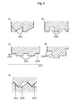
- the shape of the contour (115, 215) is not limited to the examples shown. Further variants are shown in FIG. 3, for example a sawtooth-like contour is conceivable (FIG. 3 a). Furthermore, it is possible to make the recesses 320 differently deep or wide (FIG. 3b). Also conceivable is the variant 3c, in which not recesses occur that correspond to an increase in the radius. Here, rather, the radius of the sliding ring 330 is narrowed at the points 331. It is advantageous if the contours have radial surfaces 333, ie those surfaces whose normal 335 are parallel to the shaft axis 337. A likewise inventive effect achieves the solution of Figure 3d, in which the contour is formed stepwise.
- the individual steps act as individual sealing surfaces.
- the contour can be carried out so that a sealing effect can be achieved in both orientations of the axial force.
- a sawtooth-like contour 341 according to FIG. 3e which meets a sawtooth-like mating contour 343 and is in engagement therewith, represents a possibility for implementing the concept of the invention.
- the thermal expansion of the components is to be considered and correspondingly free space 345 allow.
- variable inner diameter of the stationary slip ring leaves can also be realized by the solution of Figure 4.
- the ring 405 turns off several, but not necessarily identical, identical segments 407 formed, which are oriented over the axial projections 409 to each other.
- An elastomeric ring 415 seals the ring 405 against the housing 403.
- the Components 413 are about sealing rings 417, for example, elastomeric rings against the Shaft sealed.
- the axial force can also take place here through the elastomer ring a spring element or a pressure difference between the spaces to be sealed be generated. This variant also allows a very compact design highest possible sealing effect.
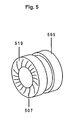
- FIG 5 A further advantageous embodiment is shown in FIG 5. It is known that the axis of rotation vertical sealing surfaces 519 of a mechanical seal 505 to be provided with grooves 507. These cause an enlargement of the sealing gap and thus reduce the Wear. This can also be implemented with the presented seal. Especially It is advantageous to have such grooves on symmetrical rings on both sides of the Insert seal, since they then cause a self-centering of the seal. Furthermore, they allow higher peripheral speeds of the shaft.
- Figure 6 illustrates the necessary for mounting the seal ring 605 according to the invention Method.
- Figure 6a shows the ring as it comes from the manufacturing process. On its end face can be provided predetermined breaking points. This is the end face scratched or sawn at the desired break points.
- the next step is the Ring targeted broken, there are two ring halves 610 and 612 of Figure 6b. These are then placed around the shaft 601 as shown in FIG. 6c and again in such a way put together that the previously formed fracture surfaces sit on each other. Finally, the two halves are secured against falling apart, the for example, by a deferred elastomer ring can happen.
- FIG. 6d shows the ring in the exemplary secured by the elastomeric ring 607 state. It is advantageous, the fracture surfaces 630 in addition by suitable adhesive secure and thus additionally seal.
Landscapes
- Engineering & Computer Science (AREA)
- General Engineering & Computer Science (AREA)
- Mechanical Engineering (AREA)
- Mechanical Sealing (AREA)
Abstract
Description
Damit die Dichtwirkung gewährleistet werden kann, muss eine axiale Kraft den stationären und den rotierenden Gleitring aufeinanderpressen. Dies kann über Federn realisiert werden, ein solches Beispiel lehrt DE-PS 37 40 694. Um eine gute Halterung der Gleitringe wellen- und gehäuseseitig zu erreichen und gleichzeitig eine hohe Dichtheit zu erzielen, sind weitere Bauelemente nötig. Dies können aufwändig geformte Elastomerbauteile sein, siehe DE-PS 41 15 155, deren spezielle Ausformung auch die Belastungen durch das geförderte Medium bzw. Druckdifferenzen auffangen soll.
Die im Stand der Technik gelehrten Gleitringdichtungen weisen eine große Zahl von einzelnen Bauteilen auf, die miteinander kombiniert werden müssen, um die Dichtung zu fertigen. Damit wird viel Bauvolumen benötigt, das Gesamtverhältnis aus Dichtfläche und benötigtem Volumen fällt ungünstig aus. Dieses Volumen erschwert den Einsatz in Geräten, wo es oftmals auf ein kompaktes Maß bei maximaler Dichtwirkung ankommt. Die hohe Zahl der Teile macht zudem Herstellung und Montage zeitaufwändig und teuer.
Aufgrund der prinzipbedingten Reibung zwischen den Gleitringen und der geringen Kühlung tritt eine hohe Wärmeentwicklung auf. Diese Wärme muss kontrolliert abgeführt werden, wobei die Materialwahl nach JP-OS 1120486 eine Lösung bietet. Will man die vorgenannten Dichtungen in Strömungs- oder Verdrängungsmaschinen einsetzen, in denen sich reaktive Gase befinden, stellt sich das Problem, dass viele Bestandteile dieser Dichtungen nur eine geringe Beständigkeit gegen die reaktive Gaslasten aufweisen und eine Anpassung schwierig ist.
Im Stand der Technik ist es bekannt, Gleitringe durch Sägen in drei und mehr Ringsegmente zu zerlegen und anschließend ausreichend viele Ringsegmente wieder zusammen zu fügen, beispielsweise durch Umlegen eines Federspannringes oder durch Einbringen in eine Metallfassung. Das Sägen erzeugt einen Abtrag, der es nicht mehr ermöglicht, die Ringsegmente eines Rohlings zu einem Vollkreis zusammen zu setzen. Deshalb werden Ringsegmente von mehreren Rohlingen verwendet oder es findet alternativ eine Nachbearbeitung der zusammengesetzten Ringsegmente statt. Beide Varianten erhöhen die Herstellungskosten.
In dem zur Montage dieser erfindungsgemäßen Gleitringdichtung notwendigen Verfahren wird der Gleitring zunächst gezielt gebrochen und dann die dadurch entstandenen Teile um die Welle gelegt. Diese Teile werden schließlich durch geeignete Haltemittel aneinandergepresst und die Welle mitsamt dem fixierten Gleitring in das Gehäuse des Geräts montiert. Da das Brechen keinen Materialabtrag an den Bruchflächen erzeugt, können die einzelnen Teile eines Ringes wieder zusammengesetzt werden, ohne dass eine weitere Bearbeitung notwendig ist. Bei den Bruchflächen handelt es sich nicht um glatte sondern um unregelmäßige Flächen, weshalb der aus gebrochenen Teilen zusammengesetzte Gleitring dichter ist als ein aus gesägten Segmenten entstandener Ring. Dieses Verfahren ist sowohl in der Montage als auch in der Demontage der Gleitringe sehr einfach, verursacht keinen Ausschuss, da alle durch das Brechen entstehenden Ringsegmente verwendet werden, und spart dadurch in erheblichem Maße Kosten. Gleichzeitig wird das Ersetzen einer defekten Dichtung deutlich erleichtert, was ebenfalls zu Kosteneinsparungen führt.
Die Kombination des speziellen Gleitrings mit dem Montageverfahren erlaubt die Anordnung der Dichtung an beliebigen Stellen, so werden beispielsweise Hinterschneidungen möglich.
Durch die Reibung an den Flächen 119 entsteht Wärme, die zu einer Temperaturerhöhung und damit zu einer Längenausdehnung des Teils 117 der Welle führt. Die thermisch bedingte Längenausdehnungen von Welle und Gleitring sind aufgrund der ungleichen Materialpaarung nicht gleich und führen daher zu einer Verringerung des axialen Spaltes zwischen Teil 117 und der Kontur. Diese Ausdehnung darf nicht zu einer Reduzierung des Dichtspaltes oder gar zu einem Anlaufen des Teils auf beiden Seiten führen. Dem ist konstruktiv Rechnung zu tragen. Hierzu werden die Dicke des Teils 117 y und das Maß der Ausnehmung der Kontur x so bemessen, dass ihre Differenz größer als die Längenausdehnung für die im Betrieb zu erwartende Maximaltemperatur ist.
Die Dichtwirkung wird gegenüber Gleitringdichtungen aus dem Stand der Technik verbessert, da auf kompaktem Raum mehrere Dichtflächen gleichzeitig wirken. Der Druckabfall über die einzelnen Flächen ist daher jeweils kleiner als im Falle nur einer Dichtfläche. Die Ausformung der Kontur sorgt zudem für eine labyrinthartige Abdichtung.
Je nach Anwendungsfall kann eine Beaufschlagung der Dichtung mit Sperrgas wünschenswert sein. Dazu dient eine Bohrung 225 im Gehäuse der Pumpe und eine Bohrung 227 im Gleitring selbst. Alternativ ist es möglich, den Gleitring aus porösem Material zu fertigen, so dass das Sperrgas durch die Poren des Gleitringes selbst dringen kann. Wiederum alternativ ist möglich, zwei erfindungsgemäße Gleitringe axial hintereinander und in axialer Richtung beabstandet von einander anzuordnen und Sperrgas zwischen beide Ringe einzulassen.
In Vakuumpumpen ist es besonders vorteilhaft, als Material elektrographitierte Kunstkohle, zu verwenden. Diese Materialwahl erlaubt die Anpassung an hohe Umgebungstemperaturen. Die maximal verträgliche Umgebungstemperatur hängt dann nur noch von der Wahl des Materials der statischen Dichtung 207 ab.
Vorteilhaft ist es, wenn die Konturen radiale Flächen 333 aufweisen, also solche Flächen, deren Normale 335 parallel zur Wellenachse 337 sind. Eine ebenfalls erfindungsgemäße Wirkung erzielt die Lösung nach Figur 3d, bei der die Kontur stufenartig ausgebildet ist. Hier wirken die einzelnen Stufen als einzelne Dichtflächen. Auch hier kann die Kontur so ausgeführt werden, dass eine Dichtwirkung bei beiden Ausrichtungen der axialen Kraft erzielt werden kann. Auch eine sägezahnartige Kontur 341 nach Figur 3e, die auf eine ebenfalls sägezahnartige Gegenkontur 343 trifft und mit dieser im Eingriff steht, stellt eine Möglichkeit der Umsetzung des Erfindungsgedankens dar. Bei der Wahl der Sägezahnform ist die thermische Ausdehnung der Bauteile zu Beachten und entsprechend Freiraum 345 zu lassen.
Claims (13)
- Axiale Gleitringdichtung zur Abdichtung einer rotierenden Welle (101) mit stehendem Gleitring, dadurch gekennzeichnet, dass der stehende Gleitring (105) als Zylinder mit variablem Innendurchmesser gestaltet ist, wodurch eine Kontur (115) entsteht, die den Querschnitt des Gleitringes beschreibt und die auf eine angepasste Gegenkontur (116) auf der Welle trifft, so dass beide miteinander im Eingriff stehen.
- Axiale Gleitringdichtung nach Anspruch 1, dadurch gekennzeichnet, dass die durch den variablen Innendurchmesser entstehende Kontur (115, 215) mindestens zwei radiale Flächen (119, 219, 333) aufweist.
- Axiale Gleitringdichtung nach Anspruch 1 oder 2, dadurch gekennzeichnet, dass die axiale Kraft durch einen Elastomerring (415) erzeugt wird.
- Axiale Gleitringdichtung nach Anspruch 1 oder 2, dadurch gekennzeichnet, dass die axiale Kraft durch eine Feder (109) erzeugt wird.
- Axiale Gleitringdichtung nach Anspruch 1 oder 2, dadurch gekennzeichnet, dass die axiale Kraft durch eine Druckdifferenz zwischen den gegeneinander abzudichtenden Räumen (211, 213) erzeugt wird.
- Axiale Gleitringdichtung nach einem der vorhergehenden Ansprüche, dadurch gekennzeichnet, dass die Ausgestaltung der Kontur (115) eine Wirkung der Dichtung für beide Richtungen der axialen Kraft erlaubt.
- Axiale Gleitringdichtung nach einem der vorhergehenden Ansprüche, dadurch gekennzeichnet, dass die Gegenkontur (116) den äußeren Teil des Querschnitt eines separaten Bauteils beschreibt, das an der Welle (101) angebracht ist.
- Axiale Gleitringdichtung nach einem der vorhergehenden Ansprüche, dadurch gekennzeichnet, dass im Gehäuse (203) und im stehenden Gleitring (205) Bohrungen (225, 227) zur Beaufschlagung mit Sperrgas vorhanden sind.
- Axiale Gleitringdichtung nach einem der vorhergehenden Ansprüche, dadurch gekennzeichnet, dass der stehende Gleitring (205) aus porösem Material hergestellt ist.
- Verfahren zur Montage eines Gleitringes einer axialen Gleitringdichtung nach einem der vorhergehenden Ansprüche, dadurch gekennzeichnet, dass der Gleitring zunächst in mindestens zwei Teile (610, 612) zerbrochen wird, die dann um die rotierende Welle (601) gelegt und abschließend gegen Auseinanderfallen gesichert werden.
- Verfahren nach Anspruch 10, dadurch gekennzeichnet, dass das Sichern durch mindestens einen Elastomerring (607) geschieht.
- Verfahren nach Anspruch 10 oder 11, dadurch gekennzeichnet, dass das Sichern das Kleben der Bruchflächen (630) beinhaltet.
- Vakuumpumpe, dadurch gekennzeichnet, dass sie mit einer axialen Gleitringdichtung nach einem der vorhergehenden Ansprüche ausgestattet ist.
Applications Claiming Priority (2)
| Application Number | Priority Date | Filing Date | Title |
|---|---|---|---|
| DE102004021502A DE102004021502A1 (de) | 2004-04-30 | 2004-04-30 | Gleitringdichtung und Verfahren zur Montage einer Gleitringdichtung |
| DE102004021502 | 2004-04-30 |
Publications (2)
| Publication Number | Publication Date |
|---|---|
| EP1591700A1 true EP1591700A1 (de) | 2005-11-02 |
| EP1591700B1 EP1591700B1 (de) | 2008-07-09 |
Family
ID=34934750
Family Applications (1)
| Application Number | Title | Priority Date | Filing Date |
|---|---|---|---|
| EP05007353A Expired - Lifetime EP1591700B1 (de) | 2004-04-30 | 2005-04-05 | Gleitringdichtung und Verfahren zur Montage einer Gleitringdichtung |
Country Status (4)
| Country | Link |
|---|---|
| US (1) | US20050242518A1 (de) |
| EP (1) | EP1591700B1 (de) |
| AT (1) | ATE400754T1 (de) |
| DE (2) | DE102004021502A1 (de) |
Families Citing this family (2)
| Publication number | Priority date | Publication date | Assignee | Title |
|---|---|---|---|---|
| WO2010137521A1 (ja) * | 2009-05-25 | 2010-12-02 | イーグル工業株式会社 | シール装置 |
| CN110985373B (zh) * | 2019-11-22 | 2022-04-19 | 中国航发西安动力控制科技有限公司 | 随动式迷宫密封结构 |
Citations (10)
| Publication number | Priority date | Publication date | Assignee | Title |
|---|---|---|---|---|
| DE187926C (de) * | ||||
| US845701A (en) * | 1906-03-15 | 1907-02-26 | Kerr Turbine Company | Turbine-shaft packing. |
| GB1003913A (en) * | 1961-05-23 | 1965-09-08 | Borg Warner | Mechanical seal assembly |
| DE1950634A1 (de) * | 1969-10-08 | 1971-04-22 | Dornier Ag | Labyrinthdichtung |
| AT308485B (de) * | 1970-09-11 | 1973-07-10 | Eckerle Otto | Verfahren zur Herstellung von Wellendichtungen |
| JPH01120486A (ja) | 1987-10-30 | 1989-05-12 | Toshiba Ceramics Co Ltd | メカニカルシール用摺動リング |
| DE3740694A1 (de) | 1987-12-01 | 1989-06-22 | Goetze Ag | Gleitringdichtung |
| DE4115115A1 (de) | 1990-09-20 | 1992-03-26 | Freudenberg Nok Gp | Gleitringdichtung mit erhoehter lebensdauer |
| US6325381B1 (en) * | 1999-05-04 | 2001-12-04 | System Seals, Inc. | High-pressure rotary seal |
| DE10056102A1 (de) | 2000-11-13 | 2002-06-06 | Freudenberg Carl Kg | Gleitringdichtung |
Family Cites Families (20)
| Publication number | Priority date | Publication date | Assignee | Title |
|---|---|---|---|---|
| US838744A (en) * | 1906-02-05 | 1906-12-18 | Charles Algernon Parsons | Steam-trubine shaft. |
| US2867458A (en) * | 1956-02-23 | 1959-01-06 | Sealol Corp | Shaft seal for gas turbines and the like |
| CH448650A (de) * | 1965-07-23 | 1967-12-15 | Leidenfrost Reinhold | Spalt- bzw. Labyrinthdichtung und Verfahren zu ihrer Herstellung |
| US3357708A (en) * | 1965-09-17 | 1967-12-12 | Gen Motors Corp | Labyrinth seal |
| US3663023A (en) * | 1967-08-11 | 1972-05-16 | Reinhold Leidenfrost | Labyrinth gap seal |
| ES134822Y (es) * | 1967-12-20 | 1968-09-01 | S. A. Fabricacion De Accesorios Para Rodamientos | Dispositivo de estanqueidad para soportes de ejes, perfec- cionado. |
| US3578345A (en) * | 1969-02-03 | 1971-05-11 | John C Copes | Mechanical seal inserts |
| US3971563A (en) * | 1973-09-17 | 1976-07-27 | Mitsui Shipbuilding And Engineering Co., Ltd. | Shaft sealing apparatus using a fluid sealing system |
| US4348067A (en) * | 1980-03-03 | 1982-09-07 | Reliance Electric Company | Bearing seal |
| DD241453A1 (de) * | 1985-09-30 | 1986-12-10 | Barkas Werke Veb | Gleitringdichtung |
| US5487549A (en) * | 1994-10-24 | 1996-01-30 | Demag Delaval Turbomachinery Corp. Turbocare Division | Turbine interfitting packing with cam adjustment |
| FR2729203B1 (fr) * | 1995-01-10 | 1997-04-04 | Poclain Hydraulics Sa | Assemblage pour mecanisme a fluide sous pression comprenant un ensemble d'etancheite |
| US5961122A (en) * | 1995-07-21 | 1999-10-05 | Flowserve Management Company | Split mechanical face seal and method of assembly thereof |
| US5988649A (en) * | 1997-05-01 | 1999-11-23 | E. I. Du Pont De Nemours And Company | Fractured seal ring |
| US6325382B1 (en) * | 1999-05-21 | 2001-12-04 | Nippon Pillar Packing Co., Ltd. | Non-contact type mechanical seal |
| EP1212557A4 (de) * | 1999-07-15 | 2006-05-10 | Christopher Frederick Bayne | Wellendichtringen zum abdichten von feststoffpulvern |
| GB2359863B (en) * | 2000-03-04 | 2003-03-26 | Alstom | Turbocharger |
| GB2368100B (en) * | 2000-10-19 | 2004-02-18 | Rolls Royce Plc | Seal fitting |
| JP2002285802A (ja) * | 2001-03-26 | 2002-10-03 | Toshiba Corp | 回転機械のラビリンスシール装置 |
| US6932350B1 (en) * | 2003-09-26 | 2005-08-23 | Ideal Electric Company | Windback labyrinth seal that accommodates a pressure differential for rotating shafts |
-
2004
- 2004-04-30 DE DE102004021502A patent/DE102004021502A1/de not_active Withdrawn
-
2005
- 2005-04-05 AT AT05007353T patent/ATE400754T1/de not_active IP Right Cessation
- 2005-04-05 EP EP05007353A patent/EP1591700B1/de not_active Expired - Lifetime
- 2005-04-05 DE DE502005004601T patent/DE502005004601D1/de not_active Expired - Lifetime
- 2005-04-27 US US11/116,071 patent/US20050242518A1/en not_active Abandoned
Patent Citations (10)
| Publication number | Priority date | Publication date | Assignee | Title |
|---|---|---|---|---|
| DE187926C (de) * | ||||
| US845701A (en) * | 1906-03-15 | 1907-02-26 | Kerr Turbine Company | Turbine-shaft packing. |
| GB1003913A (en) * | 1961-05-23 | 1965-09-08 | Borg Warner | Mechanical seal assembly |
| DE1950634A1 (de) * | 1969-10-08 | 1971-04-22 | Dornier Ag | Labyrinthdichtung |
| AT308485B (de) * | 1970-09-11 | 1973-07-10 | Eckerle Otto | Verfahren zur Herstellung von Wellendichtungen |
| JPH01120486A (ja) | 1987-10-30 | 1989-05-12 | Toshiba Ceramics Co Ltd | メカニカルシール用摺動リング |
| DE3740694A1 (de) | 1987-12-01 | 1989-06-22 | Goetze Ag | Gleitringdichtung |
| DE4115115A1 (de) | 1990-09-20 | 1992-03-26 | Freudenberg Nok Gp | Gleitringdichtung mit erhoehter lebensdauer |
| US6325381B1 (en) * | 1999-05-04 | 2001-12-04 | System Seals, Inc. | High-pressure rotary seal |
| DE10056102A1 (de) | 2000-11-13 | 2002-06-06 | Freudenberg Carl Kg | Gleitringdichtung |
Also Published As
| Publication number | Publication date |
|---|---|
| ATE400754T1 (de) | 2008-07-15 |
| US20050242518A1 (en) | 2005-11-03 |
| DE102004021502A1 (de) | 2005-11-24 |
| DE502005004601D1 (de) | 2008-08-21 |
| EP1591700B1 (de) | 2008-07-09 |
Similar Documents
| Publication | Publication Date | Title |
|---|---|---|
| DE69937495T2 (de) | Wellendichtung und verfahren zur herstellung | |
| EP3762624B1 (de) | Abgasturbolader mit einem hydrodynamischen gleitlager oder lageranordnung mit einem hydrodynamischen gleitlager | |
| EP2570705B1 (de) | Abstreifring und Abstreiflamelle | |
| DE19738331A1 (de) | Lagerkäfig | |
| DE102009005386A1 (de) | Ladeeinrichtung für eine Brennkraftmaschine | |
| DE102015222270A1 (de) | Modulare turbolader-spaltdichtung | |
| DE102008018545A1 (de) | Welle mit Wälzlager | |
| DE3602051A1 (de) | Waelzlager-drehverbindung | |
| DE102018122000A1 (de) | Wellendichtung mit einem Wellendichtring | |
| EP1722116B1 (de) | Gleitlager | |
| EP3315802A1 (de) | Rotationssystem mit axialer gaslagerung | |
| EP3600731B1 (de) | Verbundbauteil | |
| EP1150018B1 (de) | Dichtungselement für einen Schwenkmotor | |
| AT521716B1 (de) | Ölabstreifring für eine Kolbenstange | |
| DE102016211906A1 (de) | Käfig für Kurbelwellenlagerung | |
| EP1591700B1 (de) | Gleitringdichtung und Verfahren zur Montage einer Gleitringdichtung | |
| DE102019131245A1 (de) | Lageranordnung und Verfahren zum Montieren einer solchen | |
| EP2511551A2 (de) | Wälzlager | |
| WO2019034293A1 (de) | Kolbenringsatz, kolben und verbrennungsmotor | |
| DE102009020110A1 (de) | Hydrostatische Verdrängermaschine mit rollenförmigen Wälzkörpern | |
| WO1996015368A1 (de) | Dichtungsanordnung an einer kolben-zylinder-einheit | |
| EP4058680B1 (de) | Radlagereinheit | |
| DE202017103425U1 (de) | Adapterhülse für Druckmaschinen und Dichtungsring hierfür | |
| EP2305951B1 (de) | Dichtungsanordnung und Drehkolbenmaschine | |
| DE9212923U1 (de) | Gleitringdichtungsanordnung |
Legal Events
| Date | Code | Title | Description |
|---|---|---|---|
| PUAI | Public reference made under article 153(3) epc to a published international application that has entered the european phase |
Free format text: ORIGINAL CODE: 0009012 |
|
| AK | Designated contracting states |
Kind code of ref document: A1 Designated state(s): AT BE BG CH CY CZ DE DK EE ES FI FR GB GR HU IE IS IT LI LT LU MC NL PL PT RO SE SI SK TR |
|
| AX | Request for extension of the european patent |
Extension state: AL BA HR LV MK YU |
|
| 17P | Request for examination filed |
Effective date: 20060418 |
|
| AKX | Designation fees paid |
Designated state(s): AT BE BG CH CY CZ DE DK EE ES FI FR GB GR HU IE IS IT LI LT LU MC NL PL PT RO SE SI SK TR |
|
| 17Q | First examination report despatched |
Effective date: 20060608 |
|
| GRAP | Despatch of communication of intention to grant a patent |
Free format text: ORIGINAL CODE: EPIDOSNIGR1 |
|
| GRAS | Grant fee paid |
Free format text: ORIGINAL CODE: EPIDOSNIGR3 |
|
| GRAA | (expected) grant |
Free format text: ORIGINAL CODE: 0009210 |
|
| AK | Designated contracting states |
Kind code of ref document: B1 Designated state(s): AT BE BG CH CY CZ DE DK EE ES FI FR GB GR HU IE IS IT LI LT LU MC NL PL PT RO SE SI SK TR |
|
| REG | Reference to a national code |
Ref country code: GB Ref legal event code: FG4D Free format text: NOT ENGLISH |
|
| REG | Reference to a national code |
Ref country code: CH Ref legal event code: EP |
|
| REF | Corresponds to: |
Ref document number: 502005004601 Country of ref document: DE Date of ref document: 20080821 Kind code of ref document: P |
|
| REG | Reference to a national code |
Ref country code: IE Ref legal event code: FG4D Free format text: LANGUAGE OF EP DOCUMENT: GERMAN |
|
| NLV1 | Nl: lapsed or annulled due to failure to fulfill the requirements of art. 29p and 29m of the patents act | ||
| PG25 | Lapsed in a contracting state [announced via postgrant information from national office to epo] |
Ref country code: NL Free format text: LAPSE BECAUSE OF FAILURE TO SUBMIT A TRANSLATION OF THE DESCRIPTION OR TO PAY THE FEE WITHIN THE PRESCRIBED TIME-LIMIT Effective date: 20080709 Ref country code: LT Free format text: LAPSE BECAUSE OF FAILURE TO SUBMIT A TRANSLATION OF THE DESCRIPTION OR TO PAY THE FEE WITHIN THE PRESCRIBED TIME-LIMIT Effective date: 20080709 Ref country code: ES Free format text: LAPSE BECAUSE OF FAILURE TO SUBMIT A TRANSLATION OF THE DESCRIPTION OR TO PAY THE FEE WITHIN THE PRESCRIBED TIME-LIMIT Effective date: 20081020 Ref country code: PT Free format text: LAPSE BECAUSE OF FAILURE TO SUBMIT A TRANSLATION OF THE DESCRIPTION OR TO PAY THE FEE WITHIN THE PRESCRIBED TIME-LIMIT Effective date: 20081209 Ref country code: IS Free format text: LAPSE BECAUSE OF FAILURE TO SUBMIT A TRANSLATION OF THE DESCRIPTION OR TO PAY THE FEE WITHIN THE PRESCRIBED TIME-LIMIT Effective date: 20081109 |
|
| PG25 | Lapsed in a contracting state [announced via postgrant information from national office to epo] |
Ref country code: SI Free format text: LAPSE BECAUSE OF FAILURE TO SUBMIT A TRANSLATION OF THE DESCRIPTION OR TO PAY THE FEE WITHIN THE PRESCRIBED TIME-LIMIT Effective date: 20080709 Ref country code: FI Free format text: LAPSE BECAUSE OF FAILURE TO SUBMIT A TRANSLATION OF THE DESCRIPTION OR TO PAY THE FEE WITHIN THE PRESCRIBED TIME-LIMIT Effective date: 20080709 Ref country code: BG Free format text: LAPSE BECAUSE OF FAILURE TO SUBMIT A TRANSLATION OF THE DESCRIPTION OR TO PAY THE FEE WITHIN THE PRESCRIBED TIME-LIMIT Effective date: 20081009 |
|
| REG | Reference to a national code |
Ref country code: IE Ref legal event code: FD4D |
|
| PG25 | Lapsed in a contracting state [announced via postgrant information from national office to epo] |
Ref country code: EE Free format text: LAPSE BECAUSE OF FAILURE TO SUBMIT A TRANSLATION OF THE DESCRIPTION OR TO PAY THE FEE WITHIN THE PRESCRIBED TIME-LIMIT Effective date: 20080709 Ref country code: IE Free format text: LAPSE BECAUSE OF FAILURE TO SUBMIT A TRANSLATION OF THE DESCRIPTION OR TO PAY THE FEE WITHIN THE PRESCRIBED TIME-LIMIT Effective date: 20080709 Ref country code: DK Free format text: LAPSE BECAUSE OF FAILURE TO SUBMIT A TRANSLATION OF THE DESCRIPTION OR TO PAY THE FEE WITHIN THE PRESCRIBED TIME-LIMIT Effective date: 20080709 |
|
| PLBE | No opposition filed within time limit |
Free format text: ORIGINAL CODE: 0009261 |
|
| STAA | Information on the status of an ep patent application or granted ep patent |
Free format text: STATUS: NO OPPOSITION FILED WITHIN TIME LIMIT |
|
| PG25 | Lapsed in a contracting state [announced via postgrant information from national office to epo] |
Ref country code: SK Free format text: LAPSE BECAUSE OF FAILURE TO SUBMIT A TRANSLATION OF THE DESCRIPTION OR TO PAY THE FEE WITHIN THE PRESCRIBED TIME-LIMIT Effective date: 20080709 Ref country code: RO Free format text: LAPSE BECAUSE OF FAILURE TO SUBMIT A TRANSLATION OF THE DESCRIPTION OR TO PAY THE FEE WITHIN THE PRESCRIBED TIME-LIMIT Effective date: 20080709 Ref country code: CZ Free format text: LAPSE BECAUSE OF FAILURE TO SUBMIT A TRANSLATION OF THE DESCRIPTION OR TO PAY THE FEE WITHIN THE PRESCRIBED TIME-LIMIT Effective date: 20080709 |
|
| 26N | No opposition filed |
Effective date: 20090414 |
|
| BERE | Be: lapsed |
Owner name: PFEIFFER VACUUM G.M.B.H. Effective date: 20090430 |
|
| REG | Reference to a national code |
Ref country code: CH Ref legal event code: PL |
|
| PG25 | Lapsed in a contracting state [announced via postgrant information from national office to epo] |
Ref country code: SE Free format text: LAPSE BECAUSE OF FAILURE TO SUBMIT A TRANSLATION OF THE DESCRIPTION OR TO PAY THE FEE WITHIN THE PRESCRIBED TIME-LIMIT Effective date: 20081009 Ref country code: CH Free format text: LAPSE BECAUSE OF NON-PAYMENT OF DUE FEES Effective date: 20090430 Ref country code: LI Free format text: LAPSE BECAUSE OF NON-PAYMENT OF DUE FEES Effective date: 20090430 |
|
| PG25 | Lapsed in a contracting state [announced via postgrant information from national office to epo] |
Ref country code: MC Free format text: LAPSE BECAUSE OF NON-PAYMENT OF DUE FEES Effective date: 20090430 |
|
| PG25 | Lapsed in a contracting state [announced via postgrant information from national office to epo] |
Ref country code: PL Free format text: LAPSE BECAUSE OF FAILURE TO SUBMIT A TRANSLATION OF THE DESCRIPTION OR TO PAY THE FEE WITHIN THE PRESCRIBED TIME-LIMIT Effective date: 20080709 Ref country code: BE Free format text: LAPSE BECAUSE OF NON-PAYMENT OF DUE FEES Effective date: 20090430 |
|
| PG25 | Lapsed in a contracting state [announced via postgrant information from national office to epo] |
Ref country code: AT Free format text: LAPSE BECAUSE OF NON-PAYMENT OF DUE FEES Effective date: 20090405 |
|
| PG25 | Lapsed in a contracting state [announced via postgrant information from national office to epo] |
Ref country code: GR Free format text: LAPSE BECAUSE OF FAILURE TO SUBMIT A TRANSLATION OF THE DESCRIPTION OR TO PAY THE FEE WITHIN THE PRESCRIBED TIME-LIMIT Effective date: 20081010 |
|
| PG25 | Lapsed in a contracting state [announced via postgrant information from national office to epo] |
Ref country code: LU Free format text: LAPSE BECAUSE OF NON-PAYMENT OF DUE FEES Effective date: 20090405 |
|
| PG25 | Lapsed in a contracting state [announced via postgrant information from national office to epo] |
Ref country code: HU Free format text: LAPSE BECAUSE OF FAILURE TO SUBMIT A TRANSLATION OF THE DESCRIPTION OR TO PAY THE FEE WITHIN THE PRESCRIBED TIME-LIMIT Effective date: 20090110 |
|
| PG25 | Lapsed in a contracting state [announced via postgrant information from national office to epo] |
Ref country code: TR Free format text: LAPSE BECAUSE OF FAILURE TO SUBMIT A TRANSLATION OF THE DESCRIPTION OR TO PAY THE FEE WITHIN THE PRESCRIBED TIME-LIMIT Effective date: 20080709 |
|
| PG25 | Lapsed in a contracting state [announced via postgrant information from national office to epo] |
Ref country code: CY Free format text: LAPSE BECAUSE OF FAILURE TO SUBMIT A TRANSLATION OF THE DESCRIPTION OR TO PAY THE FEE WITHIN THE PRESCRIBED TIME-LIMIT Effective date: 20080709 |
|
| PGFP | Annual fee paid to national office [announced via postgrant information from national office to epo] |
Ref country code: FR Payment date: 20120330 Year of fee payment: 8 |
|
| REG | Reference to a national code |
Ref country code: FR Ref legal event code: ST Effective date: 20131231 |
|
| PG25 | Lapsed in a contracting state [announced via postgrant information from national office to epo] |
Ref country code: FR Free format text: LAPSE BECAUSE OF NON-PAYMENT OF DUE FEES Effective date: 20130430 |
|
| PGFP | Annual fee paid to national office [announced via postgrant information from national office to epo] |
Ref country code: IT Payment date: 20210224 Year of fee payment: 17 |
|
| PGFP | Annual fee paid to national office [announced via postgrant information from national office to epo] |
Ref country code: GB Payment date: 20210316 Year of fee payment: 17 |
|
| GBPC | Gb: european patent ceased through non-payment of renewal fee |
Effective date: 20220405 |
|
| PG25 | Lapsed in a contracting state [announced via postgrant information from national office to epo] |
Ref country code: GB Free format text: LAPSE BECAUSE OF NON-PAYMENT OF DUE FEES Effective date: 20220405 |
|
| PGFP | Annual fee paid to national office [announced via postgrant information from national office to epo] |
Ref country code: DE Payment date: 20221026 Year of fee payment: 18 |
|
| PG25 | Lapsed in a contracting state [announced via postgrant information from national office to epo] |
Ref country code: IT Free format text: LAPSE BECAUSE OF NON-PAYMENT OF DUE FEES Effective date: 20220405 |
|
| REG | Reference to a national code |
Ref country code: DE Ref legal event code: R119 Ref document number: 502005004601 Country of ref document: DE |
|
| PG25 | Lapsed in a contracting state [announced via postgrant information from national office to epo] |
Ref country code: DE Free format text: LAPSE BECAUSE OF NON-PAYMENT OF DUE FEES Effective date: 20231103 |