EP1591190A1 - Verfahren zum Verschweissen zweier Metallbleche - Google Patents
Verfahren zum Verschweissen zweier Metallbleche Download PDFInfo
- Publication number
- EP1591190A1 EP1591190A1 EP05300345A EP05300345A EP1591190A1 EP 1591190 A1 EP1591190 A1 EP 1591190A1 EP 05300345 A EP05300345 A EP 05300345A EP 05300345 A EP05300345 A EP 05300345A EP 1591190 A1 EP1591190 A1 EP 1591190A1
- Authority
- EP
- European Patent Office
- Prior art keywords
- welding
- edges
- movable jaw
- laser beam
- strips
- Prior art date
- Legal status (The legal status is an assumption and is not a legal conclusion. Google has not performed a legal analysis and makes no representation as to the accuracy of the status listed.)
- Granted
Links
- 238000003466 welding Methods 0.000 title claims abstract description 67
- 238000000034 method Methods 0.000 title claims description 29
- 239000002184 metal Substances 0.000 title claims description 16
- 229910052751 metal Inorganic materials 0.000 title claims description 16
- 238000005520 cutting process Methods 0.000 claims abstract description 32
- 239000011324 bead Substances 0.000 claims abstract description 19
- 239000000463 material Substances 0.000 claims abstract description 8
- 238000006073 displacement reaction Methods 0.000 claims abstract description 6
- 238000012545 processing Methods 0.000 claims abstract description 6
- 238000011144 upstream manufacturing Methods 0.000 claims abstract description 5
- 238000009434 installation Methods 0.000 claims abstract description 3
- 230000008569 process Effects 0.000 claims description 15
- 238000012986 modification Methods 0.000 claims description 5
- 230000004048 modification Effects 0.000 claims description 5
- 230000007246 mechanism Effects 0.000 abstract description 5
- 239000000945 filler Substances 0.000 abstract 2
- 230000010339 dilation Effects 0.000 description 6
- 229910000831 Steel Inorganic materials 0.000 description 5
- 239000010959 steel Substances 0.000 description 5
- 238000010438 heat treatment Methods 0.000 description 4
- 238000005096 rolling process Methods 0.000 description 4
- 238000010008 shearing Methods 0.000 description 4
- 238000011282 treatment Methods 0.000 description 4
- 230000009471 action Effects 0.000 description 3
- 238000013459 approach Methods 0.000 description 3
- 230000015572 biosynthetic process Effects 0.000 description 3
- 230000007547 defect Effects 0.000 description 3
- 229910001338 liquidmetal Inorganic materials 0.000 description 3
- 230000003287 optical effect Effects 0.000 description 3
- 229910000679 solder Inorganic materials 0.000 description 3
- XEEYBQQBJWHFJM-UHFFFAOYSA-N Iron Chemical compound [Fe] XEEYBQQBJWHFJM-UHFFFAOYSA-N 0.000 description 2
- 238000005097 cold rolling Methods 0.000 description 2
- 230000001788 irregular Effects 0.000 description 2
- 238000004519 manufacturing process Methods 0.000 description 2
- 238000002844 melting Methods 0.000 description 2
- 230000008018 melting Effects 0.000 description 2
- 210000000056 organ Anatomy 0.000 description 2
- 238000000926 separation method Methods 0.000 description 2
- 206010016275 Fear Diseases 0.000 description 1
- 230000008901 benefit Effects 0.000 description 1
- 230000008859 change Effects 0.000 description 1
- 239000011248 coating agent Substances 0.000 description 1
- 238000000576 coating method Methods 0.000 description 1
- 230000006835 compression Effects 0.000 description 1
- 238000007906 compression Methods 0.000 description 1
- 239000000470 constituent Substances 0.000 description 1
- 238000009749 continuous casting Methods 0.000 description 1
- 230000001276 controlling effect Effects 0.000 description 1
- 238000012937 correction Methods 0.000 description 1
- 230000003247 decreasing effect Effects 0.000 description 1
- 230000002542 deteriorative effect Effects 0.000 description 1
- 230000001627 detrimental effect Effects 0.000 description 1
- 230000009699 differential effect Effects 0.000 description 1
- 230000000694 effects Effects 0.000 description 1
- 230000004927 fusion Effects 0.000 description 1
- 238000005246 galvanizing Methods 0.000 description 1
- 230000005484 gravity Effects 0.000 description 1
- 238000000227 grinding Methods 0.000 description 1
- 229910052742 iron Inorganic materials 0.000 description 1
- 239000007788 liquid Substances 0.000 description 1
- 238000003754 machining Methods 0.000 description 1
- 238000005259 measurement Methods 0.000 description 1
- 239000000155 melt Substances 0.000 description 1
- 230000005499 meniscus Effects 0.000 description 1
- 150000002739 metals Chemical class 0.000 description 1
- 235000011837 pasties Nutrition 0.000 description 1
- 238000002360 preparation method Methods 0.000 description 1
- 238000003825 pressing Methods 0.000 description 1
- 238000011084 recovery Methods 0.000 description 1
- 230000001105 regulatory effect Effects 0.000 description 1
- 230000001360 synchronised effect Effects 0.000 description 1
- 238000013519 translation Methods 0.000 description 1
- 239000002699 waste material Substances 0.000 description 1
Images

Classifications
-
- B—PERFORMING OPERATIONS; TRANSPORTING
- B23—MACHINE TOOLS; METAL-WORKING NOT OTHERWISE PROVIDED FOR
- B23K—SOLDERING OR UNSOLDERING; WELDING; CLADDING OR PLATING BY SOLDERING OR WELDING; CUTTING BY APPLYING HEAT LOCALLY, e.g. FLAME CUTTING; WORKING BY LASER BEAM
- B23K26/00—Working by laser beam, e.g. welding, cutting or boring
- B23K26/20—Bonding
- B23K26/21—Bonding by welding
- B23K26/24—Seam welding
- B23K26/26—Seam welding of rectilinear seams
-
- B—PERFORMING OPERATIONS; TRANSPORTING
- B23—MACHINE TOOLS; METAL-WORKING NOT OTHERWISE PROVIDED FOR
- B23K—SOLDERING OR UNSOLDERING; WELDING; CLADDING OR PLATING BY SOLDERING OR WELDING; CUTTING BY APPLYING HEAT LOCALLY, e.g. FLAME CUTTING; WORKING BY LASER BEAM
- B23K26/00—Working by laser beam, e.g. welding, cutting or boring
- B23K26/36—Removing material
- B23K26/38—Removing material by boring or cutting
Definitions
- the present invention relates to a welding process at the end of two metal sheets by means of a laser beam. It applies especially at the welding done for the connection of metal coils between them at the entrance of the continuous-line processing facilities used in the iron and steel industry.
- such installations include, in their entry section, a section for connecting the coils by welding.
- a section for connecting the coils by welding There are different means for making these welds, but in general, a section must meet the specific problems that the connection poses coils.
- a welder has two clamping members with two jaws, intended to immobilize the sheets, one, located downstream in the direction of scrolling of the strip, to immobilize the tail of the strip belonging to the coil that was introduced into the line, the other, upstream, to immobilize the head of the band belonging to the coil that is to be introduced into the connecting to the previous one.
- the welders also include usually built-in shears to make precise cuts and clean ends of bands to connect and whose role is paramount on the quality of the welding performed and the thickness of the weld seam got.
- the cut final preparation of the ends of the bands is done in the machines of welding.
- the sheets are immobilized in the clamping jaws by exceeding of these to allow the po ssibility of cutting the ends to a dimension precise, making a slight overhang of each sheet with respect to the edges bits that immobilize it.
- the jaws are massive metal pieces that may absorb the heat from any energy source placed too close and it can not therefore do not perform welding too close to the jaw.
- this thickness may be of the same value as that of the plates to be connected, or of value different, and an extra thickness can be tolerated or not.
- the stripping lines which currently are usually coupled to rolling lines, or rolling lines continuous, generally include, in their inlet section, a welder tip by sparking, and the generated raw solder has an irregular bead which can damage the tape support rollers located in the line and to cause a rupture during the passage between the rolls of the rolling mill.
- the machine is therefore equipped with a planing or grinding device making it possible to reduce the bead to a dimension possibly lower than that of the thickness connected sheets. But such machining planing may weaken the especially if the planing device is out of alignment or if the tools have been damaged.
- the welder used is of the wheel type, the welding being performed by partial recovery of the two sheets. Such welds are crushed when made by welding knobs themselves and by pebbles specially designed for this purpose. Despite the precautions taken it achieves a weld whose thickness reaches approximately 10% of the thickness of the sheets when this is of the order of 0.3 millimeters to 1 millimeter, and can reach a lot more for very thin sheets the thickness may be of the order of 0.15 millimeters.
- overthicknesses are tolerated in lines with a skin pass rolling mill for example, but they are not acceptable in other cases, such as on sheet metal galvanized, where the extra thickness may print in the coil to the exit of the line and will be able to mark the sheet on several turns.
- US Patent 4,854,493 provides for aligning the edges of the bands using translational and pivoting mechanisms.
- Devices optics can control the remaining space between the ends of the two sheets to achieve this alignment.
- Magnetic holding means of which the current is controlled, allow to immobilize the thinnest sheets without cause deformations.
- the sheets are usually positioned in the jaws to have a slight overhang of a few millimeters and a passing of a few hundredths of a millimeter on the approach course may already induce significant pressure, especially since the heating of the ends in contact produces a dilation additional that will further increase this pressure.
- the present invention provides a solution to all the problems mentioned above by proposing a method which, in a continuous line treatment plant having a welding device by laser beam and without adding material, to control the thickness of the cord between two successive bands, taking into account, in particular, the the thickness of the strips to be welded.
- the invention therefore relates generally to a welding method at the end, by laser beam or other, without addition of material, two bands scrolling successively, in a longitudinal direction, in a in-line processing facility, in which a downstream end, in the direction of travel, of a first band and an upstream end of a second band are respectively held by two clamping members two jaws and welded by passing a laser beam and without material, in which process after clamping and immobilization in said clamping members, said ends are cut so as to provide two straight and parallel edges, each separated from the end corresponding jaws of a cantilever, then said edges cut-offs are brought into approximate contact by relative displacement of said members tightening towards one another and the welding is done by passing the beam laser along a plane of contact between the edges.
- the two cut edges being spaced apart, after cutting, from a reference distance, the approach towards each other clamping members is controlled on a stroke that differs from this reference distance of a preset deviation calculated in advance according to the thickness of the bands to be welded and taking into account the degree of accuracy of the positioning and cutting said edges, said preset gap being counted positive or negative in order to hide or add to the reference distance for the determination of the closing stroke, in order to obtain a position final welding as it exists, between the edges of the two bands, a game effective, positive or negative, the same sign as said preset gap.
- the preliminary calculation leads to a negative or zero preset deviation and to an effective set of negative or zero value, the weld bead thus obtained having a thickness slightly greater than that of the two strips to be welded, but the excess thickness being controlled.
- the calculation step leads to a difference pre-set and, therefore, to an effective non-zero positive value play, which allows to obtain a weld bead of less thickness than that of two welding plates.
- the accuracy of cutting of each of the ends of the sheets, the positioning tolerance relative to the jaws, and the expansion of the ends of the plates are taken into account, in addition to the sum of the cantilevers, for obtaining, in the final position of welding, an effective clearance whose amplitude depends on the value chosen for the preset deviation but which remains within a tolerance range to control the thickness of the weld seam as a function of the thickness of the sheets.
- one of the clamping members is fixed and the other is movable to achieve the approximation of the edges of the two strips after cutting.
- the position of the movable jaw is obtained by applying a reference surface connected to said movable jaw against at least one adjustable mechanical stop for effectively obtaining a game remaining within the desired tolerance range.
- the value of the residual clearance existing between the two bands and the position of the movable jaw is corrected by this value by changing the position of the adjustable end stops of the movable jaw.
- the value of the game is measured at one point residual between the two bands and correct the position of the movable jaw of this value by an equal modification of the position of the adjustable end of stroke of the mobile jaw.
- the value of the residual clearance is measured in two points between the bands and correct the position of the movable jaw of this value by a differential modification of the position of the adjustable end stops running of the movable jaw.
- the step of cutting the ends welding plates are made using a mechanical blade shear.
- the step of cutting the ends of the sheets to be welded is using a laser beam that can use the same laser source as the one that generates the welding beam.
- a machine for connecting tapes by welding comprises two clamping members of the strips, which can be closer to one another, cutting devices from the ends of the strips and a welding device not shown.
- Clamping members S1 and S2 usually called jaws each comprise two jaws, respectively a jaw lower 11, 21 placed at the level of the strip scrolling plane and a upper jaw 12, 22, vertically movable.
- These clamping members S1 and S2 are shown at a spaced apart position D allowing the shearing the ends of the two successive bands M1 and M2. If the banding takes place in the direction of S1 to S2 we say that S1 is the input jaws and S2 the output jaw.
- Shearing members can be brought into the positions X1 and X2 for the cutting of the ends 10, 20 of the strips and these cutting positions are at a distance respectively L1 of the edge 13 of the jaw S1 and L2 of the edge 23 of the jaw S2.
- the tail of the M2 band a little upstream of the edge of the jaw S2, at any distance less than D. Then we have introduces a shearing member to cut the end of the strip into the X2 position, leaving a door overhang L2 relative to the edge 23 of the jaw S2.
- the head of the M1 tape from the next reel is introduced into the machine by making it protrude from the input jaw S1 by one length any lower than D, then a shearing member is introduced into the position X1 so as to cut the end 10 of the band M1 leaving a Cantilever L1 with respect to the edge of the input jaw.
- the organ of cutting can be unique, or the machine can have two organs different cut. It may consist of a mechanical shear, guillotine style, or we can also cut the bands with a laser beam. Preferably, however, the same cutting member for simultaneously cutting the ends of the two strips to achieve two edges 10, 20 rigorously parallel.
- the method according to the invention will now allow closer to end end both ends of the strips to be connected and laser welded while controlling the thickness of the weld bead made.
- at least one of two jaws is mobile and can get closer to each other.
- the output jaw S2 is mobile. He climbed into a structure not shown in which it is guided in translation, remaining parallel to itself and its movement is parallel to the scroll axis of the bandaged. For this it can move under the action of two jacks placed from and else on each side, outside the band scrolling area.
- These cylinders are equipped with position sensors that control exactly the stroke of the movable jaw.
- the cylinders push the mobile jaw on an adjustable mechanical stop.
- This stop adjustable will therefore determine with precise ion the exact race C that will perform the movable jaw.
- one will install a stop of each side of the movable jaw to delimit the stroke of each control cylinder of the movement.
- These adjustable stops can advantageously be of the type to corners and adjustment is done by moving the corners relative to each other.
- a geared motor and a screw and nut device make it possible to control the moving corners.
- a sensor of the pulse generator type mounted on the motor shaft allows to adjust the position of the corners and therefore the stop with great precision.
- the same motor can advantageously control the two stops installed on each side perfectly synchronous.
- limit switch a reference surface integral with the movable jaw is applied on the mechanical stop.
- the two adjustable stops for example the device with corners, each have their means of adjustment.
- a pulse generator is then installed on each of the two control motors, thus giving the possibility of a differential action. It is thus possible, if necessary, by setting of each stop independently, to correct a defect of dissymmetrical section noted, as a defect of parallelism of the extremities tapes.
- the actual course of approach C will be slightly different from the reference distance D 'in order to control the thickness of the weld bead, this difference D '-C being equal to a preset gap e, positive or negative, calculated in advance according to the thickness of the sheets and in taking into account the degree of precision of edge cutting and positioning of the jaws.
- a positive play J corresponds to a slight spacing between the edges 10 and 20 of the two bands, whereas a negative game corresponds to a bet in compression of the edges since, in this case, the approximation stroke C is greater than the reference distance D 'corresponding theoretically to the contact strips edge to edge.
- L1 and L2 are the two overhangs predicted according to the thickness of the sheets to be welded
- the thickness of the sheets can be to have the advantage of aiming for a positive effective game, or an effective game that is null or negative.
- the precision obtained is ⁇ 0.02 millimeters.
- the stroke of the movable jaw is controlled by a mechanical stop that you can adjust to have a precision of + 0 / + 0.02 millimeter. If we use a melt cutting device using a laser beam can be considered a greater cutting accuracy, for example ⁇ 0.01 millimeter.
- the temperature of the whole cantilevered area increases, causing a dilation of the end of the strip.
- the overhang is going so slightly increase in the area heated by the laser by bringing the two ends of the strips.
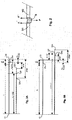
- Figure 2 shows schematically the behavior of the cord of for relatively large sheet thicknesses (several millimeters).
- the surface element is important and the The forces supporting the bath B of metal will therefore be relatively large.
- the movable jaw will be positioned in a gap positive tolerance, which will result in a weld seam slightly recessed, at least on the upper face of the strips M1 and M2 as shown in Figure 2.
- the surface element likely to generate bearing surface tensions of the liquid bath B is very small. he therefore reduce the weight of the bath by reducing the distance between the ends of the two bands M1 and M2. For this, the movable jaw will be positioned in a negative or zero tolerance interval.
- FIGS. 3A and 3B show schematically the relative positions of the ends 13 of the jaw fixed 1 and 23 of the movable jaw 2, after approximation in the welding position.
- FIG. 3A illustrates the case of butt welding of two sheets whose thickness is several millimeters, in a welding machine equipped with shears mechanical guillotine type. These sheets will be reduced later in thickness in a cold rolling mill and so it is im portant that the cord of solder has no extra thickness. Moreover, and given the thickness of the sheets, the bath of liquid metal will be sufficiently fed and the facing faces have a sufficient surface area for it to be supported by superficial tension forces.
- the cutting precision obtained by mechanical shears is ⁇ 0.02 mm.
- the end 23 'of the movable jaw should be removed from the end 13 of the fixed jaw of the distance L1 + L2 but, in because of the uncertainty of ⁇ 0.02 mm on the cut of each of the edges, this distance can be increased or decreased by 0.04 mm, theoretical position 23 ' of the end of the movable jaw then lying between the points 23'a and 23'b on Figure 3A.
- the stroke C of the movable jaw is determined so that the distance L between the ends of the jaws differs from the sum L1 + L2 a pre-set gap e which is positive in the case of relatively thick sheets.
- the preset distance e between the theoretical position 23 'of the end of the jaw mobile and the actual position 23 may therefore be reduced by this tolerance, that is 0.02 mm.
- the end 23 of the movable jaw will then be positioned in a tolerance range leading to an effective play between the edges 10, 20 of the sheets, between a minimum clearance Jmin corresponding to the distance between the points 23'a and 23a and a maximum clearance Jmax corresponding to the distance between points 23'b and 23.
- This type of adjustment can be used, for example for connection hot-rolled steel coils, the thickness of which is between 1 and a few millimeters.
- Such coils are usually connected by butt welding and the weld bead must then be planed because these coils are usually cold-rolled to reduce their thickness and this operation does not support any extra thickness.
- the method of the invention makes it possible to carry out a laser welding much more reliable because it does not require planing, while getting a weld bead of a thickness slightly less than that of connected.
- FIG. 3B illustrates on the contrary the case of very thin sheets, of which the thickness can be only a few tenths of a millimeter, or even a tenth of a millimeter.
- connection of two sheets is made by welding end laser beam in a machine that also cuts the ends of the ban by melting and separation using a laser beam.
- the cutting accuracy is estimated at ⁇ 0.01 millimeter
- the positioning accuracy of the movable jaw with a stop Adjustable mechanical is the same, ie + 0 / + 0.02 mm.
- the ends of the strips M1 and M2 would be held in the jaws S1 and S2 with about 1.5 millimeters for each, and in this case the total dilatation due to the heating of the laser beam would be 0.01 to 0.015 millimeter.
- the theoretical position 23 'of the end of the movable jaw 2 corresponding to a simple edge contact is between points 23'a, 23'b spaced 0.04 mm if the uncertainty on the section is ⁇ 0.01 mm.
- the end 23 thereof will then be positioned in a tolerance interval leading to an effective negative clearance, that is to say, a clamping of the sheets, between a minimum clearance Jmin corresponding to the distance between the points 23 and 23'b and a maximum clearance Jmax corresponding to the distance between points 23a and 23'a.
- the invention makes it possible, by the choice of a positive preset deviation or negative, to obtain, in view of the tolerances, an effective positive or negative adapted to the thickness of the sheets in order to control the thickness of the welding.
- the process can then be completed by measuring the residual space remaining between the ends of the strips M1 and M2 after the positioning of the mobile vehicle S2 and by a modification of the adjustment of the stop.
- the processing carried out downstream requires a quality of the very large welding, which can not be guaranteed by the tolerance range, can then use the inventi on process as a preset and proceed then to a measure of the actual residual clearance between the two ends of the strips M1 and M2 to correct the position of the movable jaw S2 by moving the adjustable mechanical stop of the measured value.
- a stop adjustable by a wedge device on which the movable jaw is applied permanently by the cylinders and, once the race is completed, the device to corners allows you to change the load setting. It is not a question of a new race but a correction of a few hundredths of a millimeter.
- an optical system as described in the patent US 4,854,493 or any other suitable device, magnetic, pneumatic or capacitive.
- the two stops can be regulated independently of one another, it is also possible to measure the effective clearance between the two sheets in two points so as to compensate a defect of parallelism, in the case where one fears a fault of cut, by example in the case of a machine originally equipped with two shears mechanical devices that can see a different alignment.
- the cutting of the ends 1 and 2 of the strips M1 and M2 is done by fusion separation using a laser beam and we use the same laser source for both beams.
- optical guide paths are used and concentration of different beams, which allows to move the cutting beam of the ends according to the plane X1 for the band M1 and according to the X2 plane for the M2 band, and to be able to move the welding beam according to the plane X1 which is then the one in which have placed end to end two bands to be connected.
Landscapes
- Engineering & Computer Science (AREA)
- Physics & Mathematics (AREA)
- Optics & Photonics (AREA)
- Plasma & Fusion (AREA)
- Mechanical Engineering (AREA)
- Laser Beam Processing (AREA)
Applications Claiming Priority (2)
| Application Number | Priority Date | Filing Date | Title |
|---|---|---|---|
| FR0404619A FR2869558B1 (fr) | 2004-04-29 | 2004-04-29 | Procede de reglage de l'epaisseur du cordon de soudure de deux toles metalliques |
| FR0404619 | 2004-04-29 |
Publications (2)
| Publication Number | Publication Date |
|---|---|
| EP1591190A1 true EP1591190A1 (de) | 2005-11-02 |
| EP1591190B1 EP1591190B1 (de) | 2010-06-16 |
Family
ID=34942586
Family Applications (1)
| Application Number | Title | Priority Date | Filing Date |
|---|---|---|---|
| EP05300345A Active EP1591190B1 (de) | 2004-04-29 | 2005-04-29 | Verfahren zum Verschweissen zweier Metallbleche |
Country Status (5)
| Country | Link |
|---|---|
| US (1) | US7820938B2 (de) |
| EP (1) | EP1591190B1 (de) |
| JP (1) | JP5073926B2 (de) |
| DE (1) | DE602005021843D1 (de) |
| FR (1) | FR2869558B1 (de) |
Cited By (4)
| Publication number | Priority date | Publication date | Assignee | Title |
|---|---|---|---|---|
| WO2011131253A1 (fr) | 2010-04-23 | 2011-10-27 | Siemens Vai Metals Technologies Sas | Machine de raboutage de bandes d'acier adaptee au traitement thermique par induction de soudures de raboutage |
| CN105058367A (zh) * | 2015-08-20 | 2015-11-18 | 宁波大学 | 一种四自由度压电微夹钳的制作工艺 |
| CN107234337A (zh) * | 2017-06-27 | 2017-10-10 | 包头钢铁(集团)有限责任公司 | 一种激光焊机焊接低碳钢的方法 |
| CN118385749A (zh) * | 2024-06-26 | 2024-07-26 | 上海信迈电子科技有限公司 | 一种摄像头模组sma马达加工机构及sma马达 |
Families Citing this family (9)
| Publication number | Priority date | Publication date | Assignee | Title |
|---|---|---|---|---|
| JP4470721B2 (ja) * | 2004-12-10 | 2010-06-02 | トヨタ自動車株式会社 | 溶接方法及び溶接整形装置 |
| JP4981419B2 (ja) * | 2006-11-21 | 2012-07-18 | 旭化成イーマテリアルズ株式会社 | 転写装置および転写方法 |
| US8173931B2 (en) * | 2008-06-13 | 2012-05-08 | Electro Scientific Industries, Inc. | Automatic recipe management for laser processing a work piece |
| JP5212632B2 (ja) * | 2008-08-28 | 2013-06-19 | 株式会社Ihi | 溶接加工装置 |
| IT1391660B1 (it) * | 2008-11-10 | 2012-01-17 | Danieli Off Mecc | Sistema di saldatura di nastri metallici |
| KR101220777B1 (ko) | 2010-12-27 | 2013-01-09 | 주식회사 포스코 | 용접 장치 및 용접 방법 |
| KR101360562B1 (ko) | 2011-12-23 | 2014-02-10 | 주식회사 포스코 | 용접장치 및 그의 동작 방법 |
| FR2986170B1 (fr) * | 2012-01-26 | 2014-03-07 | Jfp Microtechnic | Procede et dispositif de soudage, notamment par laser, de fils sur un substrat |
| WO2019157201A1 (en) * | 2018-02-07 | 2019-08-15 | Micro Products Company | Material positioner for welding apparatus and method |
Citations (3)
| Publication number | Priority date | Publication date | Assignee | Title |
|---|---|---|---|---|
| US4626651A (en) * | 1984-02-27 | 1986-12-02 | Kawasaki Steel Corporation | Apparatus for butt welding steel strips by using a laser beam in a steel strip-processing line |
| US4854493A (en) * | 1986-02-28 | 1989-08-08 | Kawasaki Steel Corporation | Method and apparatus for cutting welding steel strips |
| EP0534704A1 (de) * | 1991-09-25 | 1993-03-31 | Toyota Jidosha Kabushiki Kaisha | Verfahren zur Herstellung einer Fahrzeugkarosserieplatte |
Family Cites Families (11)
| Publication number | Priority date | Publication date | Assignee | Title |
|---|---|---|---|---|
| JPS59135886U (ja) * | 1983-02-28 | 1984-09-11 | 川崎製鉄株式会社 | レ−ザ−溶接機 |
| US4935081A (en) * | 1983-03-14 | 1990-06-19 | Becking Paul E | Method for welding of continuous loop ribbon |
| DE3863761D1 (de) * | 1987-11-12 | 1991-08-22 | Tabac Fab Reunies Sa | Verfahren und maschine zum aneinanderfuegen von papierstreifen fuer die ununterbrochene zufuhr an eine maschine, insbesondere fuer die herstellung von zigaretten. |
| DE3920825C2 (de) * | 1989-06-24 | 1995-06-01 | Oxytechnik Ges Systemtech | Vorrichtung zum Beschneiden und Stumpfschweißen von Band- oder Blechrändern mit einer Lasereinrichtung |
| ES2043123T3 (es) * | 1990-01-20 | 1993-12-16 | Thyssen Industrie | Procedimiento y dispositivo para soldar una con otra chapas de acero mediante un procedimiento de soldadura por rayo laser. |
| DE59002571D1 (de) * | 1990-04-06 | 1993-10-07 | Thyssen Industrie | Verfahren zum Aneinanderschweissen von unterschiedlich dicken oder gleich dicken Blechbahnen - auch von dünnen Blechen - durch Laserstrahlschweissen, im Durchlaufverfahren. |
| JP2609379B2 (ja) * | 1991-07-30 | 1997-05-14 | 新日本製鐵株式会社 | 金属板の切断溶接装置 |
| JPH05123878A (ja) * | 1991-11-06 | 1993-05-21 | Kawasaki Steel Corp | 突合せレーザ溶接方法 |
| JPH09216093A (ja) * | 1996-02-08 | 1997-08-19 | Nippon Steel Corp | ビーム溶接設備における突き合わせ間隔調整装置 |
| FR2795356B1 (fr) * | 1999-06-23 | 2001-09-14 | Kvaerner Metals Clecim | Installation de soudage par etincelage |
| US6783052B2 (en) * | 2002-11-21 | 2004-08-31 | Asm Technology Singapore Pte Ltd | Clamp actuation mechanism |
-
2004
- 2004-04-29 FR FR0404619A patent/FR2869558B1/fr not_active Expired - Fee Related
-
2005
- 2005-04-28 JP JP2005132293A patent/JP5073926B2/ja active Active
- 2005-04-29 EP EP05300345A patent/EP1591190B1/de active Active
- 2005-04-29 DE DE602005021843T patent/DE602005021843D1/de active Active
- 2005-05-10 US US11/125,333 patent/US7820938B2/en active Active
Patent Citations (3)
| Publication number | Priority date | Publication date | Assignee | Title |
|---|---|---|---|---|
| US4626651A (en) * | 1984-02-27 | 1986-12-02 | Kawasaki Steel Corporation | Apparatus for butt welding steel strips by using a laser beam in a steel strip-processing line |
| US4854493A (en) * | 1986-02-28 | 1989-08-08 | Kawasaki Steel Corporation | Method and apparatus for cutting welding steel strips |
| EP0534704A1 (de) * | 1991-09-25 | 1993-03-31 | Toyota Jidosha Kabushiki Kaisha | Verfahren zur Herstellung einer Fahrzeugkarosserieplatte |
Cited By (7)
| Publication number | Priority date | Publication date | Assignee | Title |
|---|---|---|---|---|
| WO2011131253A1 (fr) | 2010-04-23 | 2011-10-27 | Siemens Vai Metals Technologies Sas | Machine de raboutage de bandes d'acier adaptee au traitement thermique par induction de soudures de raboutage |
| CN102858488A (zh) * | 2010-04-23 | 2013-01-02 | 西门子奥钢联冶金技术有限公司 | 适合对接焊缝的感应热处理的钢带材对接机 |
| CN105058367A (zh) * | 2015-08-20 | 2015-11-18 | 宁波大学 | 一种四自由度压电微夹钳的制作工艺 |
| CN105058367B (zh) * | 2015-08-20 | 2017-03-01 | 宁波大学 | 一种四自由度压电微夹钳的制作工艺 |
| CN107234337A (zh) * | 2017-06-27 | 2017-10-10 | 包头钢铁(集团)有限责任公司 | 一种激光焊机焊接低碳钢的方法 |
| CN107234337B (zh) * | 2017-06-27 | 2019-03-29 | 包头钢铁(集团)有限责任公司 | 一种激光焊机焊接低碳钢的方法 |
| CN118385749A (zh) * | 2024-06-26 | 2024-07-26 | 上海信迈电子科技有限公司 | 一种摄像头模组sma马达加工机构及sma马达 |
Also Published As
| Publication number | Publication date |
|---|---|
| JP2005313236A (ja) | 2005-11-10 |
| US20050242071A1 (en) | 2005-11-03 |
| FR2869558A1 (fr) | 2005-11-04 |
| US7820938B2 (en) | 2010-10-26 |
| DE602005021843D1 (de) | 2010-07-29 |
| FR2869558B1 (fr) | 2006-09-01 |
| JP5073926B2 (ja) | 2012-11-14 |
| EP1591190B1 (de) | 2010-06-16 |
Similar Documents
| Publication | Publication Date | Title |
|---|---|---|
| EP1591190B1 (de) | Verfahren zum Verschweissen zweier Metallbleche | |
| EP2064023B1 (de) | Vorrichtung und verfahren zur schweissverbindung von bahnenmetallstreifen | |
| EP2964436B1 (de) | Regulierbare anordnung zur umwandlung einer ebenen halterung, kassette, einheit und damit ausgestattete maschine | |
| EP1713610B1 (de) | Klemmwerkzeug, insbesondere lötzange, mit einem ausgleichssystem | |
| EP0640435B1 (de) | Schleifmaschine | |
| EP3016776B1 (de) | Vorrichtung zum verschieben einer anordnung zum schneiden und schweissen von metallbändern ; verfahren zum schneiden und schweissen unter verwendeiner solchen vorrichtung | |
| EP0659518B1 (de) | Anlage zum Aneinanderfügen und zum Schweissen von zwei aufgewickelten Metallbänder mittels eines Laserstrahls um ein kontinuierliches Metallband herzustellen | |
| EP1436114A1 (de) | Verfahren und vorrichtung zum plasmaschneiden mit modulation der von starken bahnänderungen, insbesondere von winkeln abhängigen plasmastrahleigenschaften | |
| EP1749603A1 (de) | Vorrichtung zum Längsteilen von dünnen Bändern | |
| FR3001903A1 (fr) | Installation et procede de laminage | |
| FR2876365A1 (fr) | Procede et dispositif d'enroulement en bobine d'une bande | |
| EP2268445A1 (de) | Zur positionierung eines rads ausgeführte(s) positionsmessverfahren und -vorrichtung | |
| FR2864797A1 (fr) | Machine de planage d'une bande metallique | |
| EP0164802A2 (de) | Vorrichtung zum Herstellen von aus Blech geschweissten Radfelgenrohlingen | |
| EP1638708B1 (de) | Verfahren zur verwaltung einer endloslinienmetallbandverarbeitungsanlage und anlage zur durchführung dieses verfahrens | |
| EP3530404A1 (de) | Vorrichtung und verfahren zur bearbeitung einer extremität eines grundpaneels als vorbereitung auf seine bearbeitung durch reibrührschweissverfahren | |
| FR2651456A1 (fr) | Dispositif de cisaillage-refendage circulaire a froid de toles. | |
| FR2829961A1 (fr) | Procede et machine de soudage de deux films par ultrasons | |
| FR2480652A1 (fr) | Procede et machine pour le soudage ultrasonique de bandes metalliques | |
| EP0781621B1 (de) | Verfahren zum Spleissen von metallischen Bändern und Maschine zur Durchführung des Verfahrens | |
| FR2930463A1 (fr) | Dispositif de fabrication d'un tube helicoidal et procede associe | |
| EP2745976A1 (de) | Vorrichtung zum Verschieben einer Anordnung zum Schweißen von Metallbändern | |
| WO2004059779A1 (fr) | Dispositif de pilotage d’entrainement de films dans un dispositif de realisation d’ensembles multicouches | |
| FR2600919A1 (fr) | Procede et dispositif pour la retouche due a l'usure des cylindres d'un laminoir, sur la ligne de laminage | |
| FR2706793A1 (en) | Process and device for joining cold-rolled steel sheets |
Legal Events
| Date | Code | Title | Description |
|---|---|---|---|
| PUAI | Public reference made under article 153(3) epc to a published international application that has entered the european phase |
Free format text: ORIGINAL CODE: 0009012 |
|
| AK | Designated contracting states |
Kind code of ref document: A1 Designated state(s): AT BE BG CH CY CZ DE DK EE ES FI FR GB GR HU IE IS IT LI LT LU MC NL PL PT RO SE SI SK TR |
|
| AX | Request for extension of the european patent |
Extension state: AL BA HR LV MK YU |
|
| 17P | Request for examination filed |
Effective date: 20060328 |
|
| AKX | Designation fees paid |
Designated state(s): DE ES FR IT |
|
| 17Q | First examination report despatched |
Effective date: 20071129 |
|
| RAP1 | Party data changed (applicant data changed or rights of an application transferred) |
Owner name: SIEMENS VAI METALS TECHNOLOGIES SAS |
|
| GRAP | Despatch of communication of intention to grant a patent |
Free format text: ORIGINAL CODE: EPIDOSNIGR1 |
|
| GRAS | Grant fee paid |
Free format text: ORIGINAL CODE: EPIDOSNIGR3 |
|
| GRAA | (expected) grant |
Free format text: ORIGINAL CODE: 0009210 |
|
| AK | Designated contracting states |
Kind code of ref document: B1 Designated state(s): DE ES FR IT |
|
| REF | Corresponds to: |
Ref document number: 602005021843 Country of ref document: DE Date of ref document: 20100729 Kind code of ref document: P |
|
| PG25 | Lapsed in a contracting state [announced via postgrant information from national office to epo] |
Ref country code: IT Free format text: LAPSE BECAUSE OF FAILURE TO SUBMIT A TRANSLATION OF THE DESCRIPTION OR TO PAY THE FEE WITHIN THE PRESCRIBED TIME-LIMIT Effective date: 20100616 |
|
| PLBE | No opposition filed within time limit |
Free format text: ORIGINAL CODE: 0009261 |
|
| STAA | Information on the status of an ep patent application or granted ep patent |
Free format text: STATUS: NO OPPOSITION FILED WITHIN TIME LIMIT |
|
| 26N | No opposition filed |
Effective date: 20110317 |
|
| REG | Reference to a national code |
Ref country code: DE Ref legal event code: R097 Ref document number: 602005021843 Country of ref document: DE Effective date: 20110316 |
|
| PG25 | Lapsed in a contracting state [announced via postgrant information from national office to epo] |
Ref country code: ES Free format text: LAPSE BECAUSE OF FAILURE TO SUBMIT A TRANSLATION OF THE DESCRIPTION OR TO PAY THE FEE WITHIN THE PRESCRIBED TIME-LIMIT Effective date: 20100927 |
|
| REG | Reference to a national code |
Ref country code: FR Ref legal event code: PLFP Year of fee payment: 11 |
|
| REG | Reference to a national code |
Ref country code: DE Ref legal event code: R082 Ref document number: 602005021843 Country of ref document: DE Representative=s name: FISCHER, MICHAEL, DR., DE Ref country code: DE Ref legal event code: R081 Ref document number: 602005021843 Country of ref document: DE Owner name: PRIMETALS TECHNOLOGIES FRANCE SAS, FR Free format text: FORMER OWNER: SIEMENS VAI METALS TECHNOLOGIES SAS, SAINT CHAMOND, FR Ref country code: DE Ref legal event code: R082 Ref document number: 602005021843 Country of ref document: DE Representative=s name: KINNSTAETTER, KLAUS, DIPL.-PHYS.UNIV., DE |
|
| REG | Reference to a national code |
Ref country code: FR Ref legal event code: CD Owner name: PRIMETALS TECNOLOGIES FRANCE SAS, FR Effective date: 20160107 |
|
| REG | Reference to a national code |
Ref country code: FR Ref legal event code: PLFP Year of fee payment: 12 |
|
| REG | Reference to a national code |
Ref country code: DE Ref legal event code: R082 Ref document number: 602005021843 Country of ref document: DE Representative=s name: KINNSTAETTER, KLAUS, DIPL.-PHYS.UNIV., DE |
|
| REG | Reference to a national code |
Ref country code: FR Ref legal event code: PLFP Year of fee payment: 13 |
|
| REG | Reference to a national code |
Ref country code: FR Ref legal event code: PLFP Year of fee payment: 14 |
|
| REG | Reference to a national code |
Ref country code: DE Ref legal event code: R082 Ref document number: 602005021843 Country of ref document: DE Representative=s name: KINNSTAETTER, KLAUS, DIPL.-PHYS.UNIV., DE Ref country code: DE Ref legal event code: R081 Ref document number: 602005021843 Country of ref document: DE Owner name: CLECIM SAS, FR Free format text: FORMER OWNER: PRIMETALS TECHNOLOGIES FRANCE SAS, SAVIGNEUX, FR |
|
| PGFP | Annual fee paid to national office [announced via postgrant information from national office to epo] |
Ref country code: DE Payment date: 20240418 Year of fee payment: 20 |
|
| PGFP | Annual fee paid to national office [announced via postgrant information from national office to epo] |
Ref country code: FR Payment date: 20240426 Year of fee payment: 20 |