EP1589729A2 - Tragbares elektronisches Gerät - Google Patents
Tragbares elektronisches Gerät Download PDFInfo
- Publication number
- EP1589729A2 EP1589729A2 EP05008179A EP05008179A EP1589729A2 EP 1589729 A2 EP1589729 A2 EP 1589729A2 EP 05008179 A EP05008179 A EP 05008179A EP 05008179 A EP05008179 A EP 05008179A EP 1589729 A2 EP1589729 A2 EP 1589729A2
- Authority
- EP
- European Patent Office
- Prior art keywords
- portable device
- sound
- speaker
- speakers
- user
- Prior art date
- Legal status (The legal status is an assumption and is not a legal conclusion. Google has not performed a legal analysis and makes no representation as to the accuracy of the status listed.)
- Withdrawn
Links
Images


Classifications
-
- H—ELECTRICITY
- H04—ELECTRIC COMMUNICATION TECHNIQUE
- H04M—TELEPHONIC COMMUNICATION
- H04M1/00—Substation equipment, e.g. for use by subscribers
- H04M1/02—Constructional features of telephone sets
- H04M1/03—Constructional features of telephone transmitters or receivers, e.g. telephone hand-sets
-
- H—ELECTRICITY
- H04—ELECTRIC COMMUNICATION TECHNIQUE
- H04M—TELEPHONIC COMMUNICATION
- H04M1/00—Substation equipment, e.g. for use by subscribers
- H04M1/02—Constructional features of telephone sets
- H04M1/0202—Portable telephone sets, e.g. cordless phones, mobile phones or bar type handsets
- H04M1/0206—Portable telephones comprising a plurality of mechanically joined movable body parts, e.g. hinged housings
- H04M1/0208—Portable telephones comprising a plurality of mechanically joined movable body parts, e.g. hinged housings characterized by the relative motions of the body parts
- H04M1/0214—Foldable telephones, i.e. with body parts pivoting to an open position around an axis parallel to the plane they define in closed position
Definitions
- This disclosure teaches a technique relating to a portable device which can provide higher quality of sound during the reproduction of music.
- Speakers are used in portable terminals such as a mobile phone, a PHS (Personal Handy phone System), and a PDA (Personal Data Assistance, Personal Data Assistants), for outputting an electronic sound for ringing.
- portable terminals such as a mobile phone, a PHS (Personal Handy phone System), and a PDA (Personal Data Assistance, Personal Data Assistants), for outputting an electronic sound for ringing.
- PHS Personal Handy phone System
- PDA Personal Data Assistance, Personal Data Assistants
- portable terminals have a function of reproducing music and outputting the reproduced music via speakers.
- Applications such as games on mobile terminals, achieve high quality by using a screen display on a liquid crystal display and speakers that output sounds relating to the applications.
- portable terminals are equipped with two or more speakers that output a stereophonic sound or a surround sound for reproducing music, providing a higher quality of sound, for example, the ringing sound.
- speakers can be mounted only in limited portions of those portable terminals.
- speakers are disposed on an opposite side of a portable terminal from a surface where a key button for manipulating the portable terminal is disposed. Accordingly, sounds are output from the speakers on the back side of the portable terminal, thus a high quality surround effect or a high quality stereophonic effect can not be achieved for music that is used in operating applications such as games.
- speakers can not be disposed on the portable terminal sufficiently apart from each other, providing an insufficient stereophonic effect or surround sound effect for outputting sounds.
- the stereophonic effect or surround sound effect can be improved by putting an object, such as a finger of the user of the portable terminal, between at least two speakers.
- an object such as a finger of the user of the portable terminal
- This disclosure teaches techniques for solving the problem described above and by providing a portable device which has a structure that enhances stereophonic or surround sound effects.
- a portable device comprises, a plurality of speakers which output a stereophonic sound or a surround sound.
- the plurality of speakers are separated into at least two groups of speaker, and the at least two groups of speakers are positioned apart from each other.
- the portable device further comprises an object which is positioned between the at least two groups of speaker.
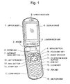
- Fig. 1 illustrates an external appearance of a mobile phone according to an exemplary embodiment.
- Fig. 2 illustrates a configuration of a main part of the portable phone according to the exemplary embodiment.
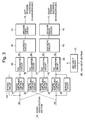
- Fig. 3 illustrates a music output section of the portable phone according to the exemplary embodiment.
- Fig. 4 illustrates an operation for generating stereophonic sounds and surround sounds in the portable phone of the exemplary embodiment.
- a portable device comprises a plurality of speakers.
- the speakers output surround sound or stereophonic sound.
- the speakers are divided into at least two groups.
- the groups of speakers are disposed on the portable device apart from each other.
- an object is disposed between the at least two groups of speakers. Accordingly, the object can act as a shield among the groups of speakers, thereby increasing a difference in phases and/or amplitudes of sounds from the speakers. This enhances a surround effect or a stereophonic effect recognized by a user of the portable device.
- a plurality of speakers separated into two groups are disposed on both sides on the same body surface of the portable terminal.
- a portion where the user is likely to place a finger when using the mobile terminal is interposed between the two groups of speakers.
- the terminal is driven so as to output stereophonic sound or surround sound through the two groups of speakers.
- Figs. 1 to 4 illustrates only portions which are necessary for explaining the exemplary embodiment.
- the portable terminal of this exemplary embodiment comprises an upper body 1, a lower body 2, and a hinge 3.
- the upper body 1 and the lower body 2 are pivotally and electrically coupled by the hinge 3 .
- the upper body 1 and the lower body 2 are folded by pivoting on hinge 3 such that a front surface of the upper body 1 and a front surface for the lower body 2 face each other.
- the portable terminal receives wireless signal from a networks.
- Front surface of the upper body 1 comprises a black-and-white or color display part 4, and upper and lower receivers 5 and 6.
- the display 4 has a liquid crystal panel or organic EL (Electronic Luminescence) panel for displaying various kinds of information.
- the upper and lower receivers 5 and 6 output sounds received via the wireless signal.
- Front surface of the lower body 2 comprises an Internet mode button 7 for selecting an operating state in an Internet mode, a menu button 8 for displaying and selecting functions or operation modes, an enter key 9 for confirming a selected function or operation modes, a mail button 10 for selecting a mail creation mode and so on, a telephone book button 11 for displaying registered telephone numbers, a start key 12 for starting a designated operating state, a clear key 13 for aborting a designated operating state, an end key 14 for terminating transmission and reception of signals via the wireless signals, a ten key 15 composed of numbers 0 to 9 and symbols # and * for inputting telephone numbers and characters for composing mails, a left speaker 16 and a right speaker 17 for outputting reproduced music, a microphone 18 for inputting sounds, a four-way key 19 for scrolling options on the display 4 and performing operations of games on the display 4.
- the left speaker 16 and the right speaker 17 are separately disposed on a right and a left side on a surface of the lower body 2.
- the four-way key 19 is interposed between the speakers 16 and 17.
- the electrical configuration of the main part comprises the display part 4, the left speaker 16, the right speaker 17, a control section 21, a transmission/reception section 22, a storage section 23, a music reproduction section 24, a music output section 25, and a key input section 26.
- the display part 4, the left speaker 16, and the right speaker 17 are the same as those described in Fig. 1.
- the control section 21 comprises a CPU (Central Processing Unit), controls the overall operations of the portable terminal.
- the control section 21 converts a sound signal received from the microphone 18 into digital transmission data and supplies the digital transmission data to the transmission/reception section 22.
- the control section 21 receives digital reception data from the transmission/reception section 22, converts the digital reception data into an analog signal and supplies the analog signal to the receivers 5 and 6.
- the control section 21 retrieves data stored in the storage section 23 and outputs the retrieved data to the music output section 25.
- the transmission/reception section 22 converts, the digital transmission data received from the control section 21 into a radio signal, , and supplies the radio signal to an antenna (not shown). In addition, The transmission /reception section 22 converts a radio signal received from the antenna (not shown) into the reception digital data, and outputs the reception digital data to the control section 21.
- the storage section 23 is comprises a ROM (Read Only Memory) and stores data such as music.
- the music reproduction section 24 converts the data inputted from the control section 21 through the music output section 25 into music data and outputs, to the music output section 25, the converted sound data such as, stereophonic sound data, and surround sound data.
- the music output section 25 drives the left speaker 16 and the right speaker 17 according to the sound data received from the music reproduction section 24 or surround sound data.
- the surround data may be generated from the stereophonic data.
- the key input section 26 In response to a key operation on the body surface, the key input section 26 generates and outputs a signal for controlling the operations of the music output section 25.
- the music output section 25 of this embodiment comprises the left speaker 16, the right speaker 17, phase/amplitude control circuits 31 to 34, digital/analog (D/A) converter circuits 35 to 38, synthetic circuits 39 and 40, speaker drive circuits 41 and 42, a key input circuit 43, and bypass circuits 44 and 45.
- the speakers 16 and 17 are the same as those described in Fig. 2.
- the phase/amplitude control circuits 31 and 33 adjust the phase and amplitude of the stereophonic sound data and output the adjusted stereophonic sound data to the respective D/A converters 35 and 37.
- the phase/amplitude control circuits 32 and 34 adjust the phase and amplitude of the stereophonic sound data and output the adjusted data to the respective D/A converters 35 and 37.
- the D/A converter circuits 35 to 38 convert digital sound signals (adjusted sound data) received from the phase/amplitude control circuits 31 to 34 into analog sound signals, respectively, and output the analog signals S1 to S4 to the respective synthetic circuits 39 and 40.
- the synthetic circuit 39 synthesizes the analog signals S1 and S4 from the respective D/A converter 35 and 36 and outputs the synthesized signal to the speaker drive circuit 41.
- the synthetic circuit 40 synthesizes the analog signals S3 and S2 from the respective D/A converter 37 and 38 and outputs the synthesized signal to the speaker driver circuit 42.
- the speaker drive circuits 41 and 42 amplify the synthesized signals from the synthetic respective circuits 39 and 40, and supply the amplified signals to the left speaker 16 and the right speaker 17, respectively.
- the key input circuit 43 In response to an input from the key input section 26, the key input circuit 43 generates and output a signal for controlling the operating states of the phase/amplitude control circuits 31 to 34 and the bypass circuits 44 and 45.
- the bypass circuits 44 and 45 get stereophonic sound data M1 and M2 go directly into the respective D/A converter 35 and 38 without going though the respective phase/amplitude control circuit if controlled to do so.
- Fig. 4 explains an operation of generating the stereophonic sounds and the surround sounds in the portable terminal of this exemplary embodiment. Referring to Figs. 1 to 4, the process of generating stereophonic sounds will be first discussed below.
- the portable terminal of this exemplary embodiment when music or sounds including call reception melodies and melodies for sound effects in games are to be generated as stereophonic sounds, for example, a user of the portable terminal presses the menu button 8 on the front of the body and selects various operation modes displayed on a display screen of the display part 4. In addition, the user selects a stereophonic sound mode from the modes displayed on the display screen by manipulating the four-way key 19 and confirms the selection by pressing the enter key 9.
- the key input section 26 receives the selection and controls the key input circuit 43, so that the key input circuit 43 generates and outputs a signal to disable an operations of the phase/amplitude control circuits 31 to 34 and to enable an operations of the bypass circuits 44 and 45. That is, the key input circuit 43 makes stereophonic sound data M1 and M2 go directly into the respective D/A converter 35 and 38 without going though the respective phase/amplitude control circuit.
- the control section 21 upon receiving specific music data from the storage section 23 according to a detection of a call reception and a progress of a game, the control section 21 outputs the music data to the music reproduction section 24 via the music output section 25.
- the music reproduction section 24 generates the stereophonic sound data M1 and M2 according to the music data received from the music output section 21 and returns the stereophonic sound data M1 and M2 to the music output section 25.
- the stereophonic sound data M1 and M2 are input to the D/A converter circuits 35 and 38 via the bypass circuits 44 and 45, respectively. Accordingly the D/A converter circuit 35 and 38 outputs the respective analog sound signals S1 and S2 to the respective synthetic circuits 39 and 40.
- the synthetic circuit 39 amplifies the analog sound signal S1 and outputs the amplified signal S1 to the speaker drive circuit 41.
- the synthetic circuit 40 amplifies the analog sound signal S2 and outputs the amplified signal S2 to the speaker drive circuit 42.
- the speaker drive circuits 41 and 42 receives the amplified signals S1 and S2 from the respective synthetic circuits 39 and 40 and outputs the signals received from the synthetic circuits 39 and 40 to the left speaker 16 and the right speaker 17, respectively.
- the left speaker and right speaker outputs respective sounds P1 and P2 based on the signals S1 and S2 from the respective synthetic circuits 41 and 42.
- the sounds P1 and P2 propagates to a left ear 51 and a right ear 52 of the user 53 of the portable terminal, respectively, so that the user 53 can recognize sounds from the portable terminal as sounds with a stereophonic effect.
- a user of the portable terminal presses the menu button 8 on the front of the body and the various operation modes are displayed on a display screen of the display part 4.
- the user selects a surround sound mode from the modes displayed on the display screen by manipulating the four-way key 19 and confirms the selection by pressing the enter key 9.
- the key input section 26 receives the selection and controls the key input circuit 43, so that the key input circuit 43 generates and outputs a signal to enable an operations of the phase/amplitude control circuits 31 to 34 and to disable an operations of the bypass circuits 44 and 45.
- the control section 21 outputs the music data to the music reproduction section 24 via the music output section 25.
- the music reproduction section 24 generates the stereophonic sound data M1 and M2 according to the music data received from the music output section 21 and returns the stereophonic sound data M1 and M2 to the music output section 25.
- the stereophonic sound data M1 is input to the phase/amplitude control circuits 31 and 33.
- the stereophonic sound data M2 is input to the phase/amplitude control circuits 32 and 34.
- the phase/amplitude control circuits 31 and 33 adjust phases and amplitudes of the stereophonic sound data M1 and output the adjusted data to respective the D/A converters 35 and 37.
- the phase/amplitude control circuits 32 and 34 adjust phases and amplitudes of the stereophonic sound data M2 and output the adjusted data to the respective D/A converters 36 and 38.
- the D/A converter circuits 35 and 36 convert the adjusted digital data received from the phase/amplitude control circuits 31 and 32 into analog sound signals S1 and S4, respectively, and outputs the respective analog sound signals S1 and S4 to the synthetic circuit 39.
- the D/A converter circuits 37 and 38 convert the adjusted digital data received from the phase/amplitude control circuits 33 and 34 into analog sound signals S3 and S2, respectively, and outputs the respective analog sound signals S3 and S2 to the synthetic circuit 40.
- the music reproduction section 24 may generate surrounding sounds data comprising three or more different data.
- the music output section 25 outputs the three or more data to the phase/amplitude control circuits 31 to 34.
- the phase/amplitude control circuits 31 to 34 adjust phases and amplitudes of the respective sound data received from the music output section 25 and output the adjusted data to the respective D/A converters 35 to 38.
- the D/A converter circuits 35 to 38 convert the respective adjusted digital data received from the phase/amplitude control circuits 31 to 34 into analog sound signals, and outputs the analog sound signals to the respective synthetic circuits 39 and 40.
- the synthetic circuit 39 synthesizes the analog sound signal S1 and S4 received from the respective D/A converter circuits 35 and 36 and output the synthesized signal (S1 + S4) to the speaker drive circuit 41.
- the speaker drive circuit 41 amplifies the synthesized (S1 + S4) and outputs the amplified signal (S1 + S4) to the left speaker 16. Accordingly the left speaker 16 outputs a sound P1 based on the analog sound signal S1 and outputs a sound P4 based on the analog sound signal S4.
- the synthetic circuit 40 synthesizes the analog sound signal S3 and S2 received from the respective D/A converter circuits 37 and 38 and outputs the synthesized signal (S2 + S3) to the speaker drive circuit 41.
- the speaker drive circuit 42 amplifies the synthesized (S2 + S3) and outputs the amplified signal (S2 + S3) to the right speaker 17. Accordingly the right speaker 17 outputs a sound P2 based on the analog sound signals S2 and outputs a sound P3 based on the analog sound signal S3.
- the sound P1 from the left speaker 16 and the sound P3 from the right speaker 17 are spatially synthesized and propagated to the left ear 51 of the user 53
- the sound P4 from the left speaker 16 and the sound P2 from the right speaker 17 are spatially synthesized and propagated to the right ear 52 of the user 53. Accordingly, the user 53 can recognize sounds from the potable terminal with a surround effect
- sounds from the left speaker 16 and the right speaker 17 propagate through a space and reach the ears of the user 53.
- the sounds from the speakers 16 and 17 reach the left ear 51 and the right ear 52 of the user 53 through different paths than each other, the user 53 hears a sound with a surround effect due to a difference in phase and amplitude among the sounds P1 to P4.
- the user 53 recognizes a small surround or stereophonic effect.
- at least one key such as the four-way key for manipulating the portable terminal is positioned between the speakers 16 and 17 providing a shield, such as a finger of the user 53, between the speakers 16 and 17.
- the phase difference and the amplitude difference among the sounds P1 to P4 can be enlarged, thereby enhancing the surround effect recognized by the user 53.
- both sounds with stereophonic effects and sound with surround effects can be selectively heard by using music or sound data stored in the storage section 23, even if the stored data is monophonic music or sound data.
- the left speaker 16 and the right speaker 17 are separately disposed on a left side and a right side on a surface of a body panel, and the four-way key 19 is interposed between the speakers.
- the user's finger on the four-way key 19 can be a shield which increases the isolation between the speakers 16 and 17, so that a phase difference and an amplitude difference can become definite between the sounds P1 and P3 to the left ear 51 and a phase difference and an amplitude difference can become definite between the sounds P2 and P4 to the right ear 52. Accordingly, it is possible to achieve an enhanced stereophonic effect or an enhanced surround effect.
- the exemplary embodiment described a foldable mobile phone as an example of the portable terminal.
- any portable device can be used regardless of its shape and structure as long as an object or a portion to be a shield, such as key manipulated by a user of the terminal device, is interposed between the speakers.
- the four-way key on which the user is likely to place a finger when using the portable terminal is disposed as a portion or an object to be a shield between the left speaker and the right speaker.
- the portion or the object to be a shield can be other keys than the four-way key, and can be a structure other than key.
- the number of speakers is not limited to two. Any number of speakers may be divided into a plurality of groups and disposed on a portable device according to the technique disclosed. Also, the number of synthetic circuit and the number of the speaker driver may be three or more according to the number of the speakers.. In addition, the number of the plurality of groups of speaker is not limited to two.
- the number of phase/amplitude control circuits may be five or more.
- the number of the D/A converter circuit may be five or more according to the number of the phase/amplitude control circuits.
- the technique disclosed is applicable not only to existing portable devices such as a mobile phone, a PHS, and a PDA but also to various kinds of upcoming compact portable equipment having the function of reproducing music.
Landscapes
- Engineering & Computer Science (AREA)
- Signal Processing (AREA)
- Stereophonic System (AREA)
- Telephone Function (AREA)
- Stereophonic Arrangements (AREA)
- Circuit For Audible Band Transducer (AREA)
- Telephone Set Structure (AREA)
Applications Claiming Priority (2)
| Application Number | Priority Date | Filing Date | Title |
|---|---|---|---|
| JP2004122865A JP2005311501A (ja) | 2004-04-19 | 2004-04-19 | 携帯端末装置 |
| JP2004122865 | 2004-04-19 |
Publications (2)
| Publication Number | Publication Date |
|---|---|
| EP1589729A2 true EP1589729A2 (de) | 2005-10-26 |
| EP1589729A3 EP1589729A3 (de) | 2006-12-13 |
Family
ID=34935172
Family Applications (1)
| Application Number | Title | Priority Date | Filing Date |
|---|---|---|---|
| EP05008179A Withdrawn EP1589729A3 (de) | 2004-04-19 | 2005-04-14 | Tragbares elektronisches Gerät |
Country Status (4)
| Country | Link |
|---|---|
| US (1) | US20050249373A1 (de) |
| EP (1) | EP1589729A3 (de) |
| JP (1) | JP2005311501A (de) |
| CN (1) | CN1691699A (de) |
Cited By (2)
| Publication number | Priority date | Publication date | Assignee | Title |
|---|---|---|---|---|
| WO2011017124A3 (en) * | 2009-07-27 | 2011-05-05 | Qualcomm Incorporated | M-s stereo reproduction at a device |
| US9661412B2 (en) | 2011-06-20 | 2017-05-23 | Nokia Technologies Oy | Apparatus for providing passive stereo amplification for a portable device |
Families Citing this family (9)
| Publication number | Priority date | Publication date | Assignee | Title |
|---|---|---|---|---|
| JP5138911B2 (ja) * | 2006-08-29 | 2013-02-06 | 京セラ株式会社 | 携帯電話機 |
| US8209609B2 (en) * | 2008-12-23 | 2012-06-26 | Intel Corporation | Audio-visual search and browse interface (AVSBI) |
| WO2011088707A1 (en) * | 2010-01-21 | 2011-07-28 | Design Pool Limited | A multi-functional wireless device |
| US8542854B2 (en) * | 2010-03-04 | 2013-09-24 | Logitech Europe, S.A. | Virtual surround for loudspeakers with increased constant directivity |
| US9264813B2 (en) * | 2010-03-04 | 2016-02-16 | Logitech, Europe S.A. | Virtual surround for loudspeakers with increased constant directivity |
| CN104238990B (zh) * | 2013-06-14 | 2021-09-14 | 联想(北京)有限公司 | 一种电子设备及音频输出方法 |
| CN104464763A (zh) * | 2013-09-25 | 2015-03-25 | 联想(北京)有限公司 | 一种信息处理方法及装置 |
| KR102226420B1 (ko) * | 2013-10-24 | 2021-03-11 | 삼성전자주식회사 | 다채널 오디오 신호 생성 방법 및 이를 수행하기 위한 장치 |
| CN104936090B (zh) * | 2015-05-04 | 2018-12-14 | 联想(北京)有限公司 | 一种音频数据的处理方法和音频处理器 |
Citations (3)
| Publication number | Priority date | Publication date | Assignee | Title |
|---|---|---|---|---|
| EP1124175A2 (de) * | 2000-02-08 | 2001-08-16 | Nokia Corporation | Anzeigegerät |
| WO2004012068A1 (en) * | 2002-07-25 | 2004-02-05 | Sonion Horsens A/S | Mobile handset and assembly having multi-loudspeaker system |
| US20040023697A1 (en) * | 2000-09-27 | 2004-02-05 | Tatsumi Komura | Sound reproducing system and method for portable terminal device |
Family Cites Families (1)
| Publication number | Priority date | Publication date | Assignee | Title |
|---|---|---|---|---|
| JP2004056408A (ja) * | 2002-07-19 | 2004-02-19 | Hitachi Ltd | 携帯電話端末 |
-
2004
- 2004-04-19 JP JP2004122865A patent/JP2005311501A/ja active Pending
-
2005
- 2005-04-14 EP EP05008179A patent/EP1589729A3/de not_active Withdrawn
- 2005-04-15 US US11/106,632 patent/US20050249373A1/en not_active Abandoned
- 2005-04-19 CN CNA200510066020XA patent/CN1691699A/zh active Pending
Patent Citations (3)
| Publication number | Priority date | Publication date | Assignee | Title |
|---|---|---|---|---|
| EP1124175A2 (de) * | 2000-02-08 | 2001-08-16 | Nokia Corporation | Anzeigegerät |
| US20040023697A1 (en) * | 2000-09-27 | 2004-02-05 | Tatsumi Komura | Sound reproducing system and method for portable terminal device |
| WO2004012068A1 (en) * | 2002-07-25 | 2004-02-05 | Sonion Horsens A/S | Mobile handset and assembly having multi-loudspeaker system |
Cited By (2)
| Publication number | Priority date | Publication date | Assignee | Title |
|---|---|---|---|---|
| WO2011017124A3 (en) * | 2009-07-27 | 2011-05-05 | Qualcomm Incorporated | M-s stereo reproduction at a device |
| US9661412B2 (en) | 2011-06-20 | 2017-05-23 | Nokia Technologies Oy | Apparatus for providing passive stereo amplification for a portable device |
Also Published As
| Publication number | Publication date |
|---|---|
| US20050249373A1 (en) | 2005-11-10 |
| EP1589729A3 (de) | 2006-12-13 |
| CN1691699A (zh) | 2005-11-02 |
| JP2005311501A (ja) | 2005-11-04 |
Similar Documents
| Publication | Publication Date | Title |
|---|---|---|
| EP1589729A2 (de) | Tragbares elektronisches Gerät | |
| CN1469618A (zh) | 蜂窝电话终端 | |
| JPWO2008010510A1 (ja) | 携帯端末 | |
| US7668324B2 (en) | Folding electronic device | |
| US7962184B2 (en) | Method and apparatus for controlling bar-type mobile terminal having dual display unit | |
| US20080150907A1 (en) | Touch screen-enabled mobile terminal and function display method for the same | |
| JP3159467U (ja) | 伴奏機能を有する携帯装置 | |
| JP5037599B2 (ja) | 携帯用電子機器 | |
| US20040203975A1 (en) | Remote control for a cellular phone | |
| KR100594015B1 (ko) | 휴대폰의 보조 표시부 구동 제어장치 및 방법 | |
| JPH11252216A (ja) | 電話機 | |
| JP2004096573A (ja) | 折り畳み式携帯電話機 | |
| EP4418642A1 (de) | Audioverarbeitungsverfahren und elektronische vorrichtung | |
| KR20030028018A (ko) | 노래방 기능이 장착된 핸드폰 | |
| JP4246451B2 (ja) | 携帯電話機 | |
| KR20100001586A (ko) | 4극 이어폰 및 이와 연결되는 휴대 단말기 | |
| JP5384194B2 (ja) | 表示制御デバイス、表示制御方法、情報処理装置、表示制御プログラム、および該プログラムを記録した記録媒体 | |
| JP2008059009A (ja) | 携帯端末およびそのユーザモード設定方法 | |
| JP3459587B2 (ja) | 電話装置 | |
| JP2002261884A (ja) | 移動通信端末 | |
| KR100925424B1 (ko) | 음량 및 진동량 조절 기능을 갖는 이동 단말기 | |
| KR200453089Y1 (ko) | 라디오 수신기 | |
| JPH11243442A (ja) | 多機能電話機 | |
| KR101061820B1 (ko) | 휴대용 스피커 시스템으로 활용 가능한 이동통신 단말기 | |
| JP2003198711A (ja) | 移動体電話機 |
Legal Events
| Date | Code | Title | Description |
|---|---|---|---|
| PUAI | Public reference made under article 153(3) epc to a published international application that has entered the european phase |
Free format text: ORIGINAL CODE: 0009012 |
|
| AK | Designated contracting states |
Kind code of ref document: A2 Designated state(s): AT BE BG CH CY CZ DE DK EE ES FI FR GB GR HU IE IS IT LI LT LU MC NL PL PT RO SE SI SK TR |
|
| AX | Request for extension of the european patent |
Extension state: AL BA HR LV MK YU |
|
| PUAL | Search report despatched |
Free format text: ORIGINAL CODE: 0009013 |
|
| AK | Designated contracting states |
Kind code of ref document: A3 Designated state(s): AT BE BG CH CY CZ DE DK EE ES FI FR GB GR HU IE IS IT LI LT LU MC NL PL PT RO SE SI SK TR |
|
| AX | Request for extension of the european patent |
Extension state: AL BA HR LV MK YU |
|
| 17P | Request for examination filed |
Effective date: 20061128 |
|
| AKX | Designation fees paid |
Designated state(s): DE FR GB IT |
|
| 17Q | First examination report despatched |
Effective date: 20090904 |
|
| STAA | Information on the status of an ep patent application or granted ep patent |
Free format text: STATUS: THE APPLICATION HAS BEEN WITHDRAWN |
|
| 18W | Application withdrawn |
Effective date: 20100107 |