EP1589613A1 - Antennenverstärker mit den Steckverbindungen zwischen Antennenverstärker und elektrischen Leitungen - Google Patents
Antennenverstärker mit den Steckverbindungen zwischen Antennenverstärker und elektrischen Leitungen Download PDFInfo
- Publication number
- EP1589613A1 EP1589613A1 EP05008730A EP05008730A EP1589613A1 EP 1589613 A1 EP1589613 A1 EP 1589613A1 EP 05008730 A EP05008730 A EP 05008730A EP 05008730 A EP05008730 A EP 05008730A EP 1589613 A1 EP1589613 A1 EP 1589613A1
- Authority
- EP
- European Patent Office
- Prior art keywords
- signal processing
- processing unit
- slot
- antenna amplifier
- plug
- Prior art date
- Legal status (The legal status is an assumption and is not a legal conclusion. Google has not performed a legal analysis and makes no representation as to the accuracy of the status listed.)
- Withdrawn
Links
- 239000004020 conductor Substances 0.000 title claims abstract description 14
- 238000009434 installation Methods 0.000 description 2
- 238000004891 communication Methods 0.000 description 1
- 238000010276 construction Methods 0.000 description 1
Images


Classifications
-
- H—ELECTRICITY
- H01—ELECTRIC ELEMENTS
- H01R—ELECTRICALLY-CONDUCTIVE CONNECTIONS; STRUCTURAL ASSOCIATIONS OF A PLURALITY OF MUTUALLY-INSULATED ELECTRICAL CONNECTING ELEMENTS; COUPLING DEVICES; CURRENT COLLECTORS
- H01R13/00—Details of coupling devices of the kinds covered by groups H01R12/70 or H01R24/00 - H01R33/00
- H01R13/64—Means for preventing incorrect coupling
-
- H—ELECTRICITY
- H01—ELECTRIC ELEMENTS
- H01R—ELECTRICALLY-CONDUCTIVE CONNECTIONS; STRUCTURAL ASSOCIATIONS OF A PLURALITY OF MUTUALLY-INSULATED ELECTRICAL CONNECTING ELEMENTS; COUPLING DEVICES; CURRENT COLLECTORS
- H01R2201/00—Connectors or connections adapted for particular applications
-
- H—ELECTRICITY
- H01—ELECTRIC ELEMENTS
- H01R—ELECTRICALLY-CONDUCTIVE CONNECTIONS; STRUCTURAL ASSOCIATIONS OF A PLURALITY OF MUTUALLY-INSULATED ELECTRICAL CONNECTING ELEMENTS; COUPLING DEVICES; CURRENT COLLECTORS
- H01R2201/00—Connectors or connections adapted for particular applications
- H01R2201/26—Connectors or connections adapted for particular applications for vehicles
Definitions
- the invention relates to a signal processing unit, in particular a Antenna amplifier, of a vehicle according to the features of the preamble of claim 1.
- antenna amplifiers for Vehicles are used for the production of electrical connections Normally used multipolar connectors, which can be locked, for example are. In this case, such connectors take up much space.
- antenna conductor structures For the Connection to a vehicle-side electrical line and for the connection to the arranged on the vehicle window, for example, antenna conductor structures Several separate connectors are used.
- the Signal processing unit according to the number of existing connectors each separate slots on. This variety of separate slots, which are usually designed differently, leads to a increased space requirement on the circuit board of the antenna amplifier and thus an unnecessary increase in the respective device (see Figure 3).
- the Assembly of such connectors on the part of the signal processing unit is associated with increased effort, resulting in higher installation costs.
- multiple connectors are very expensive, resulting in Increasing the cost of the antenna amplifier leads.
- the invention is therefore based on the object, a signal processing unit to provide, with which the described disadvantages are avoided.
- the housing of the signal processing Unit has an opening in which a single slot is arranged or from which a lead to the single slot (4) is led out, wherein the electrical lines via at least one corresponding connector can be connected to the slot in the signal processing unit.
- the space required in the signal processing unit above all on the board, reduce.
- the assembly time is reduced, and the design of the housing or the printed circuit board simplified, so that in total the system costs (signal processing unit and its components, plug connections and lines) are significantly reduced.
- Even after the later Mounting the signal processing unit in the vehicle is a faster Contacting, i. Connection of the unit to the electrical lines, Given, as a rule, no longer several plugs or sockets with several Slots in the signal processing unit are brought together but these can be plugged into the single slot.
- At least one of the lines connects the signal processing unit with an antenna conductor structure of the vehicle and / or with a vehicle-side line. So is done over the only one Slot and a single line or multiple lines with a single Plug (or socket) or multiple plugs (multiple sockets) the connection the signal processing unit with other electrical or electronic Units that are present on the vehicle.
- This can be about Connections that act to power the signal processing unit concern, as well as the connection of the antenna conductor structure with the as Antenna amplifier trained signal processing unit, and continue the Connection of this unit to downstream units, e.g. signal receivers for radio or television signals.
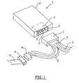
- Figure 1 shows a first embodiment of the invention.
- the reference numeral 1 denotes a signal processing unit, which may be, for example, an antenna amplifier. This may also be radio or television tuner, especially in a particularly advantageous foot point receiver act.
- the invention thus relates to all signal processing electronic units that are present for signal processing and communication within the vehicle.
- the term "signal-processing unit" is not intended to mean units which do not serve to communicate within the vehicle with the driver or occupants of the vehicle.
- the antenna amplifier 1 has a housing 2, wherein within this Housing 2 a printed circuit board, not shown, (or optionally several PCB) is arranged with electrical and electronic components that the Implement the function of the antenna amplifier 1. These components are the high-frequency signals received via antenna conductor structures in the vehicle fed, processed in the antenna amplifier 1 and from this to another Downstream electronic units delivered. It is also the reverse Way conceivable that the vehicle side of the signal processing unit signals supplied, processed there and sent out via the antenna conductor structures become. There is also a power supply for the active amplifier trained antenna amplifier 1 required.
- the housing 2 has an opening 3, in a single slot 4 with a required number of contacts. 5 is arranged. About this slot 4 and the existing contacts there 5 the signal supply or signal output was made to or from the antenna amplifier 1 and its power supply.
- the contacts 5 are electrically connected to the printed circuit board in the housing 2 contacted while the slot 4, in particular the housing, with the circuit board and / or the housing 2 of the antenna amplifier 1 is mechanically connected to produce the required stability.
- the only slot 4 of the antenna amplifier 1 is for recording at least a corresponding connector 6 is formed.
- a corresponding connector 6 is formed on the single connector 6 shown here.
- electrical leads 7 and 8 arranged in an end region 9 in the Connector 6 are merged.
- the electrical lines 7, 8 are of the same design (for example, ribbon cables) or different Type (such as ribbon cables, flexible cables, single stranded or like).
- the antenna amplifier 1 via the electrical line 7 connected to the antenna conductor structure of the vehicle, wherein the antenna conductor structure is not just a conductor pattern in must be a flat component (for example vehicle window) of the vehicle, but also other structures of antennas, advantageously with a Single-wire cable can be connected to the signal-processing unit, are conceivable.
- the line 8 which has a plug 10 at the end, can the antenna amplifier 1 on the vehicle side with the other existing there connected to electronic units. This takes place in FIG. 1 shown embodiment in that the plug 10 with a socket 11th is contacted, wherein on the socket 11, a further electrical line 12th is connected, then within the vehicle to the likewise within the vehicle arranged electronic unit leads. This shows the big advantage of the single slot 4.
- Figure 2 shows another embodiment of the invention, wherein the housing 2 of the antenna amplifier 1 again has an opening 3, in which the only Slot 4 is arranged.
- the Electrical lines 7, 8 each have their own connector 13, 14 are arranged.
- These at least two (or more) connectors 13, 14 are the same or differently designed. It can be plugs or sockets, the corresponding Have contacts.
- the number of contacts depends on the number the electrical conductor of the lines 7, 8, which is the same or different.
- the embodiment of Figure 2 is z. B. shown that the line. 7 Has less electrical conductors, as the line 8. Accordingly, the Connector 13 fewer contacts (not shown) than the connector 14th (also not shown).
- the connectors 13, 14 are both here as Jacks designed so that the slot 4 as a plug with appropriate Number of contacts is formed.
- the slot 4 has more than one plug-in chamber.
- These Plug-in chambers are designated by the reference numerals 15, 16.
- the plug-in chamber 15 takes the connector 14 and the plug-in chamber 16 takes the connector 13 on.
- the inner contours of the plug-in chambers 15, 16 are the Outward contours of the connector 13, 14 adapted. If it is correct Assignment between connector on the one hand and plug-in chamber in the Slot 4 on the other hand, is provided in a further development of the invention, that the plug-in chambers 15, 16 are formed differently. These Coding is realized in FIG.
- the housing has an Opening through which a single or preferably multi-core cable (for Example stranded cable, ribbon cable or the like) is led out that arranged on the one side on the circuit board of the signal processing unit and is electrically contacted.
- this cable is with the single slot and also contacted electrically.
- This Slot can also be made in a separately manufacturable and mountable Housing be arranged.
- the Housing the signal processing unit for example, flat and rectangular is formed (other forms are also conceivable), wherein one surface of the Housing (for example, the bottom or the lid) of the circuit board (and optionally further elements) is formed. This is over at one side the case over and carries the single slot, so even with this Variant the housing an opening (large area and not like the other Variants, a section in a housing wall), in which the only one Slot is arranged. The contact partners of the single slot are then arranged on the guided out of the housing to the outside circuit board and connected to the tracks of the circuit board.
- Other variants, in particular combinations of the variants described above are also readily feasible for the purpose of solving the problem and corresponding advantage achievement.
- FIG. 3 shows a signal processing unit which is the antenna amplifier 1 with its housing 2 acts.
- the antenna amplifier 1 with its housing 2 acts.
- a separate slot for each connector 17 present According to the prior art is a separate slot for each connector 17 present, whereby the disadvantages described above are given.
Landscapes
- Coupling Device And Connection With Printed Circuit (AREA)
Abstract
Description
- Figur 1:
- ein erstes Ausführungsbeispiel der Erfindung,
- Figur 2:
- ein zweites Ausführungsbeispiel der Erfindung,
- Figur 3:
- eine signalverarbeitende Einheit gemäß dem Stand der Technik.
Allgemein bezieht sich die Erfindung somit auf alle signalverarbeitenden elektronischen Einheiten, die zur Signalverarbeitung und Kommunikation innerhalb des Fahrzeuges vorhanden sind. Unter dem Begriff "signalverarbeitende Einheit" sollen solche Einheiten nicht fallen, die sich nicht auf die Kommunikation innerhalb des Fahrzeuges mit Fahrer oder Insassen des Fahrzeuges dienen.
- 1.
- Antennenverstärker
- 2.
- Gehäuse
- 3.
- Öffnung
- 4.
- Steckplatz
- 5.
- Kontakte
- 6.
- Steckverbinder
- 7.
- elektrische Leitung
- 8.
- elektrische Leitung
- 9.
- Endbereich
- 10.
- Stecker
- 11.
- Buchse
- 12.
- elektrische Leitung
- 13.
- Steckverbinder
- 14.
- Steckverbinder
- 15.
- Steckkammer
- 16.
- Steckkammer
- 17.
- Steckplatz
Claims (6)
- Signalverarbeitende Einheit, insbesondere ein Antennenverstärker (1), für ein Fahrzeug, mit einem Gehäuse (2), in dem eine Leiterplatte mit elektronischen Bauteilen zur Realisierung der Funktion der signalverarbeitenden Einheit angeordnet ist, und mit elektrischen Leitungen (7, 8), die mit der signalverarbeitenden Einheit kontaktierbar sind, dadurch gekennzeichnet, dass das Gehäuse (2) eine Öffnung (3) aufweist, in der ein einziger Steckplatz (4) angeordnet ist oder aus der eine Zuleitung zu dem einzigen Steckplatz (4) herausgeführt ist, wobei die elektrischen Leitungen über zumindest einen korrespondierenden Steckverbinder (6, 13, 14) mit dem Steckplatz (4) verbindbar sind.
- Signalverarbeitende Einheit nach Anspruch 1, dadurch gekennzeichnet, dass zumindest eine der Leitungen (7) die signalverarbeitende Einheit mit einer Antennenleiterstruktur des Fahrzeuges verbindet.
- Signalverarbeitende Einheit nach Anspruch 1, dadurch gekennzeichnet, dass zumindest eine der Leitungen (8) die signalverarbeitende Einheit mit einer fahrzeugseitigen Leitung (12) verbindet.
- Signalverarbeitende Einheit nach Anspruch 1, dadurch gekennzeichnet, dass der Steckplatz (4) mehr als eine Steckkammer (15, 16) aufweist.
- Signalverarbeitende Einheit nach Anspruch 4, dadurch gekennzeichnet, dass die Steckkammern (15, 16) unterschiedlich ausgebildet, insbesondere kodiert, sind.
- Signalverarbeitende Einheit nach Anspruch 4, dadurch gekennzeichnet, dass die Steckkammern (15, 16) eine gleiche oder unterschiedliche Anzahl von Kontakten (5) aufweisen.
Applications Claiming Priority (4)
| Application Number | Priority Date | Filing Date | Title |
|---|---|---|---|
| DE102004020200 | 2004-04-22 | ||
| DE102004020200 | 2004-04-22 | ||
| DE102005017397 | 2005-04-14 | ||
| DE102005017397A DE102005017397A1 (de) | 2004-04-22 | 2005-04-14 | Antennenverstärker mit den Steckverbindungen zwischen Antennenverstärker und elektrischen Leitungen |
Publications (1)
| Publication Number | Publication Date |
|---|---|
| EP1589613A1 true EP1589613A1 (de) | 2005-10-26 |
Family
ID=34935512
Family Applications (1)
| Application Number | Title | Priority Date | Filing Date |
|---|---|---|---|
| EP05008730A Withdrawn EP1589613A1 (de) | 2004-04-22 | 2005-04-21 | Antennenverstärker mit den Steckverbindungen zwischen Antennenverstärker und elektrischen Leitungen |
Country Status (2)
| Country | Link |
|---|---|
| EP (1) | EP1589613A1 (de) |
| DE (1) | DE102005017397A1 (de) |
Families Citing this family (1)
| Publication number | Priority date | Publication date | Assignee | Title |
|---|---|---|---|---|
| DE202013005319U1 (de) | 2013-06-11 | 2013-08-19 | Antennentechnik Bad Blankenburg Gmbh | System mit aktiver oder passiver elektronischer signalverarbeitender Einheit, insbesondere Antennenverstärker |
Citations (3)
| Publication number | Priority date | Publication date | Assignee | Title |
|---|---|---|---|---|
| US3355702A (en) * | 1966-06-09 | 1967-11-28 | Gen Electric | Terminal mounting device |
| US6215457B1 (en) * | 1998-09-16 | 2001-04-10 | Siemens Aktiengesellschaft | Transmitter and / or receiver unit for an antitheft system of a motor vehicle |
| EP1156556A2 (de) * | 2000-05-19 | 2001-11-21 | Delphi Technologies, Inc. | Verbindungsmodul |
-
2005
- 2005-04-14 DE DE102005017397A patent/DE102005017397A1/de not_active Withdrawn
- 2005-04-21 EP EP05008730A patent/EP1589613A1/de not_active Withdrawn
Patent Citations (3)
| Publication number | Priority date | Publication date | Assignee | Title |
|---|---|---|---|---|
| US3355702A (en) * | 1966-06-09 | 1967-11-28 | Gen Electric | Terminal mounting device |
| US6215457B1 (en) * | 1998-09-16 | 2001-04-10 | Siemens Aktiengesellschaft | Transmitter and / or receiver unit for an antitheft system of a motor vehicle |
| EP1156556A2 (de) * | 2000-05-19 | 2001-11-21 | Delphi Technologies, Inc. | Verbindungsmodul |
Also Published As
| Publication number | Publication date |
|---|---|
| DE102005017397A1 (de) | 2005-12-15 |
Similar Documents
| Publication | Publication Date | Title |
|---|---|---|
| DE102017219214B4 (de) | Verzweigungsaufbau und kabelbaum | |
| DE3630816A1 (de) | Funktionsschaltung mit einer eingebauten typenverdrahtungsvorrichtung fuer kraftfahrzeuge | |
| EP4068530B1 (de) | Platinenstecker | |
| EP1646106B1 (de) | Steckanordnung für HF-Signalweg | |
| EP1154521B1 (de) | Steckverbinder und Verfahren zur Montage eines Steckverbinders | |
| WO2015107188A2 (de) | Elektronikbaugruppe | |
| EP3944430A1 (de) | Kontaktvorrichtung | |
| DE19724254A1 (de) | Zentralelektrik mit einer Elektrik- oder Elektronikeinheit, insbesondere für Kraftfahrzeuge | |
| DE3781302T2 (de) | Selektiver mehrfachsteckverbindungsblock. | |
| EP3930112A1 (de) | Elektrischer steckverbinder und verfahren zur montage eines elektrischen steckverbinders | |
| DE102004032006B3 (de) | Kontaktelement | |
| DE69411294T2 (de) | Anschlussblock für elektrisches Geräte und Leistungsumformer mit einem derartigen Anschlu block | |
| EP3066723A1 (de) | Prüfkabel sowie buchsenadapter für ein prüfkabel | |
| DE2340773A1 (de) | Uebergabesteckverbindung | |
| DE102005017397A1 (de) | Antennenverstärker mit den Steckverbindungen zwischen Antennenverstärker und elektrischen Leitungen | |
| DE102014118175A1 (de) | Kamera für ein Kraftfahrzeug mit einer Verbindungsvorrichtung, die als oberflächenmontiertes Bauelement ausgebildet ist, sowie Kraftfahrzeug | |
| DE60016105T2 (de) | Elektrisches Anschlussgehäuse | |
| EP1483768B1 (de) | Fernsteuerbares gerät, insbesondere fernsteuerbare zentralverriegelung für kraftfahrzeuge | |
| DE202021106965U1 (de) | Steckverbinder für eine kombinierte elektrische Verbindung und Datenverbindung | |
| DE102021104729A1 (de) | Abschirmblech als Kontaktfeder in einem Steckverbinder | |
| DE102006009582B4 (de) | Elektronisches Gerät eines Fahrzeuges, insbesondere ein Antennenverstärker oder ein TV-Tuner, mit einem Aufnahmeraum für einen Steckverbinder | |
| DE10113905A1 (de) | Koaxialverbindungseinrichtung einer Hochfrequenzleitung sowie Mobiltelefoneinrichtung mit mehradrigen elektrischen Verbindungseinrichtungen | |
| EP3448135A1 (de) | Stecker, steckerbuchse und entsprechendes verbindungssystem | |
| DE102023208907A1 (de) | Steckerelement eines Schirmkabels | |
| DE20121748U1 (de) | Koaxialverbindungseinrichtung einer Hochfrequenzleitung sowie Mobiltelefoneinrichtung mit mehradrigen elektrischen Verbindungseinrichtungen |
Legal Events
| Date | Code | Title | Description |
|---|---|---|---|
| PUAI | Public reference made under article 153(3) epc to a published international application that has entered the european phase |
Free format text: ORIGINAL CODE: 0009012 |
|
| AK | Designated contracting states |
Kind code of ref document: A1 Designated state(s): AT BE BG CH CY CZ DE DK EE ES FI FR GB GR HU IE IS IT LI LT LU MC NL PL PT RO SE SI SK TR |
|
| AX | Request for extension of the european patent |
Extension state: AL BA HR LV MK YU |
|
| 17P | Request for examination filed |
Effective date: 20050902 |
|
| AKX | Designation fees paid |
Designated state(s): AT BE BG CH CY CZ DE DK EE ES FI FR GB GR HU IE IS IT LI LT LU MC NL PL PT RO SE SI SK TR |
|
| 17Q | First examination report despatched |
Effective date: 20051124 |
|
| 17Q | First examination report despatched |
Effective date: 20051124 |
|
| STAA | Information on the status of an ep patent application or granted ep patent |
Free format text: STATUS: THE APPLICATION IS DEEMED TO BE WITHDRAWN |
|
| 18D | Application deemed to be withdrawn |
Effective date: 20070918 |