EP1589613A1 - Antenna amplifier with plug connections between the antenna amplifier and electrical conductors - Google Patents
Antenna amplifier with plug connections between the antenna amplifier and electrical conductors Download PDFInfo
- Publication number
- EP1589613A1 EP1589613A1 EP05008730A EP05008730A EP1589613A1 EP 1589613 A1 EP1589613 A1 EP 1589613A1 EP 05008730 A EP05008730 A EP 05008730A EP 05008730 A EP05008730 A EP 05008730A EP 1589613 A1 EP1589613 A1 EP 1589613A1
- Authority
- EP
- European Patent Office
- Prior art keywords
- signal processing
- processing unit
- slot
- antenna amplifier
- plug
- Prior art date
- Legal status (The legal status is an assumption and is not a legal conclusion. Google has not performed a legal analysis and makes no representation as to the accuracy of the status listed.)
- Withdrawn
Links
- 239000004020 conductor Substances 0.000 title claims abstract description 14
- 238000009434 installation Methods 0.000 description 2
- 238000004891 communication Methods 0.000 description 1
- 238000010276 construction Methods 0.000 description 1
Images


Classifications
-
- H—ELECTRICITY
- H01—ELECTRIC ELEMENTS
- H01R—ELECTRICALLY-CONDUCTIVE CONNECTIONS; STRUCTURAL ASSOCIATIONS OF A PLURALITY OF MUTUALLY-INSULATED ELECTRICAL CONNECTING ELEMENTS; COUPLING DEVICES; CURRENT COLLECTORS
- H01R13/00—Details of coupling devices of the kinds covered by groups H01R12/70 or H01R24/00 - H01R33/00
- H01R13/64—Means for preventing incorrect coupling
-
- H—ELECTRICITY
- H01—ELECTRIC ELEMENTS
- H01R—ELECTRICALLY-CONDUCTIVE CONNECTIONS; STRUCTURAL ASSOCIATIONS OF A PLURALITY OF MUTUALLY-INSULATED ELECTRICAL CONNECTING ELEMENTS; COUPLING DEVICES; CURRENT COLLECTORS
- H01R2201/00—Connectors or connections adapted for particular applications
-
- H—ELECTRICITY
- H01—ELECTRIC ELEMENTS
- H01R—ELECTRICALLY-CONDUCTIVE CONNECTIONS; STRUCTURAL ASSOCIATIONS OF A PLURALITY OF MUTUALLY-INSULATED ELECTRICAL CONNECTING ELEMENTS; COUPLING DEVICES; CURRENT COLLECTORS
- H01R2201/00—Connectors or connections adapted for particular applications
- H01R2201/26—Connectors or connections adapted for particular applications for vehicles
Definitions
- the invention relates to a signal processing unit, in particular a Antenna amplifier, of a vehicle according to the features of the preamble of claim 1.
- antenna amplifiers for Vehicles are used for the production of electrical connections Normally used multipolar connectors, which can be locked, for example are. In this case, such connectors take up much space.
- antenna conductor structures For the Connection to a vehicle-side electrical line and for the connection to the arranged on the vehicle window, for example, antenna conductor structures Several separate connectors are used.
- the Signal processing unit according to the number of existing connectors each separate slots on. This variety of separate slots, which are usually designed differently, leads to a increased space requirement on the circuit board of the antenna amplifier and thus an unnecessary increase in the respective device (see Figure 3).
- the Assembly of such connectors on the part of the signal processing unit is associated with increased effort, resulting in higher installation costs.
- multiple connectors are very expensive, resulting in Increasing the cost of the antenna amplifier leads.
- the invention is therefore based on the object, a signal processing unit to provide, with which the described disadvantages are avoided.
- the housing of the signal processing Unit has an opening in which a single slot is arranged or from which a lead to the single slot (4) is led out, wherein the electrical lines via at least one corresponding connector can be connected to the slot in the signal processing unit.
- the space required in the signal processing unit above all on the board, reduce.
- the assembly time is reduced, and the design of the housing or the printed circuit board simplified, so that in total the system costs (signal processing unit and its components, plug connections and lines) are significantly reduced.
- Even after the later Mounting the signal processing unit in the vehicle is a faster Contacting, i. Connection of the unit to the electrical lines, Given, as a rule, no longer several plugs or sockets with several Slots in the signal processing unit are brought together but these can be plugged into the single slot.
- At least one of the lines connects the signal processing unit with an antenna conductor structure of the vehicle and / or with a vehicle-side line. So is done over the only one Slot and a single line or multiple lines with a single Plug (or socket) or multiple plugs (multiple sockets) the connection the signal processing unit with other electrical or electronic Units that are present on the vehicle.
- This can be about Connections that act to power the signal processing unit concern, as well as the connection of the antenna conductor structure with the as Antenna amplifier trained signal processing unit, and continue the Connection of this unit to downstream units, e.g. signal receivers for radio or television signals.
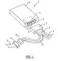
- Figure 1 shows a first embodiment of the invention.
- the reference numeral 1 denotes a signal processing unit, which may be, for example, an antenna amplifier. This may also be radio or television tuner, especially in a particularly advantageous foot point receiver act.
- the invention thus relates to all signal processing electronic units that are present for signal processing and communication within the vehicle.
- the term "signal-processing unit" is not intended to mean units which do not serve to communicate within the vehicle with the driver or occupants of the vehicle.
- the antenna amplifier 1 has a housing 2, wherein within this Housing 2 a printed circuit board, not shown, (or optionally several PCB) is arranged with electrical and electronic components that the Implement the function of the antenna amplifier 1. These components are the high-frequency signals received via antenna conductor structures in the vehicle fed, processed in the antenna amplifier 1 and from this to another Downstream electronic units delivered. It is also the reverse Way conceivable that the vehicle side of the signal processing unit signals supplied, processed there and sent out via the antenna conductor structures become. There is also a power supply for the active amplifier trained antenna amplifier 1 required.
- the housing 2 has an opening 3, in a single slot 4 with a required number of contacts. 5 is arranged. About this slot 4 and the existing contacts there 5 the signal supply or signal output was made to or from the antenna amplifier 1 and its power supply.
- the contacts 5 are electrically connected to the printed circuit board in the housing 2 contacted while the slot 4, in particular the housing, with the circuit board and / or the housing 2 of the antenna amplifier 1 is mechanically connected to produce the required stability.
- the only slot 4 of the antenna amplifier 1 is for recording at least a corresponding connector 6 is formed.
- a corresponding connector 6 is formed on the single connector 6 shown here.
- electrical leads 7 and 8 arranged in an end region 9 in the Connector 6 are merged.
- the electrical lines 7, 8 are of the same design (for example, ribbon cables) or different Type (such as ribbon cables, flexible cables, single stranded or like).
- the antenna amplifier 1 via the electrical line 7 connected to the antenna conductor structure of the vehicle, wherein the antenna conductor structure is not just a conductor pattern in must be a flat component (for example vehicle window) of the vehicle, but also other structures of antennas, advantageously with a Single-wire cable can be connected to the signal-processing unit, are conceivable.
- the line 8 which has a plug 10 at the end, can the antenna amplifier 1 on the vehicle side with the other existing there connected to electronic units. This takes place in FIG. 1 shown embodiment in that the plug 10 with a socket 11th is contacted, wherein on the socket 11, a further electrical line 12th is connected, then within the vehicle to the likewise within the vehicle arranged electronic unit leads. This shows the big advantage of the single slot 4.
- Figure 2 shows another embodiment of the invention, wherein the housing 2 of the antenna amplifier 1 again has an opening 3, in which the only Slot 4 is arranged.
- the Electrical lines 7, 8 each have their own connector 13, 14 are arranged.
- These at least two (or more) connectors 13, 14 are the same or differently designed. It can be plugs or sockets, the corresponding Have contacts.
- the number of contacts depends on the number the electrical conductor of the lines 7, 8, which is the same or different.
- the embodiment of Figure 2 is z. B. shown that the line. 7 Has less electrical conductors, as the line 8. Accordingly, the Connector 13 fewer contacts (not shown) than the connector 14th (also not shown).
- the connectors 13, 14 are both here as Jacks designed so that the slot 4 as a plug with appropriate Number of contacts is formed.
- the slot 4 has more than one plug-in chamber.
- These Plug-in chambers are designated by the reference numerals 15, 16.
- the plug-in chamber 15 takes the connector 14 and the plug-in chamber 16 takes the connector 13 on.
- the inner contours of the plug-in chambers 15, 16 are the Outward contours of the connector 13, 14 adapted. If it is correct Assignment between connector on the one hand and plug-in chamber in the Slot 4 on the other hand, is provided in a further development of the invention, that the plug-in chambers 15, 16 are formed differently. These Coding is realized in FIG.
- the housing has an Opening through which a single or preferably multi-core cable (for Example stranded cable, ribbon cable or the like) is led out that arranged on the one side on the circuit board of the signal processing unit and is electrically contacted.
- this cable is with the single slot and also contacted electrically.
- This Slot can also be made in a separately manufacturable and mountable Housing be arranged.
- the Housing the signal processing unit for example, flat and rectangular is formed (other forms are also conceivable), wherein one surface of the Housing (for example, the bottom or the lid) of the circuit board (and optionally further elements) is formed. This is over at one side the case over and carries the single slot, so even with this Variant the housing an opening (large area and not like the other Variants, a section in a housing wall), in which the only one Slot is arranged. The contact partners of the single slot are then arranged on the guided out of the housing to the outside circuit board and connected to the tracks of the circuit board.
- Other variants, in particular combinations of the variants described above are also readily feasible for the purpose of solving the problem and corresponding advantage achievement.
- FIG. 3 shows a signal processing unit which is the antenna amplifier 1 with its housing 2 acts.
- the antenna amplifier 1 with its housing 2 acts.
- a separate slot for each connector 17 present According to the prior art is a separate slot for each connector 17 present, whereby the disadvantages described above are given.
Landscapes
- Coupling Device And Connection With Printed Circuit (AREA)
Abstract
Description
Die Erfindung betrifft eine signalverarbeitende Einheit, insbesondere einen
Antennenverstärker, eines Fahrzeuges gemäß den Merkmalen des Oberbegriffes
des Patentanspruches 1.The invention relates to a signal processing unit, in particular a
Antenna amplifier, of a vehicle according to the features of the preamble
of
Bei signalverarbeitenden Einheiten, insbesondere Antennenverstärkern, für Fahrzeuge werden für die Herstellung der elektrischen Verbindungen ein- oder im Regelfall mehrpolige Steckverbinder eingesetzt, die zum Beispiel verriegelbar sind. Dabei nehmen solche Steckverbinder viel Platz in Anspruch. Für die Verbindung zu einer fahrzeugseitigen elektrischen Leitung und für die Verbindung zu den auf der Fahrzeugscheibe zum Beispiel angeordneten Antennenleiterstrukturen werden dabei mehrere separate Steckverbinder benutzt. Hierzu weist die signalverarbeitende Einheit entsprechend der Anzahl der vorhandenen Steckverbinder jeweils separate Steckplätze auf. Diese Vielzahl von separaten Steckplätzen, die im Regelfall auch noch unterschiedlich ausgestaltet sind, führt zu einem erhöhten Platzbedarf auf der Leiterplatte des Antennenverstärkers und damit zu einer unnötigen Vergrößerung des jeweiligen Gerätes (siehe Figur 3). Auch die Bestückung solcher Steckverbinder auf Seiten der signalverarbeitenden Einheit ist mit erhöhtem Aufwand verbunden, so dass sich höhere Montagekosten ergeben. Schließlich sind solche mehrere Steckverbinder sehr kostenintensiv, was zur Verteuerung des Antennenverstärkers führt.For signal processing units, in particular antenna amplifiers, for Vehicles are used for the production of electrical connections Normally used multipolar connectors, which can be locked, for example are. In this case, such connectors take up much space. For the Connection to a vehicle-side electrical line and for the connection to the arranged on the vehicle window, for example, antenna conductor structures Several separate connectors are used. For this purpose, the Signal processing unit according to the number of existing connectors each separate slots on. This variety of separate slots, which are usually designed differently, leads to a increased space requirement on the circuit board of the antenna amplifier and thus an unnecessary increase in the respective device (see Figure 3). Also the Assembly of such connectors on the part of the signal processing unit is associated with increased effort, resulting in higher installation costs. Finally, such multiple connectors are very expensive, resulting in Increasing the cost of the antenna amplifier leads.
Der Erfindung liegt daher die Aufgabe zu Grunde, eine signalverarbeitende Einheit bereitzustellen, mit der die geschilderten Nachteile vermieden werden.The invention is therefore based on the object, a signal processing unit to provide, with which the described disadvantages are avoided.
Diese Aufgabe ist durch die Merkmale des Patentanspruches 1 gelöst. This object is solved by the features of
Erfindungsgemäß ist vorgesehen, dass das Gehäuse der signalverarbeitenden Einheit eine Öffnung aufweist, in der ein einziger Steckplatz angeordnet ist oder aus der eine Zuleitung zu dem einzigen Steckplatz (4) herausgeführt ist, wobei die elektrischen Leitungen über zumindest einen korrespondierenden Steckverbinder mit dem Steckplatz in der signalverarbeitenden Einheit verbindbar sind. Dadurch lässt sich der Platzbedarf bei der signalverarbeitenden Einheit, vor allen Dingen auf deren Leiterplatte, reduzieren. Weiterhin wird die Montagezeit verringert, und die Gestaltung des Gehäuses bzw. der Leiterplatte vereinfacht, so dass insgesamt die Systemkosten (signalverarbeitende Einheit und deren Bauteile, Steckverbindungen und Leitungen) deutlich reduziert werden. Auch nach der späteren Montage der signalverarbeitenden Einheit in dem Fahrzeug ist eine schnellere Kontaktierung, d.h. Verbindung der Einheit mit den elektrischen Leitungen, gegeben, da im Regelfall nicht mehr mehrere Stecker oder Buchsen mit mehreren Steckplätzen in der signalverarbeitenden Einheit zusammengebracht werden müssen, sondern diese in den einzigen Steckplatz eingesteckt werden können.According to the invention it is provided that the housing of the signal processing Unit has an opening in which a single slot is arranged or from which a lead to the single slot (4) is led out, wherein the electrical lines via at least one corresponding connector can be connected to the slot in the signal processing unit. Thereby can the space required in the signal processing unit, above all on the board, reduce. Furthermore, the assembly time is reduced, and the design of the housing or the printed circuit board simplified, so that in total the system costs (signal processing unit and its components, plug connections and lines) are significantly reduced. Even after the later Mounting the signal processing unit in the vehicle is a faster Contacting, i. Connection of the unit to the electrical lines, Given, as a rule, no longer several plugs or sockets with several Slots in the signal processing unit are brought together but these can be plugged into the single slot.
In Weiterbildung der Erfindung verbindet zumindest eine der Leitungen die signalverarbeitende Einheit mit einer Antennenleiterstruktur des Fahrzeuges und/oder mit einer fahrzeugseitigen Leitung. So erfolgt über den einzigen Steckplatz und eine einzige Leitung oder mehrere Leitungen mit einem einzigen Stecker (oder Buchse) oder mehreren Steckern (mehrere Buchsen) die Verbindung der signalverarbeitenden Einheit mit weiteren elektrischen oder elektronischen Einheiten, die fahrzeugseitig vorhanden sind. Hierbei kann es sich um Verbindungen handeln, die die Stromversorgung der signalverarbeitenden Einheit betreffen, genauso gut wie die Verbindung der Antennenleiterstruktur mit der als Antennenverstärker ausgebildeten signalverarbeitenden Einheit, und weiterhin die Verbindung dieser Einheit mit nachgeschalteten Einheiten, wie z.B. Signalempfängern für Rundfunk- oder Fernsehsignale.In a further development of the invention, at least one of the lines connects the signal processing unit with an antenna conductor structure of the vehicle and / or with a vehicle-side line. So is done over the only one Slot and a single line or multiple lines with a single Plug (or socket) or multiple plugs (multiple sockets) the connection the signal processing unit with other electrical or electronic Units that are present on the vehicle. This can be about Connections that act to power the signal processing unit concern, as well as the connection of the antenna conductor structure with the as Antenna amplifier trained signal processing unit, and continue the Connection of this unit to downstream units, e.g. signal receivers for radio or television signals.
Weitere Ausgestaltungen der Erfindung sind in den Unteransprüchen angegeben, aus denen entsprechende Vorteile resultieren. Außerdem sind Ausführungsbeispiele der Erfindung im Folgenden beschrieben und anhand der Figuren erläutert, wobei die Erfindung nicht auf diese Ausführungsbeispiele beschränkt ist und in üblicher Weise den jeweiligen Einsatzbedingungen anpassbar ist.Further embodiments of the invention are specified in the subclaims, which results in corresponding benefits. In addition, embodiments are of the invention described below and explained with reference to the figures, the invention is not limited to these embodiments and in usually customizable to the particular conditions of use.
Es zeigen:
- Figur 1:
- ein erstes Ausführungsbeispiel der Erfindung,
- Figur 2:
- ein zweites Ausführungsbeispiel der Erfindung,
- Figur 3:
- eine signalverarbeitende Einheit gemäß dem Stand der Technik.
- FIG. 1:
- a first embodiment of the invention,
- FIG. 2:
- A second embodiment of the invention,
- FIG. 3:
- a signal processing unit according to the prior art.
Figur 1 zeigt ein erstes Ausführungsbeispiel der Erfindung. Mit der Bezugsziffer 1
ist, soweit im Einzelnen dargestellt, eine signalverarbeitende Einheit bezeichnet,
bei der es sich beispielsweise um einen Antennenverstärker handeln kann.
Hierbei kann es sich auch um Rundfunk- bzw. Fernseh-Tuner, insbesondere in
besonders vorteilhafter Weise Fußpunktempfänger, handeln.
Allgemein bezieht sich die Erfindung somit auf alle signalverarbeitenden elektronischen
Einheiten, die zur Signalverarbeitung und Kommunikation innerhalb des
Fahrzeuges vorhanden sind. Unter dem Begriff "signalverarbeitende Einheit"
sollen solche Einheiten nicht fallen, die sich nicht auf die Kommunikation
innerhalb des Fahrzeuges mit Fahrer oder Insassen des Fahrzeuges dienen.Figure 1 shows a first embodiment of the invention. The
In general, the invention thus relates to all signal processing electronic units that are present for signal processing and communication within the vehicle. The term "signal-processing unit" is not intended to mean units which do not serve to communicate within the vehicle with the driver or occupants of the vehicle.
Der Antennenverstärker 1 weist ein Gehäuse 2 auf, wobei innerhalb dieses
Gehäuses 2 eine nicht dargestellte Leiterplatte (oder gegebenenfalls mehrere
Leiterplatten) mit elektrischen und elektronischen Bauteilen angeordnet ist, die die
Funktion des Antennenverstärkers 1 realisieren. Diesen Bauteilen werden die
über Antennenleiterstrukturen im Fahrzeug empfangenen hochfrequenten Signale
zugeführt, im Antennenverstärker 1 verarbeitet und von diesem an weitere
nachgeschaltete elektronische Einheiten abgegeben. Dabei ist auch der umgekehrte
Weg denkbar, dass fahrzeugseitig der signalverarbeitenden Einheit Signale
zugeführt, dort verarbeitet und über die Antennenleiterstrukturen ausgesendet
werden. Außerdem ist eine Stromversorgung für den als aktiven Verstärker
ausgebildeten Antennenverstärker 1 erforderlich. The
Erfindungsgemäß ist vorgesehen, dass das Gehäuse 2 eine Öffnung 3 aufweist,
in der ein einziger Steckplatz 4 mit einer erforderlichen Anzahl von Kontakten 5
angeordnet ist. Über diesen Steckplatz 4 bzw. die dort vorhandenen Kontakte 5
erfolgte die Signalzufuhr bzw. Signalabgabe an bzw. von dem Antennenverstärker
1 sowie dessen Stromversorgung. Die Kontakte 5 sind elektrisch mit der Leiterplatte
in dem Gehäuse 2 kontaktiert, während der Steckplatz 4, insbesondere
dessen Gehäuse, mit der Leiterplatte und/oder dem Gehäuse 2 des Antennenverstärkers
1 mechanisch verbunden ist, um die erforderliche Stabilität zu erzeugen.According to the invention, it is provided that the
Der einzige Steckplatz 4 des Antennenverstärkers 1 ist zur Aufnahme zumindest
eines korrespondierenden Steckverbinders 6 ausgebildet. So ist beispielsweise
der Steckplatz 4 in Steckerform und der Steckverbinder 6 in Buchsenform (oder
umgekehrt) ausgebildet. An dem hier dargestellten einzigen Steckverbinder 6 sind
elektrische Leitungen 7 und 8 angeordnet, die in einem Endbereich 9 in dem
Steckverbinder 6 zusammengeführt werden. Die elektrischen Leitungen 7, 8 sind
von gleicher Bauform (beispielsweise Flachbandleitungen) oder unterschiedlicher
Bauform (so z.B. Flachbandleitungen, flexible Leitungen, Einzellitzen oder
dergleichen). Bei dieser Ausgestaltung wird der Antennenverstärker 1 über die
elektrische Leitung 7 mit der Antennenleiterstruktur des Fahrzeuges verbunden,
wobei es sich bei der Antennenleiterstruktur nicht nur um eine Leiterstruktur in
einem flächigen Bauteil (z.B. Fahrzeugscheibe) des Fahrzeuges handeln muss,
sondern auch andere Strukturen von Antennen, die in vorteilhafter Weise mit einer
Eindrahtleitung an die signalverarbeitende Einheit angeschlossen werden,
denkbar sind. Über die Leitung 8, die endseitig einen Stecker 10 aufweist, kann
der Antennenverstärker 1 fahrzeugseitig mit den dort vorhandenen weiteren
elektronischen Einheiten verbunden werden. Dies erfolgt beim in Figur 1
gezeigten Ausführungsbeispiel dadurch, dass der Stecker 10 mit einer Buchse 11
kontaktiert wird, wobei an der Buchse 11 eine weitere elektrische Leitung 12
angeschlossen ist, die dann innerhalb des Fahrzeuges zu der ebenfalls innerhalb
des Fahrzeuges angeordneten elektronischen Einheit führt. Hierbei zeigt sich der
große Vorteil des einzigen Steckplatzes 4. Dieser ist darin zu sehen, dass die
elektrischen Leitungen 7, 8 (und gegebenenfalls 12) schon fahrzeugseitig verlegt
werden können. Wenn dann der Antennenverstärker 1 an seinem vorgesehenen
Ort eingebaut wird, ist es nur noch erforderlich, den zumindest einen Steckverbinder
6 in den einzigen Steckplatz 4 des Antennenverstärkers einzustecken.
Dadurch ist gerade für den Fahrzeughersteller ein großer Montagevorteil
gegeben.The
Figur 2 zeigt ein weiteres Ausführungsbeispiel der Erfindung, wobei das Gehäuse
2 des Antennenverstärkers 1 wieder eine Öffnung 3 aufweist, in der der einzige
Steckplatz 4 angeordnet ist. Bei dieser Ausgestaltung ist an den Enden der
elektrischen Leitungen 7, 8 jeweils ein eigener Steckverbinder 13, 14 angeordnet.
Diese zumindest zwei (oder mehr) Steckverbinder 13, 14 sind gleich oder
unterschiedlich ausgestaltet. Es können Stecker oder Buchsen sein, die entsprechende
Kontakte aufweisen. Die Anzahl der Kontakte richtet sich nach der Anzahl
der elektrischen Leiter der Leitungen 7, 8, die gleich oder unterschiedlich ist. In
dem Ausführungsbeispiel gemäß Figur 2 ist z. B. dargestellt, dass die Leitung 7
weniger elektrische Leiter aufweist, als die Leitung 8. Dementsprechend hat der
Steckverbinder 13 weniger Kontakte (nicht dargestellt) als der Steckverbinder 14
(ebenfalls nicht dargestellt). Die Steckverbinder 13, 14 sind hier beide als
Buchsen ausgestaltet, so dass der Steckplatz 4 als Stecker mit entsprechender
Anzahl von Kontakten ausgebildet ist. Hier ist in Weiterbildung der Erfindung
erkennbar, dass der Steckplatz 4 mehr als eine Steckkammer aufweist. Diese
Steckkammern sind mit den Bezugsziffern 15, 16 bezeichnet. Die Steckkammer
15 nimmt den Steckverbinder 14 und die Steckkammer 16 nimmt den Steckverbinder
13 auf. Hierzu sind die Innenkonturen der Steckkammern 15, 16 den
Außenkonturen der Steckverbinder 13, 14 angepasst. Wenn es auf die korrekte
Zuordnung zwischen Steckverbinder einerseits und Steckkammer in dem
Steckplatz 4 andererseits ankommt, ist in Weiterbildung der Erfindung vorgesehen,
dass die Steckkammern 15, 16 unterschiedlich ausgebildet sind. Diese
Kodierung ist in Figur 2 beispielsweise dadurch realisiert, dass die Längserstreckung
der Steckkammer 16 kleiner ist als die der Steckkammer 15 und somit der
Längserstreckung des einzusetzenden Steckverbinders 13, 14 entspricht. Für eine
Verpolungssicherheit ist diese Kodierung derart gestaltet, dass z.B. der Steckverbinder
13 nur in einer einzigen Position in die Steckkammer 16 eingesetzt werden
kann. Alternativ oder ergänzend können zwecks Kodierung Stege, Rippen oder
dergleichen vorgesehen werden. Neben dieser konstruktiven Kodierung der
Steckkammern und deren korrespondierenden Steckverbinder kann auch an eine
farbliche Kodierung gedacht werden. Auf Grund der unterschiedlichen Längserstreckungen
der Steckverbinder 13, 14 und deren zugehörigen Steckkammern
15, 16 des Steckplatzes 4 ist auch eine unterschiedliche Anzahl von Kontakten
innerhalb der Steckkammern 15, 16 vorhanden. Dies kann so sein, muss aber
nicht. So kann in den Steckkammern 15, 16 auch die gleiche Anzahl von
Kontakten angeordnet sein. Während bisher der einzige Steckplatz 4 so ausgebildet
und beschrieben war, dass er nur den einen Steckverbinder 6 oder die zwei
Steckverbinder 13, 14 aufnimmt, kann der Steckplatz 4 auch dazu ausgebildet
sein, mehr als zwei Steckverbinder aufzunehmen. Diese müssen auch nicht, wie
in Figur 2 gezeigt, nebeneinander angeordnet sein, sondern können alternativ
oder ergänzend auch übereinander angeordnet werden. Die in Figur 2 gezeigte
Ausführungsform von Steckplatz 4 und korrespondierenden Steckverbindern 13,
14 hat den Vorteil einer besonders flach bauenden Konstruktion.Figure 2 shows another embodiment of the invention, wherein the
Die weitere Alternative, dass nämlich das Gehäuse eine Öffnung aufweist, aus der eine Zuleitung zu dem einzigen Steckplatz (4) herausgeführt ist, ist in verschiedenen Varianten ausführbar. Bei einer ersten Variante weist das Gehäuse eine Öffnung auf, durch die ein ein- oder vorzugsweise mehradriges Kabel (zum Beispiel Litzenkabel, Flachbandkabel oder dergleichen) herausgeführt ist, dass auf der einen Seite an der Leiterplatte der signalverarbeitenden Einheit angeordnet und elektrisch kontaktiert ist. Auf der anderen Seite ist dieses Kabel mit dem einzigen Steckplatz versehen und ebenfalls elektrisch kontaktiert. Dieser Steckplatz kann ebenfalls in einem separat herstellbaren und montierbaren Gehäuse angeordnet sein. Eine weitere Variante ist darin zu sehen, dass das Gehäuse der signalverarbeitenden Einheit beispielsweise flach und rechteckig ausgebildet ist (andere Formen sind auch denkbar), wobei eine Fläche des Gehäuses (zum Beispiel der Boden oder der Deckel) von der Leiterplatte (und gegebenenfalls weiterer Elemente) gebildet ist. Diese steht an einer Seite über das Gehäuse über und trägt den einzigen Steckplatz, so dass auch bei dieser Variante das Gehäuse eine Öffnung (großflächig und nicht, wie den anderen Varianten, ein Ausschnitt in einer Gehäusewand) aufweist, in der der einzige Steckplatz angeordnet ist. Die Kontaktpartner des einzigen Steckplatzes sind dann auf der aus dem Gehäuse nach außen geführten Leiterplatte angeordnet und mit den Leiterbahnen der Leiterplatte verbunden. Weitere Varianten, insbesondere Kombinationen der vorstehend beschriebenen Varianten, sind ebenfalls ohne weiteres realisierbar zwecks Lösung der gestellten Aufgabe und entsprechender Vorteilserzielung.The further alternative, namely that the housing has an opening, from the a lead is led out to the single slot (4) is in different Variants executable. In a first variant, the housing has a Opening through which a single or preferably multi-core cable (for Example stranded cable, ribbon cable or the like) is led out that arranged on the one side on the circuit board of the signal processing unit and is electrically contacted. On the other hand, this cable is with the single slot and also contacted electrically. This Slot can also be made in a separately manufacturable and mountable Housing be arranged. Another variant is the fact that the Housing the signal processing unit, for example, flat and rectangular is formed (other forms are also conceivable), wherein one surface of the Housing (for example, the bottom or the lid) of the circuit board (and optionally further elements) is formed. This is over at one side the case over and carries the single slot, so even with this Variant the housing an opening (large area and not like the other Variants, a section in a housing wall), in which the only one Slot is arranged. The contact partners of the single slot are then arranged on the guided out of the housing to the outside circuit board and connected to the tracks of the circuit board. Other variants, in particular combinations of the variants described above are also readily feasible for the purpose of solving the problem and corresponding advantage achievement.
Figur 3 zeigt eine signalverarbeitende Einheit, bei der es sich um den Antennenverstärker
1 mit seinem Gehäuse 2 handelt. Bei diesem Ausführungsbeispiel
gemäß dem Stand der Technik ist für jeden Steckverbinder ein eigener Steckplatz
17 vorhanden, wodurch die eingangs beschriebenen Nachteile gegeben sind. Figure 3 shows a signal processing unit which is the
- 1.1.
- Antennenverstärkerantenna amplifier
- 2.Second
- Gehäusecasing
- 3.Third
- Öffnungopening
- 4.4th
- Steckplatzslot
- 5.5th
- Kontaktecontacts
- 6.6th
- SteckverbinderConnectors
- 7.7th
- elektrische Leitungelectrical line
- 8.8th.
- elektrische Leitungelectrical line
- 9.9th
- Endbereichend
- 10.10th
- Steckerplug
- 11.11th
- BuchseRifle
- 12.12th
- elektrische Leitungelectrical line
- 13.13th
- SteckverbinderConnectors
- 14.14th
- SteckverbinderConnectors
- 15.15th
- Steckkammersocket chamber
- 16.16th
- Steckkammersocket chamber
- 17.17th
- Steckplatzslot
Claims (6)
Applications Claiming Priority (4)
| Application Number | Priority Date | Filing Date | Title |
|---|---|---|---|
| DE102004020200 | 2004-04-22 | ||
| DE102004020200 | 2004-04-22 | ||
| DE102005017397A DE102005017397A1 (en) | 2004-04-22 | 2005-04-14 | Antenna amplifier with the connections between the antenna amplifier and electrical cables |
| DE102005017397 | 2005-04-14 |
Publications (1)
| Publication Number | Publication Date |
|---|---|
| EP1589613A1 true EP1589613A1 (en) | 2005-10-26 |
Family
ID=34935512
Family Applications (1)
| Application Number | Title | Priority Date | Filing Date |
|---|---|---|---|
| EP05008730A Withdrawn EP1589613A1 (en) | 2004-04-22 | 2005-04-21 | Antenna amplifier with plug connections between the antenna amplifier and electrical conductors |
Country Status (2)
| Country | Link |
|---|---|
| EP (1) | EP1589613A1 (en) |
| DE (1) | DE102005017397A1 (en) |
Families Citing this family (1)
| Publication number | Priority date | Publication date | Assignee | Title |
|---|---|---|---|---|
| DE202013005319U1 (en) | 2013-06-11 | 2013-08-19 | Antennentechnik Bad Blankenburg Gmbh | System with active or passive electronic signal processing unit, in particular antenna amplifier |
Citations (3)
| Publication number | Priority date | Publication date | Assignee | Title |
|---|---|---|---|---|
| US3355702A (en) * | 1966-06-09 | 1967-11-28 | Gen Electric | Terminal mounting device |
| US6215457B1 (en) * | 1998-09-16 | 2001-04-10 | Siemens Aktiengesellschaft | Transmitter and / or receiver unit for an antitheft system of a motor vehicle |
| EP1156556A2 (en) * | 2000-05-19 | 2001-11-21 | Delphi Technologies, Inc. | Connector module |
-
2005
- 2005-04-14 DE DE102005017397A patent/DE102005017397A1/en not_active Withdrawn
- 2005-04-21 EP EP05008730A patent/EP1589613A1/en not_active Withdrawn
Patent Citations (3)
| Publication number | Priority date | Publication date | Assignee | Title |
|---|---|---|---|---|
| US3355702A (en) * | 1966-06-09 | 1967-11-28 | Gen Electric | Terminal mounting device |
| US6215457B1 (en) * | 1998-09-16 | 2001-04-10 | Siemens Aktiengesellschaft | Transmitter and / or receiver unit for an antitheft system of a motor vehicle |
| EP1156556A2 (en) * | 2000-05-19 | 2001-11-21 | Delphi Technologies, Inc. | Connector module |
Also Published As
| Publication number | Publication date |
|---|---|
| DE102005017397A1 (en) | 2005-12-15 |
Similar Documents
| Publication | Publication Date | Title |
|---|---|---|
| DE102017219214B4 (en) | BRANCH STRUCTURE AND WIRING HARNESS | |
| DE3630816A1 (en) | FUNCTION CIRCUIT WITH A BUILT-IN TYPE WIRING DEVICE FOR MOTOR VEHICLES | |
| EP1646106B1 (en) | Connector arrangement for RF signal path | |
| WO2015107188A2 (en) | Electronic module | |
| EP3944430A1 (en) | Contact device | |
| DE19724254A1 (en) | Central electrical arrangement esp for motor vehicle | |
| DE3781302T2 (en) | SELECTIVE MULTIPLE CONNECTING BLOCK. | |
| EP3930112A1 (en) | Electric connector and method for mounting of a connector | |
| EP1589613A1 (en) | Antenna amplifier with plug connections between the antenna amplifier and electrical conductors | |
| EP4068530B1 (en) | Circuit board connector | |
| DE102004032006B3 (en) | Contact element for electrically contacting a coaxial cable to a circuit board, comprises electrically conducting inner and outer contact elements and a dielectric | |
| DE69411294T2 (en) | Terminal block for electrical devices and power converters with such a terminal block | |
| WO2016062448A1 (en) | Test cable and jack adapter for a test cable | |
| DE2340773A1 (en) | Transfer plug connector for wiring system with spring strip - has terminal pins protruding above wiring plane for connection to respective cct. boards | |
| DE60016105T2 (en) | Electrical connection housing | |
| EP1483768B1 (en) | Remotely controlled device, particularly remotely controlled central lock for motor vehicles | |
| DE202021106965U1 (en) | Connector for a combined electrical connection and data connection | |
| DE102021104729A1 (en) | Shielding plate as a contact spring in a connector | |
| DE102006009582B4 (en) | Electronic device of a vehicle, in particular an antenna amplifier or a TV tuner, with a receiving space for a connector | |
| EP2987682A1 (en) | Assembly for electrical wires installed in a motor vehicle | |
| DE60207837T2 (en) | DEVICE FOR VEHICLES | |
| DE10113905A1 (en) | Coaxial connection device for use with high-frequency line, has first and second connection elements in continuous electrical contact without interlocking to form coaxial connection | |
| EP3448135A1 (en) | Connector, socket and corresponding connection system | |
| DE102023208907A1 (en) | Connector element of a shielded cable | |
| DE20121748U1 (en) | Coaxial connection device of a high-frequency line and mobile telephone device with multi-core electrical connection devices |
Legal Events
| Date | Code | Title | Description |
|---|---|---|---|
| PUAI | Public reference made under article 153(3) epc to a published international application that has entered the european phase |
Free format text: ORIGINAL CODE: 0009012 |
|
| AK | Designated contracting states |
Kind code of ref document: A1 Designated state(s): AT BE BG CH CY CZ DE DK EE ES FI FR GB GR HU IE IS IT LI LT LU MC NL PL PT RO SE SI SK TR |
|
| AX | Request for extension of the european patent |
Extension state: AL BA HR LV MK YU |
|
| 17P | Request for examination filed |
Effective date: 20050902 |
|
| AKX | Designation fees paid |
Designated state(s): AT BE BG CH CY CZ DE DK EE ES FI FR GB GR HU IE IS IT LI LT LU MC NL PL PT RO SE SI SK TR |
|
| 17Q | First examination report despatched |
Effective date: 20051124 |
|
| 17Q | First examination report despatched |
Effective date: 20051124 |
|
| STAA | Information on the status of an ep patent application or granted ep patent |
Free format text: STATUS: THE APPLICATION IS DEEMED TO BE WITHDRAWN |
|
| 18D | Application deemed to be withdrawn |
Effective date: 20070918 |