EP1589526A2 - Optisches Aufzeichnungsmedium, Vorrichtung und Verfahren zur Aufzeichnung von Daten auf dieses Medium - Google Patents
Optisches Aufzeichnungsmedium, Vorrichtung und Verfahren zur Aufzeichnung von Daten auf dieses Medium Download PDFInfo
- Publication number
- EP1589526A2 EP1589526A2 EP05103245A EP05103245A EP1589526A2 EP 1589526 A2 EP1589526 A2 EP 1589526A2 EP 05103245 A EP05103245 A EP 05103245A EP 05103245 A EP05103245 A EP 05103245A EP 1589526 A2 EP1589526 A2 EP 1589526A2
- Authority
- EP
- European Patent Office
- Prior art keywords
- area
- data
- optical disc
- record
- bordered
- Prior art date
- Legal status (The legal status is an assumption and is not a legal conclusion. Google has not performed a legal analysis and makes no representation as to the accuracy of the status listed.)
- Withdrawn
Links
Images


Classifications
-
- G—PHYSICS
- G11—INFORMATION STORAGE
- G11B—INFORMATION STORAGE BASED ON RELATIVE MOVEMENT BETWEEN RECORD CARRIER AND TRANSDUCER
- G11B7/00—Recording or reproducing by optical means, e.g. recording using a thermal beam of optical radiation by modifying optical properties or the physical structure, reproducing using an optical beam at lower power by sensing optical properties; Record carriers therefor
- G11B7/007—Arrangement of the information on the record carrier, e.g. form of tracks, actual track shape, e.g. wobbled, or cross-section, e.g. v-shaped; Sequential information structures, e.g. sectoring or header formats within a track
- G11B7/00736—Auxiliary data, e.g. lead-in, lead-out, Power Calibration Area [PCA], Burst Cutting Area [BCA], control information
-
- H—ELECTRICITY
- H02—GENERATION; CONVERSION OR DISTRIBUTION OF ELECTRIC POWER
- H02G—INSTALLATION OF ELECTRIC CABLES OR LINES, OR OF COMBINED OPTICAL AND ELECTRIC CABLES OR LINES
- H02G3/00—Installations of electric cables or lines or protective tubing therefor in or on buildings, equivalent structures or vehicles
- H02G3/02—Details
- H02G3/04—Protective tubing or conduits, e.g. cable ladders or cable troughs
- H02G3/0437—Channels
-
- G—PHYSICS
- G11—INFORMATION STORAGE
- G11B—INFORMATION STORAGE BASED ON RELATIVE MOVEMENT BETWEEN RECORD CARRIER AND TRANSDUCER
- G11B27/00—Editing; Indexing; Addressing; Timing or synchronising; Monitoring; Measuring tape travel
- G11B27/10—Indexing; Addressing; Timing or synchronising; Measuring tape travel
- G11B27/19—Indexing; Addressing; Timing or synchronising; Measuring tape travel by using information detectable on the record carrier
-
- H—ELECTRICITY
- H02—GENERATION; CONVERSION OR DISTRIBUTION OF ELECTRIC POWER
- H02G—INSTALLATION OF ELECTRIC CABLES OR LINES, OR OF COMBINED OPTICAL AND ELECTRIC CABLES OR LINES
- H02G3/00—Installations of electric cables or lines or protective tubing therefor in or on buildings, equivalent structures or vehicles
- H02G3/28—Installations of cables, lines, or separate protective tubing therefor in conduits or ducts pre-established in walls, ceilings or floors
- H02G3/283—Installations of cables, lines, or separate protective tubing therefor in conduits or ducts pre-established in walls, ceilings or floors in floors
-
- G—PHYSICS
- G07—CHECKING-DEVICES
- G07B—TICKET-ISSUING APPARATUS; FARE-REGISTERING APPARATUS; FRANKING APPARATUS
- G07B15/00—Arrangements or apparatus for collecting fares, tolls or entrance fees at one or more control points
- G07B15/02—Arrangements or apparatus for collecting fares, tolls or entrance fees at one or more control points taking into account a variable factor such as distance or time, e.g. for passenger transport, parking systems or car rental systems
- G07B15/04—Arrangements or apparatus for collecting fares, tolls or entrance fees at one or more control points taking into account a variable factor such as distance or time, e.g. for passenger transport, parking systems or car rental systems comprising devices to free a barrier, turnstile, or the like
Definitions
- the present invention relates to a technique for recording a user data on an optical disc medium, and more particularly to an optical disc medium, and an optical disc apparatus using the same, and a recording method on the same.
- a ROM (Read Only Memory) medium dedicated to reproduction is first spread widely in which an embossed data pit string is formed in advance, and then CD-R (Compact Disc-Recordable) and DVD-R (Digital Versatile Disc-Recordable) that a user data can be recorded are widely spread.
- CD-RW Compact Disc-Recordable
- DVD-RW Digital Versatile Disc-Recordable
- CD-RW Compact Disc-ReWritable
- DVD-RW DVD-RW
- DVD-RW DVD-RW
- the recording type optical disc medium a spiral groove track is formed on an optical disc substrate, and a multi-layer recording layer made of an organic material and the like is formed thereon. A laser beam of high power is focused on this recording layer to change the property of the recording layer and to form a record pit. Thus, a data is recorded on the optical disc medium.
- the optical disc medium after the recording operation has a same data format as the ROM medium, and a servo signal of the substantially same property as the ROM medium can be obtained form the optical disc medium on which the data recorded.
- the optical disc apparatus dedicated to the reproduction can carry out the reproduction of the recorded user data on the optical disc medium.
- a user data is subjected to a format conversion into a format in which a data ID such as an address, and an error correction code are added, and then is recorded as a series of continuous data on the optical disc medium.
- This continuous record format is the same format as that of the DVD-ROM.
- the optical disc medium is given the perfectly same format as the DVD-ROM, the user data can be recorded only once. Therefore, a recording method called a multi-session and multi-border is adopted to permit the user data to be recorded additionally several times. In this case, a special data called a bordered area where data of a data position and the like is recorded is provided after the user data, and another user data is further recorded thereafter.
- a reproducing apparatus can reproduce the user data by using the data position data.
- JP-A 2000-504462 discloses a writing apparatus which includes a writing unit and a positioning unit.
- the writing unit writes a mark indicating a data block in an area of a recording medium with an electromagnetic emission beam, in order to write the data block on a track pattern of the rewritable recording medium.
- the positioning unit positions the writing unit in accordance with a track structure of the recording medium.
- the track structure has the track pattern.
- Such a writing apparatus has a first detecting unit, a second detecting unit and an initializing unit.
- the first detecting unit detects the area of the recording medium used to write the data block.
- the second detecting unit detects a non-written boundary area adjacent to the used area.
- the initializing unit writes a dummy data to the non-written boundary area.
- JP-A 2000-504463 discloses a writing apparatus, which writes a data block to a track pattern on a writable recording medium.
- This writing apparatus includes a writing unit and a positioning unit.
- the writing unit writes a mark indicating a data block into the area of the recording medium with an electromagnetic emission beam.
- the positioning unit positions the writing unit on the recording medium in accordance with a track structure indicating a track pattern.
- This writing apparatus includes a state unit for generating a state data to indicate the fact that a write operation is carried out on at least one area of the recording medium.
- the state data is extended from a start section of the track pattern area in which the data block is written, and has an initial area data for indicating an initial area to which it is written without any interruption.
- An object of the present invention is to provide an optical disc apparatus in which a processing time of a finalizing process can be reduced when a recording operation is completed, and a recording method in an optical disc medium, and the optical disc medium used in an optical disc apparatus.
- Another object of the present invention is to provide an optical disc medium in which a recordable capacity can be increased so as to be recognized from a user side, an optical disc apparatus using the same, and an optical disc data recording method in the optical disc apparatus.
- an optical disc medium in an aspect of the present invention, includes a system area and a data area following the system area.
- the data area includes at least one bordered area and a border area after the bordered area.
- a record control data in a recording operation of a user data in the bordered area is recorded in the system area.
- the data area may further include a lead-out area provided on an outermost circumference side in the data area.
- the lead-out area may have a record capacity equal to or less than that of the bordered area.
- the bordered area on the outermost circumference side may be a final area where a data is recorded.
- a finalizing data is recorded in the bordered area on the outermost circumference side.
- a data indicating the bordered area on the outermost circumference side is in the system area.
- the system area may include a test record area, a record control data area and a user data lead-in area.
- a trial recording operation is carried out to the test record area to determine an optimal record condition when the user data is recorded in the data area.
- a data is recorded in the user data lead-in area to indicate a start position of the data area.
- the data indicating the bordered area on the outermost circumference side is recorded in the record control data area.
- a data recording method in an optical disc medium is achieved by providing an optical disc medium which includes a system area and a data area following the system area, wherein the data area includes at least one bordered area and a border area after the bordered area, by recording a user data in the bordered area; and by setting a border area after the bordered area when the record of the user data is completed.
- the data recording method may be achieved by further setting a lead-out area on an outermost circumference side in the data area.
- the lead-out area may have a record capacity equal to or less than that of the bordered area.
- the data recording method may be achieved by further setting the bordered area on the outermost circumference side in the data area as a final area where a data is recorded.
- the setting may be achieved by recording a finalizing data in the bordered area on the outermost circumference side.
- the data recording method may be achieved by further recording a data indicating the bordered area on the outermost circumference side in the system area as a record control data.
- the system area may include a test record area, a record control data area and a user data lead-in area.
- a trial recording operation is carried out to the test record area to determine an optimal record condition when the user data is recorded in the data area.
- a data is recorded in the user data lead-in area to indicate a start position of the data area.
- the recording a data may be achieved by recording the data indicating the bordered area on the outermost circumference side in the record control data area.
- an optical disc apparatus in another aspect of the present invention, includes a rotation drive system, an access unit, and a control section.
- the rotation drive system rotates an optical disc medium which includes a system area and a data area following the system area, wherein the data area includes at least one bordered area and a border area after the bordered area.
- the control section controls the rotation drive system to rotate the optical disc medium; and encodes a record data and controls the access unit to irradiate a laser beam such that the encoded data is recorded on the optical disc medium.
- the control section controls the access unit such that a user data is recorded in the bordered area, and the border area is set when the record of the user data is completed.
- control section may control the access unit such that a lead-out area is set on an outermost circumference side in the data area.
- the lead-out area may have a record capacity equal to or less than that of the bordered area.
- control section may control the access unit such that the bordered area on the outermost circumference side in the data area is set as a final area where a data is recorded.
- control section may control the access unit to record a finalizing data in the bordered area on the outermost circumference side.
- control section may control the access unit to record a data indicating the bordered area on the outermost circumference side in the system area as a record control data.
- the system area may include a test record area, a record control data area and a user data lead-in area.
- a trial recording operation is carried out to the test record area to determine an optimal record condition when the user data is recorded in the data area.
- a data is recorded in the user data lead-in area to indicate a start position of the data area.
- the data indicating the bordered area on the outermost circumference side is recorded in the record control data area.
- the control section may control the access unit to record the data indicating the bordered area on the outermost circumference side in the record control data area.
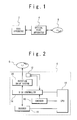
- Fig. 1 is a block diagram showing the configuration of the data recording system of the present invention.
- the data recording system is provided with a host apparatus 2 and an optical disc apparatus 4.
- the optical disc apparatus 4 is set with an optical disc medium 6 such as a DVD disc, and records a data on the optical disc medium 6 or reproduces the data from the optical disc medium, in accordance with a command from the host apparatus 2. Also, the optical disc apparatus 4 carries out a training process for checking and adjusting a record condition in response to a command from the host apparatus 2 prior to starting the write operation.
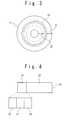
- Fig. 2 is a block diagram showing the configuration of the optical disc apparatus 4 according to the first embodiment of the present invention.
- the optical disc apparatus 4 of the first embodiment is provided with a CPU 10, an access section 12, a disc controller 14, an encoder 16, a decoder 18 and a rotation driving system 20.
- the CPU 10 controls the entire operation of the optical disc apparatus 4.
- the CPU 10 exchanges commands, notices and data with the host apparatus 2, and controls the disc controller 14, the encoder 16 and the decoder 18, and also carries out a necessary calculation.
- the CPU 10 output a dummy data of a predetermined bit pattern to the encoder 16.
- the access section 12 contains a laser diode, uses a laser beam to write a data onto the optical disc medium 6 and reproduces the data from the optical disc medium 6.
- the access section 12 is well known to a skilled person in the art.
- the rotation driving system 20 drives the optical disc medium 6 in response to a command from the CPU 10 so that the optical disc medium 6 is rotated, when the optical disc medium 6 is set.
- the disc controller 14 controls the access section 12 and the rotation driving system 20 such that the optical disc medium 6 is rotated, a laser control is carried out and the recording and reproducing operations are carried out.
- the disc controller 14 drives the rotation driving system 20 to rotate the optical disc medium 6 in accordance with a command from the CPU 10. Also, the disc controller 14 controls the position of the access section 12 in accordance with a command from the CPU 10, and also controls the operation of the access section 12 in the recording and reproducing operations.
- the disc controller 14 controls the access section 12 to read a data necessary to carry out the recording operation from the optical disc medium 6, and to record the data sent from the encoder 16 onto the optical disc medium 6 based on the read-out necessary data.
- the access section 12 outputs the laser beam to record the data onto the optical disc medium 6. Also, in the reproducing operation, the disc controller 14 controls the access section 12 to reproduce the data from the optical disc medium 6. The access section 12 outputs the laser beam to reproduce the data from the optical disc medium 6. The reproduced data is sent through the disc controller 14 to the decoder 18.
- the encoder 16 carries out an encoding process on a user data and the dummy data in response to a command from the CPU 10. For example, in case of the DVD, the encoder generates a record data in units of ECC (error correction code) blocks, each of which includes 16 sectors. The generated record data is sent to the access section 12 through the disc controller 14. A configuration in which the ECC block is extended to 32 sectors is proposed in a next generation DVD.
- ECC error correction code
- the decoder 18 carries out a decoding process of the data reproduced from the optical disc medium 6 in units of the ECC blocks in response to a command from the CPU 10.
- a spiral groove track for tracking is formed on an optical disc substrate.
- a multi-layer recording layer made of an organic material and the like is formed thereon.
- the laser beam of high power is focused on this recording layer to partially change the recording layer and to form record pits.
- the data is recorded on the optical disc medium 6.
- the optical disc medium 6 after the recording operation has the same data format as that of the embossed optical disc ROM medium (DVD-ROM or the like). Also, since a servo signal having the substantially same characteristics as the optical disc ROM medium can be obtained, the recorded data can be reproduced from the optical disc medium 6 by an optical apparatus dedicated to the reproduction.
- Fig. 3 is a diagram showing the format of the recording type optical disc medium 6.
- the recording type optical disc medium 6 has a system area 22, a data area 23 and a lead-out area (not shown) in a concentric manner from the inner circumference side.
- the system area 22 is used to record a system data necessary for the recording and reproducing operations, including a disc data and a data indicative of a user data area in which a user data is recorded.
- An area in which a record control data is recorded to control the optical disc medium and an area used to check a record condition are secured in the system area 22.
- the lead-out area indicates the end of the storage area on the optical disc medium 6. When the lead-out area is detected, it is recognized that the recording operation of the data is not ended on the optical disc medium 6, and cannot be carried out.
- the data area 23 is located between the system area 22 and the lead-out area and is used to record the user data.
- a spiral recording track 24 is formed in the data area 23.
- Fig. 4 shows the area arrangement on the disc 6 along the radius direction. Referring to Fig. 4, the area arrangement will be described below.
- the left side indicates the inner circumference side of the disc 6, and the right side indicates the outer circumference side thereof.
- the system area 22 on the inner circumference side includes a system control data necessary when the optical disc apparatus 4 carries out the recording and reproducing operations, and an arrangement data of recorded data on the optical disc medium 6.
- the system area 22 is roughly classified into three areas of a test record area 26, a record control data area 27 and a user data lead-in area 28.
- the user data lead-in area 28 is arranged on the side closest to the data area 23. This area is used to record a system control data necessary when already recorded data is reproduced from the recording type optical disc medium 6 by the optical disc apparatus dedicated to reproduction. That is, an arrangement of the user data is recorded in the user data lead-in area 28.
- the record control data area 27 is used to record a record control data about portions of the data area 23, i.e., a data necessary for the optical disc apparatus 4 to record user data in the data area 23.
- the record control data contains a data associating with a next recordable position in the data area 23, and the usage situation of the test record area 26.
- the data of the record control data area 27 is sequentially updated and increased.
- a new record control data is additionally recorded in a predetermined unit from the inner circumference side to the outer circumference side.
- the test record area 26 is used for a trial recording operation to check the condition optimal to the recording operation.
- the trial recording is carried out while a power, a record waveform and the like are changed.
- the inside of the test record area 26 may be used in any order, typically, the outer circumference side is firstly used in many cases.
- a border area is provided prior to the ending such that the apparatus dedicated to the reproduction can reproduce the recorded user data, namely, compatibility with the apparatus dedicated to the reproduction can be attained.
- An area segmented by the border areas is referred to as a bordered area.
- Fig. 5 shows an arrangement of various areas in the optical disc medium 6. Referring to Fig. 5, the arrangement of various areas will be described below.
- the system area 22 includes a test record area (not shown), a record control data area 27, and a user data lead-in area 28.
- bordered areas 31-1 to 31-2 are separated and arranged by border areas 32-1 to 32-2.
- border areas 32-1 to 32-2 are separated and arranged by border areas 32-1 to 32-2.
- the two bordered areas are illustrated. However, it is not limited to the two areas.
- a lead-out area 34 is arranged following the border area 32-2 to indicate the completion of the record in the optical disc medium 6.
- the user data is recorded until the bordered area 31-2.
- the recording is not performed. That is, a non-recorded area 36 is arranged following the lead-out area 34.
- This lead-out area 34 indicates the end of the data recorded area on the optical disc medium 6.
- the lead-out area 34 is detected at the time of the reproduction, the end of the data area on the optical disc medium 6 is recognized by the optical disc apparatus 4.
- a large capacity of lead-out area was provided as a guard area in accordance with the specification of the ROM.
- the lead-out area 34 was provided to have a size equal to or larger than the border area 32-2.
- the border area 32-2 indicates that the bordered area 31-2 is closed, and determines a data capacity required for the apparatus dedicated to the reproduction to reproduce the data of the bordered area 31-2. Therefore, an area with a size equal to or less than the border area 32-2 is assigned to the lead-out area 34, so that to the apparatus dedicated to the reproduction can recognize the end of the data recorded area on the optical disc medium 6. If the lead-out area is small, the time of the finalizing process can be made shorter.
- the user data is recorded from the inner circumference side to the outer circumference side.
- the user data is recorded in the bordered area 31-1 on the innermost circumference (Step S13). This recording is continued until the user data to be recorded in the bordered area 31-1 has been ended (Step S15-NO). If the recording operation of the user data in the bordered area 31-1 has been ended (Step S15-YES), a border closing process is carried out. In the border closing process, a border lead-out is recorded in the border area 32-1, to indicate the fact that the recording operation of the bordered area 31-1 has been ended (Step S17).
- Step S19-NO When an additional recording operation is further carried out (Step S19-NO) after the bordered area 31-1 is closed, a border lead-in is recorded in the border area 32-1 and a next user data is recorded in the next bordered area 31-2.
- Step S13 When the user data is recorded in the final bordered area 31-2 in the optical disc medium 6 (Step S13), a border lead-out is recorded in the border area 32-2, and the border closing process is carried out.
- Step S19-YES When the additional recording operation is not carried out on the optical disc medium 6 (Step S19-YES), a disc closing process is carried out in response to an instruction from the host apparatus 2.
- a user data lead-out is recorded in a lead-out area 34 following the border area 32-2 (Step S21).
- the user data lead-out only indicates the fact that the recording operation in the optical disc medium 6 has been completed.
- the size of the lead-out area 34 may be smaller than the border area 32-2.
- the finalizing data used for the user data lead-out is not limited and is enough to indicate completion of the recording operation.
- the width of the user data lead-out in the radius direction of the optical disc medium is 500 ⁇ m or more.
- the width of the bordered area in the radius direction is approximately several 100 ⁇ m.
- the width of the radius direction of the bordered area is approximately 50 to 100 ⁇ m, this is acknowledged to be sufficient.
- the bordered area of 50 ⁇ m in the minimum is set, the user data lead-out can be similarly set to 50 ⁇ m.
- the system area 22 includes the test record area (not shown), the record control data area 27, and the user data lead-in area 28.
- the bordered areas 31-1 to 31-2 are separated by the border areas 32-1 to 32-2.
- the non-recorded area 36 follows on the outer circumference side of the bordered area 31-2.
- only the two bordered areas are illustrated. However, it is not limited to the two areas.
- the lead-out area for indicating the completion of the recording operation into the optical disc medium 6 is not provided, and a data indicating that the border area 32-2 is the final bordered area in the optical disc medium 6 is recorded in, for example, the record control data area 27 of the system area 22.
- the apparatus dedicated to the reproduction can stop the reproducing operation at the point where the data indicating the final bordered area is obtained, when the reproducing operation is repeated.
- the final bordered area namely, the final area of the recording can be detected without any user data lead-out indicating the end of the recording of the optical disc medium 6.
- the user data is recorded from the inner circumference side to the outer circumference side.
- the user data is recorded in the bordered area 31-1 on the innermost circumference (Step S33). This recording is continued until the user data to be recorded in the bordered area 31-1 has been ended (Step S35-NO). If the recording operation of the user data in the bordered area 31-1 has been ended (Step S35-YES), the recording operation of a next user data is instructed by the host apparatus 2. Consequently, if the recording operation into the optical disc medium 6 is determined to be continued (Step S37-NO), the border closing process is carried out. In the border closing process, the border lead-out is recorded in the border area 32-1, and indicates the fact that the recording operation of the bordered area 31-1 has been ended (Step S39).
- the border lead-in is recorded in the border area 32-1, and the user data is recorded in the next bordered area 31-2 (Step S33).
- the host apparatus 2 sends to the optical disc apparatus 4, an instruction for indicating that there is no additional record, together with the end of the recording of the user data.
- the disc closing process is carried out.
- the border lead-out is recorded in the border area 32-2 following the bordered area 31-2, and then the data of the border area 32-2 as the final bordered area is recorded in the system area 22.
- the data of the final bordered area is preferably recorded in the record control data area 27 of the system area 22 where the data of the various bordered areas are recorded.
- a process required as the finalizing process is carried out to record a dummy data in the non-recorded portion of the system area 22.
- the fact that the optical disc medium 6 is finalized can be indicated without the lead-out area 34. For this reason, the processing time when the user data lead-out is recorded in the lead-out area 34 can be reduced, which can reduce the time of the recording in the optical disc medium 6.
- the record control data may be recorded not only in the system area, but also in an area provided at the inner circumference end of each bordered area.
- a data of border lead-out to be recorded in the border area 32-2 may be used as a finalizing data to indicate the final portion of the data recording. In this case, it is not necessary to record the data in the system area 22 to indicate the final border area. If this design is employed, the area to be recorded can be further reduced.
- the lead-out area 34 the data area where the user data can be recorded can be extended.
Landscapes
- Engineering & Computer Science (AREA)
- Architecture (AREA)
- Civil Engineering (AREA)
- Structural Engineering (AREA)
- Optical Recording Or Reproduction (AREA)
- Signal Processing For Digital Recording And Reproducing (AREA)
Applications Claiming Priority (2)
| Application Number | Priority Date | Filing Date | Title |
|---|---|---|---|
| JP2004129085A JP4237092B2 (ja) | 2004-04-23 | 2004-04-23 | 光ディスク装置、光ディスク情報記録方法及び光ディスク媒体 |
| JP2004129085 | 2004-04-23 |
Publications (2)
| Publication Number | Publication Date |
|---|---|
| EP1589526A2 true EP1589526A2 (de) | 2005-10-26 |
| EP1589526A3 EP1589526A3 (de) | 2007-04-04 |
Family
ID=34939435
Family Applications (1)
| Application Number | Title | Priority Date | Filing Date |
|---|---|---|---|
| EP05103245A Withdrawn EP1589526A3 (de) | 2004-04-23 | 2005-04-21 | Optisches Aufzeichnungsmedium, Vorrichtung und Verfahren zur Aufzeichnung von Daten auf dieses Medium |
Country Status (6)
| Country | Link |
|---|---|
| US (1) | US20050237874A1 (de) |
| EP (1) | EP1589526A3 (de) |
| JP (1) | JP4237092B2 (de) |
| KR (1) | KR100702271B1 (de) |
| CN (1) | CN100492515C (de) |
| TW (1) | TW200603118A (de) |
Cited By (1)
| Publication number | Priority date | Publication date | Assignee | Title |
|---|---|---|---|---|
| EP1796092A3 (de) * | 2005-12-08 | 2009-04-01 | NEC Corporation | Aufzeichnungsvorrichtung für optische Platten und optisches Plattenmedium |
Families Citing this family (5)
| Publication number | Priority date | Publication date | Assignee | Title |
|---|---|---|---|---|
| JP4273705B2 (ja) | 2002-05-13 | 2009-06-03 | 日本電気株式会社 | 光ディスク媒体 |
| JP2005209322A (ja) | 2003-12-26 | 2005-08-04 | Nec Corp | 光ディスク装置、光ディスク情報記録方法及び光ディスク媒体 |
| JP4102775B2 (ja) | 2004-04-23 | 2008-06-18 | 日本電気株式会社 | 光ディスク装置、光ディスク情報記録方法及び光ディスク媒体 |
| JP2007257686A (ja) | 2006-03-20 | 2007-10-04 | Nec Corp | 書き換え型光ディスク記録方法及び光ディスクドライブ装置 |
| JP2007323695A (ja) * | 2006-05-30 | 2007-12-13 | Nec Corp | 書き換え型光ディスクの記録制御方法およびその記録再生用のドライブ装置 |
Family Cites Families (28)
| Publication number | Priority date | Publication date | Assignee | Title |
|---|---|---|---|---|
| US5701281A (en) * | 1995-07-13 | 1997-12-23 | Nec Corporation | Optical disk device capable of recording a control parameter on unused optical disk area |
| US5940853A (en) * | 1996-02-23 | 1999-08-17 | Matsushita Electric Industrial Co., Ltd. | Recording and reproducing apparatus enabling modification of data recorded on a non-erasable recording medium |
| JP3991369B2 (ja) * | 1996-04-11 | 2007-10-17 | 松下電器産業株式会社 | 光ディスク |
| JPH10112166A (ja) * | 1996-10-04 | 1998-04-28 | Sony Corp | 光ディスクのファイナライゼーション方法および光ディスクのファイナライゼーション装置 |
| KR100491233B1 (ko) * | 1996-10-07 | 2005-05-25 | 마츠시타 덴끼 산교 가부시키가이샤 | 광 디스크, 광 디스크 장치 및 광 디스크 기록 방법 |
| US6163521A (en) * | 1997-04-16 | 2000-12-19 | Matsushita Electric Industrial Co., Ltd. | Disk having read-only and read-write areas |
| ID21519A (id) * | 1997-09-17 | 1999-06-24 | Matsushita Electric Industrial Co Ltd | Peralatan editing data video dan medium rekaman yang dapat dibaca komputer menyimpan suatu program editing |
| GB2336021B (en) * | 1998-04-01 | 2000-05-03 | Ricoh Kk | Optical-disc recording device |
| WO2000019432A1 (en) * | 1998-09-25 | 2000-04-06 | Matsushita Electric Industrial Co., Ltd. | Information recording medium, information recording/reproducing method, and information recording/reproducing device |
| JP3478159B2 (ja) * | 1999-03-29 | 2003-12-15 | ヤマハ株式会社 | 光ディスクのディスク情報取得方法、アクセス制御方法、記録制御方法および光ディスク記録装置 |
| JP3783909B2 (ja) * | 1999-05-20 | 2006-06-07 | パイオニア株式会社 | カッティング装置、情報記録媒体、情報記録装置及び情報記録方法並びに、カッティング方法 |
| ATE453289T1 (de) * | 1999-09-10 | 2010-01-15 | Pioneer Corp | Verfahren und vorrichtung zur informationsaufzeichnung und -wiedergabe |
| BR0007227A (pt) * | 1999-10-20 | 2001-09-25 | Koninkl Philips Electronics Nv | Portador de gravação de um tipo só de leitura, processo de fabricar um portador de gravação de um tipo só para leitura, e, dispositivo de leitura para ler um portador de gravação de um tipo só para leitura |
| JP2001266495A (ja) * | 2000-03-24 | 2001-09-28 | Sony Corp | 光ディスク及び光ディスク駆動装置 |
| JP2002015549A (ja) * | 2000-06-26 | 2002-01-18 | Sony Corp | 記録再生装置及び記録再生方法 |
| JP4806839B2 (ja) * | 2000-07-19 | 2011-11-02 | ソニー株式会社 | 記録装置、記録方法 |
| US6628602B2 (en) * | 2000-07-27 | 2003-09-30 | Victor Company Of Japan | Optical information recording medium |
| KR100475604B1 (ko) * | 2001-03-09 | 2005-03-10 | 엘지전자 주식회사 | 재생전용 광디스크와, 그 재생전용 광디스크 장치에서의재생방법 |
| US7023775B2 (en) * | 2001-03-22 | 2006-04-04 | Matsushita Electric Industrial Co., Ltd. | Recording apparatus and method, and reproduction apparatus and method for recording data to or reproducing data from a write once type information recording medium, and write once type information recording medium |
| ES2348906T3 (es) * | 2001-04-24 | 2010-12-16 | Koninklijke Philips Electronics N.V. | Dispositivo y procedimiento para grabar. |
| JP3559540B2 (ja) * | 2001-09-07 | 2004-09-02 | 株式会社東芝 | 多目的情報記憶媒体及び記憶方法及び再生方法及び再生装置 |
| KR100716962B1 (ko) * | 2001-09-29 | 2007-05-10 | 삼성전자주식회사 | 광디스크 |
| JP3797191B2 (ja) * | 2001-10-25 | 2006-07-12 | 株式会社日立製作所 | 情報記録装置 |
| CA2478533C (en) * | 2002-03-05 | 2013-02-05 | Koninklijke Philips Electronics N.V. | Device, record carrier and method for recording information |
| JP4606693B2 (ja) * | 2002-11-22 | 2011-01-05 | ソニー株式会社 | 光ディスク、記録装置、再生装置、記録方法、再生方法 |
| JP4870554B2 (ja) * | 2003-03-13 | 2012-02-08 | サムスン エレクトロニクス カンパニー リミテッド | データ領域管理の可能な追記型ディスク、追記型ディスクのデータ領域の管理方法、データ記録装置、データの再生方法及びその装置 |
| JP2005122774A (ja) * | 2003-10-14 | 2005-05-12 | Nec Corp | 記録型光ディスク装置および光ディスク媒体 |
| JP2005209322A (ja) * | 2003-12-26 | 2005-08-04 | Nec Corp | 光ディスク装置、光ディスク情報記録方法及び光ディスク媒体 |
-
2004
- 2004-04-23 JP JP2004129085A patent/JP4237092B2/ja not_active Expired - Fee Related
-
2005
- 2005-04-21 CN CNB2005100673642A patent/CN100492515C/zh not_active Expired - Fee Related
- 2005-04-21 TW TW094112717A patent/TW200603118A/zh unknown
- 2005-04-21 EP EP05103245A patent/EP1589526A3/de not_active Withdrawn
- 2005-04-21 KR KR1020050033014A patent/KR100702271B1/ko not_active Expired - Fee Related
- 2005-04-22 US US11/111,758 patent/US20050237874A1/en not_active Abandoned
Cited By (1)
| Publication number | Priority date | Publication date | Assignee | Title |
|---|---|---|---|---|
| EP1796092A3 (de) * | 2005-12-08 | 2009-04-01 | NEC Corporation | Aufzeichnungsvorrichtung für optische Platten und optisches Plattenmedium |
Also Published As
| Publication number | Publication date |
|---|---|
| US20050237874A1 (en) | 2005-10-27 |
| JP2005310321A (ja) | 2005-11-04 |
| CN1691180A (zh) | 2005-11-02 |
| KR20060047309A (ko) | 2006-05-18 |
| KR100702271B1 (ko) | 2007-03-30 |
| JP4237092B2 (ja) | 2009-03-11 |
| CN100492515C (zh) | 2009-05-27 |
| EP1589526A3 (de) | 2007-04-04 |
| TW200603118A (en) | 2006-01-16 |
Similar Documents
| Publication | Publication Date | Title |
|---|---|---|
| US7474599B2 (en) | Optical disc medium, and apparatus and method for recording data on the same | |
| US20050141351A1 (en) | Recording type optical disk apparatus and optical disk medium | |
| US7471617B2 (en) | Optical disc medium having extended record control data areas, optical disc apparatus using the same, and data recording method on the same | |
| JP2002279649A (ja) | 記録媒体及び信号記録方法及び装置及び再生装置 | |
| US20050169147A1 (en) | Recording-medium evaluation method, recording/reproduction apparatus and recording medium | |
| EP1589526A2 (de) | Optisches Aufzeichnungsmedium, Vorrichtung und Verfahren zur Aufzeichnung von Daten auf dieses Medium | |
| US7440375B2 (en) | Information recording device and method | |
| JP4278855B2 (ja) | 書換え可能型光ディスクならびにその製造方法および製造システム | |
| US7933192B2 (en) | Information recording medium, information recording apparatus and method, and computer program | |
| KR100675582B1 (ko) | 광디스크 기록/재생 방법 및 기록/재생 장치, 그리고광디스크 | |
| US7430157B2 (en) | Recording device, recording method, reproducing device, and reproducing method | |
| JP3425376B2 (ja) | 光情報記録媒体、情報記録方法及びその装置 | |
| US7539104B2 (en) | Information recording medium with superposed first and second recording layers | |
| US20050237877A1 (en) | Optical disc medium, optical disc apparatus using the same, and data recording method on the same | |
| US7283456B2 (en) | Reproduction-only recording medium | |
| KR100965882B1 (ko) | 정보 저장매체, 데이터의 기록/재생 방법 및 장치 | |
| JP4145853B2 (ja) | 記録媒体がオリジナル媒体か複製媒体かを判定する方法、プログラム、コンピュータ読み取り可能な記録媒体 | |
| EP1796092A2 (de) | Aufzeichnungsvorrichtung für optische Platten und optisches Plattenmedium | |
| JP2005259272A (ja) | 光ディスク記録方法及び、光ディスク記録再生装置 | |
| MXPA99003772A (en) | Optical disc |
Legal Events
| Date | Code | Title | Description |
|---|---|---|---|
| PUAI | Public reference made under article 153(3) epc to a published international application that has entered the european phase |
Free format text: ORIGINAL CODE: 0009012 |
|
| AK | Designated contracting states |
Kind code of ref document: A2 Designated state(s): AT BE BG CH CY CZ DE DK EE ES FI FR GB GR HU IE IS IT LI LT LU MC NL PL PT RO SE SI SK TR |
|
| AX | Request for extension of the european patent |
Extension state: AL BA HR LV MK YU |
|
| PUAL | Search report despatched |
Free format text: ORIGINAL CODE: 0009013 |
|
| AK | Designated contracting states |
Kind code of ref document: A3 Designated state(s): AT BE BG CH CY CZ DE DK EE ES FI FR GB GR HU IE IS IT LI LT LU MC NL PL PT RO SE SI SK TR |
|
| AX | Request for extension of the european patent |
Extension state: AL BA HR LV MK YU |
|
| RAP1 | Party data changed (applicant data changed or rights of an application transferred) |
Owner name: KABUSHIKI KAISHA TOSHIBA Owner name: NEC CORPORATION |
|
| 17P | Request for examination filed |
Effective date: 20070926 |
|
| 17Q | First examination report despatched |
Effective date: 20071022 |
|
| AKX | Designation fees paid |
Designated state(s): DE FR GB |
|
| STAA | Information on the status of an ep patent application or granted ep patent |
Free format text: STATUS: THE APPLICATION IS DEEMED TO BE WITHDRAWN |
|
| 18D | Application deemed to be withdrawn |
Effective date: 20090421 |