EP1589409A2 - System und Verfahren zum Ausrichten von Gegenständen unter Verwendung einer nicht-linearen Zeigerbewegung - Google Patents
System und Verfahren zum Ausrichten von Gegenständen unter Verwendung einer nicht-linearen Zeigerbewegung Download PDFInfo
- Publication number
- EP1589409A2 EP1589409A2 EP05103171A EP05103171A EP1589409A2 EP 1589409 A2 EP1589409 A2 EP 1589409A2 EP 05103171 A EP05103171 A EP 05103171A EP 05103171 A EP05103171 A EP 05103171A EP 1589409 A2 EP1589409 A2 EP 1589409A2
- Authority
- EP
- European Patent Office
- Prior art keywords
- pointer
- movement
- projected
- alignment area
- coordinate position
- Prior art date
- Legal status (The legal status is an assumption and is not a legal conclusion. Google has not performed a legal analysis and makes no representation as to the accuracy of the status listed.)
- Withdrawn
Links
Images


Classifications
-
- G—PHYSICS
- G06—COMPUTING OR CALCULATING; COUNTING
- G06F—ELECTRIC DIGITAL DATA PROCESSING
- G06F3/00—Input arrangements for transferring data to be processed into a form capable of being handled by the computer; Output arrangements for transferring data from processing unit to output unit, e.g. interface arrangements
- G06F3/01—Input arrangements or combined input and output arrangements for interaction between user and computer
- G06F3/048—Interaction techniques based on graphical user interfaces [GUI]
- G06F3/0481—Interaction techniques based on graphical user interfaces [GUI] based on specific properties of the displayed interaction object or a metaphor-based environment, e.g. interaction with desktop elements like windows or icons, or assisted by a cursor's changing behaviour or appearance
-
- G—PHYSICS
- G06—COMPUTING OR CALCULATING; COUNTING
- G06F—ELECTRIC DIGITAL DATA PROCESSING
- G06F3/00—Input arrangements for transferring data to be processed into a form capable of being handled by the computer; Output arrangements for transferring data from processing unit to output unit, e.g. interface arrangements
- G06F3/01—Input arrangements or combined input and output arrangements for interaction between user and computer
- G06F3/048—Interaction techniques based on graphical user interfaces [GUI]
- G06F3/0481—Interaction techniques based on graphical user interfaces [GUI] based on specific properties of the displayed interaction object or a metaphor-based environment, e.g. interaction with desktop elements like windows or icons, or assisted by a cursor's changing behaviour or appearance
- G06F3/04812—Interaction techniques based on cursor appearance or behaviour, e.g. being affected by the presence of displayed objects
Definitions
- the present invention relates in general to an improved graphical user interface. More specifically the present invention relates to an improved system and method of aligning objects in a graphical user interface.
- GUI graphical user interface
- I/O input/output
- a user employs an input device, such as a mouse or trackball, to manipulate and relocate a pointer on the computer display.
- GUI graphical display elements
- GUI objects graphical display elements
- users want to align GUI objects in order to perform a desired function or create documents with specific characteristics. For example, to create a document with a professional appearance, users may want to align GUI objects at the same vertical or horizontal position.
- One alignment task that is particularly common is “stacking" GUI objects so they are aligned in succession on a computer display.
- GUI objects using a "click and drag" technique where a single pointer event such as a button click selects the GUI object. Once the GUI object is selected, the pointer moves the GUI object to a new location where a second pointer event places the GUI object.
- dragging aligning two or more GUI objects is often difficult to accomplish, leading to frustration and lowered productivity.
- users with diminished visual or physical abilities, or lack of training have difficulty correctly positioning the dragged object.
- pointer positioning difficulty may be attributable to the computer device.
- a user may not place a GUI object close to, but not at, the aligned coordinate position without the object "snapping" to the aligned coordinate position.
- Another drawback to this approach is that a user must activate the snapping option by, for example, selecting a menu item from a pull-down menu. Some users may not know that options such as "snapping" are available, and may continue to use the "click and drag” technique. As described above, this approach leads to frustration because users are often required to repetitively re-adjust the position of the pointer in order to accurately place the object being dragged.
- pointer movement on a computer display is proportional to the input received from an input device (i.e., trackball, mouse, etc.).
- the present invention is generally directed to aligning GUI objects with pointer movement that is not proportional to input received from an input device. More specifically, embodiments of the present invention provide a system, method, and computer-readable medium that adjust pointer movement when a pointer with a selected GUI object is intersects with an alignment area.
- the alignment areas are derived from specified locations in GUI objects such as a connection point or shape vertices. Since each GUI object has different locations that designate an aligned coordinate position, alignment areas vary depending on the GUI objects being aligned.
- pointer movement is adjusted so that a proportionally larger amount of input is required to affect movement of the pointer. For example, a larger amount of input device movement is required to move the pointer an incremental distance on a computer display. From the user's perspective, alignment areas have "friction" in that the pointer is less responsive when compared to other areas of the computer display.
- One embodiment of the present invention is a method that adjusts pointer movement when input causes the pointer to intersect one or more alignment areas.
- the method is implemented by a set of event-driven routines that determine if the projected movement of the pointer will intersect an alignment area. If the projected movement does not intersect an alignment area, already realized pointer positioning software computes the coordinate position of the pointer. Conversely, if the projected movement does intersect an alignment area, the method computes an adjusted coordinate position for the pointer. The calculation adjusts the pointer movement so that a proportionally larger amount of input is required to affect movement of the pointer in the alignment area.
- a computer device that adjusts pointer movement when input causes the pointer to intersect one or more alignment areas.
- the computer device includes an operating system in communication with various components including an input device, a computer display, a movement adjustment module, and one or more application programs.
- the movement adjustment module is configured to adjust the coordinate position of the pointer when it intersects one or more alignment areas.
- a computer-readable medium is provided with contents, i.e., a program that causes a computer device to operate in accordance with the method described herein.
- Embodiments of the present invention provide a system, method, and computer-readable medium that adjusts pointer movement when an input device causes a pointer to intersect one or more alignment areas.
- a pointer is a pictorial depiction used to input information into a computer device and is typically represented with an arrow.
- pointers may be represented with any pictorial depiction capable of identifying a "hot spot" on a computer display.
- pointer movement is adjusted to assist users align GUI objects.
- a proportionally larger amount of input i.e., a greater amount of pointer input device movement
- small movement of an input device does not cause the pointer to leave an alignment area.
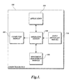
- FIGURE 1 provides an exemplary overview of a computer device 100 in which embodiments of the invention may be implemented.
- the computer device 100 includes a computer display 102, an operating system 104, a movement adjustment module 106, an application 108, and an input device 110.
- the computer device 100 may be any one of a variety of devices including, but not limited to, personal computer devices, server-based computer devices, personal digital assistants, cellular telephones, other electronic devices having some type of memory, and the like.
- FIGURE 1 does not show some of the typical components of many computer devices such as memory, keyboard, central processing unit, and the like.
- the operating system 104 may be a general-purpose operating system such as a Microsoft® operating system, UNIX® operating system, or Linux® operating system. As known to those skilled in the art and others, the operating system 104 controls the general operation of the computer device 100 and is responsible for management of hardware and basic system operations, as well as running applications. More specifically, the operating system 104 ensures that computer programs, such as application 108, are able to use hardware resources. As illustrated in FIGURE 1, the operating system 104 communicates with the computer display 102 which may include typical display devices, such as a monitor (e.g., CRT or LCD screen), a television, etc. The computer display 102 is suitable to display a pointer and other GUI objects.
- a monitor e.g., CRT or LCD screen
- the computer display 102 is suitable to display a pointer and other GUI objects.
- the computer device 100 is configured to execute computer programs such as application 108, which causes GUI objects to be displayed on the computer display 102.
- Application 108 may be any computer program which displays GUI objects including, but not limited to, editors, word processors, spreadsheets, browsers, computer-aided design, and the like.
- the input device 110 interacts with a user and the operating system 104 to specify event-driven routines to execute.
- the input device 110 may be any device capable of controlling a pointer on the computer display 102 including a mouse, trackball, touch pad, etc.
- input device 110 may be contained within the same housing as the computer device 100. Such arrangements are commonly found where the computer device is a notebook computer.
- the user may operate the input device 110 to manipulate and relocate the pointer and activate the pointer at designated positions on the computer display 102.
- the operating system 104 monitors pointer movement and other pointer events and provides a mechanism for computer programs, such as application 108, to perform actions in response to these events.
- embodiments of the present invention are implemented by a set of event-driven routines located in the movement adjustment module 106.
- the movement adjustment module 106 is interconnected and able to communicate with the operating system 104.
- the operating system 104 notifies the movement adjustment module 106 when the input device 110 is generating pointer movement.
- the movement adjustment module 106 determines if the projected movement will intersect an alignment area, which may be a grid point, handle, connection point, shape vertices, shape extension, or any other area of the computer display capable of aligning GUI objects. If the projected movement does intersect an alignment area, the movement adjustment module 106 adjusts pointer movement so that GUI objects may easily be aligned.
- the operating system 104 receives adjusted coordinate positions from the movement adjustment module 106 and causes the computer display 102 to display the pointer at the adjusted coordinates.
- the computer device When software formed in accordance with the invention is implemented in a computer device, for example of the type illustrated in FIGURE 1, the computer device provides a way for users to easily align GUI objects. Allowing a user to easily align GUI objects enhances the computer experience by making computer programs easier to use.
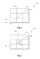
- FIGURE 2 For illustrative purposes, a representative section of computer display is depicted in FIGURE 2.
- FIGURE 2 is a pictorial depiction of a sample section of computer display 200 that contains a set of highly magnified pixels.
- the sample section of computer display 200 contains pixels 202, 204, 206, a pointer 208, and a path 210 that represents pointer 208 movement.
- a user employed input device such as input device 110, is used to relocate the pointer 208 across pixels 202, 204, and 206.
- the pointer 208 movement illustrated in FIGURE 2 is proportional to the input generated by the user.
- FIGURE 3 illustrates the sample section of computer display 200 depicted in FIGURE 2 wherein pixel 204 is designated as an alignment area in accordance with the present invention.
- a user employed input device such as input device 110
- input device 110 is used to relocate the pointer 208 across pixel 202.
- embodiments of the present invention adjust movement of the pointer so that a proportionally greater amount of input (i.e., mouse distance movement) is required to cause a predetermined amount of pointer movement.
- the ratio of mouse distance movement to point distance movement changes.
- the amount of mouse or other input device distance movement required to traverse pixel 204 is three times greater than the amount required to traverse other areas of the computer display 200.
- the path 300 generated by the pointer 208 in FIGURE 3 is representative of the same amount of input (i.e., mouse movement) as depicted by the path 210 in FIGURE 2.
- pixel 204 has "friction" in that pointer movement requires more input (i.e., mouse distance movement) across pixel 204 compared to other areas of the computer display 200.
- FIGURE 4 is an alternative illustration of the sample section of computer display 200 depicted in FIGURES 2-3 wherein pixel 204 is designated as an alignment area. Similar to FIGURE 3, a user employs an input device to traverse a portion of the computer display 200. However, in this illustrative embodiment of the present invention the pointer position is adjusted so that the input required to traverse pixel 204 is six times greater than the input required to traverse other areas of the computer display 200.
- the path 400 generated by the pointer 208 in FIGURE 4 is representative of the same amount of input (i.e., mouse distance movement) as depicted by the path 210 in FIGURE 2 and the path 300 in FIGURE 3.
- the degree with which an alignment area resists pointer movement may vary based on the use of the invention. For example, if a GUI is designed specifically for users with diminished visual or physical abilities, alignment areas may be implemented with a high friction factor in order to compensate for the reduced abilities of the users.
- FIGS 5-8 other exemplary aspects of the present invention will be described. For the sake of convenience, much of the description herein is provided in the context of specific GUI objects, but it should be well understood that the present invention is applicable to other GUI objects. Thus, references herein to specific GUI objects are only illustrative and should not be construed as limiting of the invention.
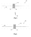
- FIGURE 5 illustrates a mechanism implemented by many computer programs commonly referred to as a slider 500.
- the slider 500 comprises more than one GUI object including a control button 502, a scale 504, and one or more scale indicators including scale indicator 506.
- the slider 500 is operated by a user selecting the control button 502 with the pointer 208 and moving the control button 502 along the scale 504.
- a slider 500 controls the value of a variable such as the volume level of sound played by speakers connected to a personal computer. Since users may not be able to easily position the pointer 208 at the values represented by scale indicators, such as scale indicator 506, systems have been developed to assist users in aligning the control button 502.
- One system, illustrated in FIGURE 5 is commonly referred to as snapping.
- control button 502 With snapping, the control button 502 is automatically moved (i.e., snapped) when located within a predetermined distance 508 to scale indicator 506.
- a disadvantage of snapping is that the control button 502 cannot be positioned within the predetermined distance 508. Thus, a section of the scale 504 is inert space not capable of being accessed.
- FIGURE 6 illustrates the slider 500 depicted in FIGURE 5 located in an alignment area created in accordance with the present invention. Similar to FIGURE 5, the user is able to select the control button 502 with the pointer 208 and move the control button 502 along the scale 504. Contrary to FIGURE 5, in order to assist users in aligning the control button 502 at the values close to the scale indicator 506, movement of the pointer 208 is adjusted. For a constant amount of input device movement, pointer 208 movement slows when the value represented by scale indicator 506 is achieved. Designating a region adjacent to a scale indicator 506 as an alignment area allows users to easily position the control button 502 close to the scale indicator 506 without snapping to the scale indicator location. Alignment of the control button 502 in this manner gives users access to additional positions along the scale 504.
- FIGURE 6 illustrates an aspect of the present invention in a one-dimensional environment where the vertical position of two GUI objects are aligned.
- FIGURES 7 and 8 illustrate an aspect of the present invention in a two-dimensional environment. More specifically, FIGURES 7 and 8 illustrate an activity performed in some computer programs commonly referred to as stacking.
- a GUI object 700 is shown located in an aligned position below a three-level stack of GUI objects 702, 704, and 706.
- the technique of snapping described above, is also applicable in two-dimensional environments. However, when snapping occurs in a two-dimensional environment, at least two predetermined areas become inert space that are not available for the positioning of GUI objects.
- a vertical axis predetermined distance 708 and a horizontal axis predetermined distance 710 are inaccessible for the positioning of GUI object 700.
- FIGURE 8 illustrates the GUI objects depicted in FIGURE 7 positioned such that GUI object 702 is located in a zone generally defined by vertical axis predetermined distance 708 and horizontal axis predetermined distance 710.
- Pointer movement is adjusted in the alignment area connection point 800 such that the pointer 208 slows down when the coordinate position of the connection point is achieved.
- visual, auditory, or visual feedback is provided to the user when the pointer 208 is located at the exact coordinate position as the connection point 800. The feedback indicates to the user that the GUI object 700 is properly aligned.
- FIGURE 8 illustrates one exemplary aspect of the present invention in the context of stacking GUI objects.
- a connection point 800 is designated as an alignment area that allows GUI objects to be more easily aligned.
- GUI objects may be aligned in other ways. For example, GUI objects may only be aligned vertically or horizontally, without touching, so that the GUI objects have the same x-coordinate or y-coordinate, respectively. Also, varying the size, shape, and location of alignment areas allows GUI objects to be more easily aligned at specific angles in relation to each other.
- aspects of the present invention may be implemented in combination with acquisition aids that guide a pointer to an alignment area.
- a more detailed explanation of a method, system, and computer-readable medium that guides a pointer to specific areas on a computer display may be found in commonly assigned, co-pending U.S. Patent Application No. 10/829,127 titled System and Method For Acquiring a Target With Intelligent Pointer Movement, filed concurrently herewith, the content of which is expressly incorporated herein by reference.
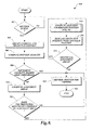
- FIGURE 9 is a flow diagram illustrating one exemplary embodiment of a pointer positioning method 900 formed in accordance with the present invention.
- the pointer positioning method 900 receives notice that an input device is generating pointer movement.
- the method 900 determines if the projected movement of the pointer will intersect an alignment area. If the projected movement does not intersect an alignment area, already realized (i.e., previously developed) pointer control software computes the new position of the pointer. Conversely, if the projected movement does intersect an alignment area, aspects of the present invention compute an adjusted position for the pointer.
- FIGURES 1-8 and the accompanying descriptions the exemplary pointer positioning method 900 illustrated in FIGURE 9 will now be described.
- the pointer positioning method 900 begins at block 902 where the method waits for a pointer movement event from an input device.
- input device 110 will generate a pointer movement event and communicate the event to the operating system 104 when moved by a user.
- existing systems allow event-driven routines to receive notice of pointer movement events and perform actions in response to the events.
- the event-driven routines of the present invention are implemented as callback functions, which are routines passed directly to the operating system 104 as parameters in a function call.
- execution of the pointer positioning method 900 is initiated by the operating system 104.
- the pointer positioning method 900 Upon receipt of a pointer movement event, the pointer positioning method 900 proceeds to block 904 where the method 900 obtains the current and projected position of the pointer.
- the coordinate position of a pointer is generally represented as a 2-tuple that includes an x-coordinate and a y-coordinate.
- One location on a computer display is designated as the origin with the value of the 2-tuple being (0,0).
- the pointer positioning method 900 obtains the current and projected coordinate positions of the pointer, the pointer's projected velocity is computed.
- the method 900 obtains the time interval for the pointer movement event received at block 902 and computes the pointer movement velocity using mathematical functions and computer-implemented routines generally known in the art.
- the pointer positioning method 900 proceeds to decision block 908 where the method 900 determines whether the pointer movement velocity computed at block 906 is higher than a predetermined threshold.
- pointer movement is not adjusted in an alignment area when the projected velocity of the pointer is higher than a predetermined threshold.
- the method 900 assumes that a user generating rapid pointer movement is not attempting to align a GUI object. If the projected pointer velocity is higher than the predetermined threshold, the method 900 proceeds to block 918 described below. Conversely, if projected pointer velocity is lower or equal to the predetermined threshold, the method 900 proceeds to decision block 910.
- the method 900 computes the coordinate positions on the computer display of the alignment areas.
- alignment areas are derived from specified locations in GUI objects such as a connection point or shape vertices. Since each GUI object has characteristics that determine an aligned coordinate position, alignment areas vary depending on the GUI objects being aligned. Also, the coordinate position of alignment areas (i.e. locations on the computer display where pointer movement in non-linear) depends on the pointer's position in relation to the selected GUI object. Thus, an offset value for the pointer is calculated that allows the method 900 to determine the location of the alignment areas.
- the method 900 determines whether the pointer movement event received at block 902 causes the pointer to intersect an alignment area.
- the present invention maintains an interface that allows computer programs, such as application 108, to define and use alignment areas. Aspects of the present invention track the shape, location, and size of all alignment areas on the computer display.
- the method 900 is able to determine whether the pointer movement event received at block 902 causes the pointer to intersect an alignment area by comparing the projected movement of the pointer with the coordinate positions occupied by alignment areas. If the projected movement of the pointer does not intersect an alignment area, the method 900 proceeds to block 920 described below. Conversely, if the projected movement of the pointer does intersect an alignment area, the method 900 proceeds to block 914.
- an aspect of the present invention computes an adjusted coordinate position for the pointer.
- the adjusted coordinate position is calculated.
- One embodiment of a method for calculating an adjusted pointer position in accordance with the present invention is described below with reference to FIGURES 10-12.
- the pointer positioning method 900 replaces the projected coordinate position of the pointer with the adjusted coordinate position calculated at block 914.
- the method communicates the adjusted coordinate position to the operating system 104 with software engineering techniques generally known in the art.
- the method 900 passes information to the operating system 104 that indicates whether the pointer intersected an alignment area so that computer programs that implement the present invention can provide visual, auditory, or tactile feedback to users when GUI objects are aligned.
- a test is conducted to determine whether the event received at block 902 causes the pointer to intersect another alignment area.
- the method 900 determines whether an event causes the pointer to intersect an alignment area by comparing the projected movement of the pointer with the shape, location, and size of existing alignment areas. Thus, when a pointer event causes the pointer to intersect multiple alignment areas, calculation of adjustment amounts occurs in the order of intersection. If the projected movement of the pointer does intersect another alignment area, the method 900 proceeds back to block 914 and blocks 914 through 918 are repeated until pointer movement is adjusted in all alignment areas. Conversely, if the projected movement of the pointer does not intersect another alignment area, the method 900 proceeds to block 920.
- the pointer is rendered for viewing at the coordinate position calculated at block 914. Since existing systems for rendering a pointer for viewing on a computer display are well known to those skilled in the art, the pointer rendering process is not described here. Then at block 922, the pointer positioning method 900 terminates.
- embodiments of the present invention are not limited to the method as shown in FIGURE 9. Some embodiments may include additional actions or eliminate some of the actions shown in FIGURE 9. For example, pointer movement may be adjusted regardless of pointer velocity. In this example, block 908, which determines whether the projected pointer movement is within a velocity threshold would be eliminated.
- FIGURE 10 is a flow diagram illustrating one exemplary embodiment of a calculation method 1000 formed in accordance with the present invention.
- the calculation method 1000 begins at block 1002 where the method 1000 determines the coordinate position where the pointer intersects an alignment area.
- aspects of the present invention receive the current and projected coordinate position of the pointer and track the size, shape, and location of alignment areas. With this information, the calculation method 1000 is able to calculate the coordinate position where the pointer intersects an alignment area using mathematical functions and computer implemented routines generally known in the art.
- the projected movement of the pointer is decomposed into directional components.
- the movement of any entity, such as a pointer is capable of being expressed mathematically as a vector.
- a vector is a quantity that has both a magnitude and a direction.
- pointer movement may be decomposed into a horizontal component and a vertical component which permits calculation of the change in pointer position in both the vertical and horizontal directions, respectively.
- the calculation method 1000 selects a directional component of the pointer's movement. For each directional component selected, the calculation method 1000 adjusts the projected movement of the pointer in the component direction.
- the calculation method 1000 adjusts the projected movement of the pointer in the component direction.
- much of the description herein is provided in the context of a two dimensional environment where adjustment occurs in the vertical direction and the horizontal direction.
- the present invention is also applicable in other environments, such as three-dimensional environments. References and examples herein to two-dimensional environments are only illustrative and should not be construed as limiting the applications of the invention.
- the calculation method 1000 obtains a directional friction curve that quantifies resistance to pointer movement in the alignment area that the pointer is projected to intersect.
- the amount that pointer movement is adjusted depends on three variables; (1) friction factor (2) alignment area size, and (3) shape of the friction curve.
- the friction factor is a variable that quantifies each pixel's resistance to pointer movement.
- the degree in which pixels resist pointer movement i.e., friction factor
- the friction factor may vary depending on attributes of pointer movement. For example, a user generating rapid pointer movement is less likely to be attempting to place a pointer on a target. Resistance to pointer movement may be dependent on another variable such as pointer velocity.
- Alignment area size (i.e., the number of pixels in a component direction) affects adjustment of pointer movement in that larger alignment areas cause greater total resistance to pointer movement than smaller alignment areas.
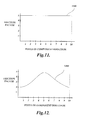
- Exemplary friction curves are illustrated in FIGURES 11-13 and discussed in greater detail below. In summary, a friction curve plots the size of an alignment area against the friction factor assigned to an alignment area so that necessary adjustments to pointer movement may easily be calculated.
- FIGURE 11-13 representative directional friction curves are illustrated in FIGURE 11-13.
- alignment area size i.e., number of pixels in a component direction
- the friction factor is plotted on the y-axis.
- FIGURE 11 illustrates a constant directional friction curve 1100, i.e., a constant resistance to pointer movement directional friction curve.
- the present invention allows computer programs, such as application 108 to define alignment areas of different size, shape, and location.
- alignment areas may be defined with different values assigned to their friction factor which allows developers to customize an alignment area to match the needs of a computer program.
- the velocity of a pointer is increased in a alignment area.
- the friction factor assigned to an alignment area is smaller than the friction factor assigned to areas of a computer display that generate linear pointer movement.
- a friction factor of one (1) is assigned to areas of the computer display that generate linear pointer movement.
- a friction factor that is greater than the value one (1) will create resistance to pointer movement and a value less than one (1) will cause the velocity of the pointer to increase.
- aspects of the present invention track the attributes of an alignment area and generate friction curves, such as directional friction curve 1100.
- FIGURE 12 illustrates a friction curve 1200 that is not linear in that resistance to pointer movement in an alignment area varies depending on the pointer's location in the alignment area. Similar to FIGURE 11, the size of an alignment area (i.e., number of pixels in a component direction) is plotted on the x-axis and the friction factor assigned to the alignment area is plotted on the y-axis.
- computer programs may define alignment areas with non-linear friction factors. Again, aspects of the present invention track the attributes assigned to an alignment area and generate an appropriate directional friction curve.
- the calculation method 1000 computes the total area under the directional friction curve obtained at block 1008.
- the area under the directional friction curve is a measure of total resistance to pointer movement over one component direction in an alignment area. In some instances, pointer movement will be adjusted by the total area under the directional friction curve. In other instances, a portion of the area under the directional friction curve is used to calculate the adjustment amount.
- a test is conducted to determine whether the area under the directional friction curve, calculated at block 1010, is larger than the selected directional component of the pointer's movement. If the area under the directional friction curve is larger than the selected directional component of the pointer's movement, the pointer will remain inside the alignment area after the adjustment of pointer movement. In this instance, a portion of the area under the directional friction curve is used to calculate the adjustment amount. Conversely, if the area under the directional friction curve is not larger than the selected directional component of the pointer's movement, the pointer will move outside the alignment area. In this instance, the total area under the directional friction curve, which represents total resistance to pointer movement is the adjustment amount.
- the calculation method 1000 proceeds to block 1016 described below. Conversely, if the area under the directional friction curve is not larger than the selected directional component of the pointer's movement, the method 1000 proceeds to block 1014.
- the calculation method 1000 determines the point on the x-axis where the area under the directional friction curve is equal to the projected movement of the pointer in the selected component direction. The area under the directional friction curve before this point is used to calculate the adjustment amount.
- FIGURE 13 is an illustration of the directional friction curve 1100 depicted in FIGURE 11.
- the directional friction curve 1100 plots the size of an alignment area (i.e., number of pixels in a component direction) on the x-axis and the friction factor on the y-axis. Together these variables form a directional friction curve 1100 where constant resistance to pointer movement in one component direction is generated.
- the calculation method 1000 determines the point 1302 on the x-axis of the directional friction curve 1100 where the area under the curve is equal to the projected movement of the pointer.
- the point 1302 on the x-axis where the area under the directional friction curve equals the projected movement in the selected component direction is at 8 pixels.
- the point 1302 on the x-axis where the area under the directional friction curve is equal to the projected movement is subtracted from the projected movement to obtain the adjustment amount.
- a test is conducted to determine whether all directional components of the pointer's movement have been adjusted. If a directional component of the pointer's movement has not been adjusted, the calculation method 1000 proceeds back to block 1008 and blocks 1008 through 1018 are repeated until adjustments are made in each component direction. Conversely, if all necessary adjustments have been made, the method 1000 proceeds to block 1020 where it terminates.
- implementations of the present invention are not limited to the method as shown in FIGURE 10. Other embodiments may include additional actions or replace some of the actions shown in FIGURE 10.
- one embodiment of the present invention increases the velocity of a pointer in an alignment area.
- the friction factor assigned to an alignment area is smaller than the friction factor assigned to areas of a computer display that generate linear pointer movement.
- the calculation method 1000 may be altered to account for values that increase pointer velocity in an alignment area.
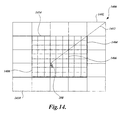
- FIGURE 14 For illustrative purposes, a representative section of computer display 1400 that contains a set of highly magnified pixels is depicted in FIGURE 14. More specifically, the sample section of computer display 1400 contains pixels 1402, 1404, 1406, 1408, 1410, a pointer 208, and a path 1412 that represents pointer 208 movement. As shown in FIGURE 14, a user employed input device, such as input device 110, is used to relocate the pointer 208 across pixels 1402, 1404, and1406. Pointer 208 movement across pixels 1404 and 1406 is not proportional to the input generated by the user because pixels 1404 and 1406 are part of a 3x3 pixel alignment area 1414.
- the pointer adjustment method 900 (FIGURE 9) and the calculation method 1000 (FIGURE 10) adjust movement of the pointer 208 to help users align GUI objects.
- the calculation method 1000 obtains directional friction curves that quantify resistance to pointer movement in each direction that the pointer 208 is projected to move.
- the pointer 208 is projected to move in both the horizontal (e.g. x-directional component) and vertical (e.g. y-directional component) directions.
- the directional friction curves obtained by the calculation method 1000 are linear because resistance to pointer movement in each component direction is constant.
- the path 1412 represents pointer 208 movement generated by a single pointer 208 movement event.
- the final location of the pointer 208 is inside the alignment area 1414.
- the area under the directional friction curves is larger than the projected movement of the pointer 208 in each component direction. In this situation, only a portion of the area under each directional friction curve is used to calculate an adjustment amount. Conversely, if the final location of the pointer 208 is outside the alignment area 1412, the total area under the directional friction curves would be used as the adjustment amounts.
Landscapes
- Engineering & Computer Science (AREA)
- Theoretical Computer Science (AREA)
- General Engineering & Computer Science (AREA)
- Human Computer Interaction (AREA)
- Physics & Mathematics (AREA)
- General Physics & Mathematics (AREA)
- User Interface Of Digital Computer (AREA)
- Position Input By Displaying (AREA)
Applications Claiming Priority (2)
| Application Number | Priority Date | Filing Date | Title |
|---|---|---|---|
| US828890 | 2004-04-21 | ||
| US10/828,890 US7293246B2 (en) | 2004-04-21 | 2004-04-21 | System and method for aligning objects using non-linear pointer movement |
Publications (2)
| Publication Number | Publication Date |
|---|---|
| EP1589409A2 true EP1589409A2 (de) | 2005-10-26 |
| EP1589409A3 EP1589409A3 (de) | 2012-02-29 |
Family
ID=34939404
Family Applications (1)
| Application Number | Title | Priority Date | Filing Date |
|---|---|---|---|
| EP05103171A Withdrawn EP1589409A3 (de) | 2004-04-21 | 2005-04-20 | System und Verfahren zum Ausrichten von Gegenständen unter Verwendung einer nicht-linearen Zeigerbewegung |
Country Status (5)
| Country | Link |
|---|---|
| US (1) | US7293246B2 (de) |
| EP (1) | EP1589409A3 (de) |
| JP (1) | JP4994604B2 (de) |
| KR (1) | KR100971853B1 (de) |
| CN (1) | CN100559336C (de) |
Cited By (1)
| Publication number | Priority date | Publication date | Assignee | Title |
|---|---|---|---|---|
| WO2014123756A1 (en) * | 2013-02-05 | 2014-08-14 | Nokia Corporation | Method and apparatus for a slider interface element |
Families Citing this family (14)
| Publication number | Priority date | Publication date | Assignee | Title |
|---|---|---|---|---|
| GB0222094D0 (en) * | 2002-09-24 | 2002-10-30 | Koninkl Philips Electronics Nv | Graphical user interface navigation method and apparatus |
| US7454707B2 (en) * | 2002-09-30 | 2008-11-18 | Canon Kabushiki Kaisha | Image editing method, image editing apparatus, program for implementing image editing method, and recording medium recording program |
| DE102005017850B4 (de) * | 2005-04-18 | 2014-08-21 | Siemens Aktiengesellschaft | Verfahren zur Integration vektorieller und/oder tensorieller Messdaten in eine Darstellung einer anatomischen Bildaufnahme |
| US7739611B2 (en) * | 2005-04-25 | 2010-06-15 | Aol Inc. | User interface with connectable elements |
| US9141402B2 (en) * | 2005-04-25 | 2015-09-22 | Aol Inc. | Providing a user interface |
| US20080256484A1 (en) * | 2007-04-12 | 2008-10-16 | Microsoft Corporation | Techniques for aligning and positioning objects |
| US20090207144A1 (en) * | 2008-01-07 | 2009-08-20 | Next Holdings Limited | Position Sensing System With Edge Positioning Enhancement |
| EP2235617A2 (de) | 2008-01-30 | 2010-10-06 | Thomson Licensing | Zeigersteuervorrichtung, verfahren dafür und zeigersteuerprogramm |
| JP4968321B2 (ja) * | 2009-12-25 | 2012-07-04 | 株式会社デンソー | 車両用操作入力装置 |
| JP2011210188A (ja) * | 2010-03-30 | 2011-10-20 | Sony Corp | 画像処理装置、画像表示方法、画像表示プログラム、および画像表示プログラムを記録した記録媒体 |
| EP2770413A3 (de) * | 2013-02-22 | 2017-01-04 | Samsung Electronics Co., Ltd. | Vorrichtung zur Bereitstellung eines Cursors in elektronischen Geräten und Verfahren dafür |
| JP5924554B2 (ja) * | 2014-01-06 | 2016-05-25 | コニカミノルタ株式会社 | オブジェクトの停止位置制御方法、操作表示装置およびプログラム |
| JP5924555B2 (ja) * | 2014-01-06 | 2016-05-25 | コニカミノルタ株式会社 | オブジェクトの停止位置制御方法、操作表示装置およびプログラム |
| US10331319B2 (en) | 2016-06-29 | 2019-06-25 | Adobe Inc. | Objects alignment and distribution layout |
Citations (1)
| Publication number | Priority date | Publication date | Assignee | Title |
|---|---|---|---|---|
| US5771042A (en) * | 1996-07-17 | 1998-06-23 | International Business Machines Corporation | Multi-size control for multiple adjacent workspaces |
Family Cites Families (31)
| Publication number | Priority date | Publication date | Assignee | Title |
|---|---|---|---|---|
| JPS61160793A (ja) * | 1985-01-10 | 1986-07-21 | 株式会社リコー | 情報処理装置 |
| US5123087A (en) * | 1990-04-27 | 1992-06-16 | Ashlar, Inc. | Geometric inference engine |
| US5164713A (en) * | 1991-10-15 | 1992-11-17 | Bain Lee L | Cursor position controller for use with mouse and display systems |
| WO1993022758A1 (en) * | 1992-05-07 | 1993-11-11 | Kensington Microware Limited | Method and apparatus for cursor positioning |
| US5508717A (en) * | 1992-07-28 | 1996-04-16 | Sony Corporation | Computer pointing device with dynamic sensitivity |
| JPH06175816A (ja) * | 1992-10-02 | 1994-06-24 | Internatl Business Mach Corp <Ibm> | コンピュータ・ディスプレイ上の入力装置ポインタ再トラッキング方法及び装置 |
| JPH06139022A (ja) * | 1992-10-30 | 1994-05-20 | Sharp Corp | 情報処理装置における座標入力システム |
| US5548707A (en) * | 1993-11-09 | 1996-08-20 | Adra Systems, Inc. | Method and system for design and drafting |
| CA2140164A1 (en) * | 1994-01-27 | 1995-07-28 | Kenneth R. Robertson | System and method for computer cursor control |
| US5815137A (en) * | 1994-10-19 | 1998-09-29 | Sun Microsystems, Inc. | High speed display system having cursor multiplexing scheme |
| TW288129B (de) * | 1995-04-28 | 1996-10-11 | Philips Electronics Nv | |
| US5732228A (en) * | 1995-11-14 | 1998-03-24 | International Business Machines Corporation | Method and system for per widget graphical pointer control within a data processing system graphical user interface |
| US6078308A (en) | 1995-12-13 | 2000-06-20 | Immersion Corporation | Graphical click surfaces for force feedback applications to provide user selection using cursor interaction with a trigger position within a boundary of a graphical object |
| US5774111A (en) * | 1996-02-12 | 1998-06-30 | Dassault Systemes | Method and apparatus for providing a dynamically oriented compass cursor on computer displays |
| US5880723A (en) * | 1996-04-30 | 1999-03-09 | Driskell; Stanley W. | Method to assess the physical effort to acquire physical targets |
| US6867790B1 (en) * | 1996-08-09 | 2005-03-15 | International Business Machines Corporation | Method and apparatus to conditionally constrain pointer movement on a computer display using visual cues, controlled pointer speed and barriers on the display which stop or restrict pointer movement |
| US5870079A (en) * | 1996-11-12 | 1999-02-09 | Legaltech, Inc. | Computer input device and controller therefor |
| US5786805A (en) * | 1996-12-27 | 1998-07-28 | Barry; Edwin Franklin | Method and apparatus for improving object selection on a computer display by providing cursor control with a sticky property |
| US5973670A (en) * | 1996-12-31 | 1999-10-26 | International Business Machines Corporation | Tactile feedback controller for computer cursor control device |
| JPH10198519A (ja) * | 1997-01-08 | 1998-07-31 | Toshiba Corp | ポインタ制御装置 |
| JPH1145156A (ja) * | 1997-07-25 | 1999-02-16 | Sharp Corp | 座標入力装置及び座標入力制御プログラムを記録したコンピュータ読み取り可能な記録媒体 |
| JPH1185402A (ja) * | 1997-09-10 | 1999-03-30 | Sharp Corp | ポインタ制御方法及び同方法に用いる記録媒体 |
| US6031531A (en) * | 1998-04-06 | 2000-02-29 | International Business Machines Corporation | Method and system in a graphical user interface for facilitating cursor object movement for physically challenged computer users |
| US6392675B1 (en) * | 1999-02-24 | 2002-05-21 | International Business Machines Corporation | Variable speed cursor movement |
| US7098933B1 (en) * | 1999-02-24 | 2006-08-29 | Autodesk, Inc. | Acquiring and unacquiring alignment and extension points |
| US6480813B1 (en) * | 1999-02-24 | 2002-11-12 | Autodesk, Inc. | Method and apparatus for defining a precision drawing in a drawing program |
| US6433775B1 (en) * | 1999-03-25 | 2002-08-13 | Monkeymedia, Inc. | Virtual force feedback interface |
| JP3477675B2 (ja) * | 1999-06-04 | 2003-12-10 | インターナショナル・ビジネス・マシーンズ・コーポレーション | ポインタ操作の補助方法 |
| ATE411275T1 (de) * | 2000-08-11 | 2008-10-15 | Japan Tobacco Inc | Calciumrezeptor-antagonisten |
| US6654003B2 (en) * | 2000-12-01 | 2003-11-25 | International Business Machines Corporation | Cursor control device |
| US6907581B2 (en) * | 2001-04-03 | 2005-06-14 | Ramot At Tel Aviv University Ltd. | Method and system for implicitly resolving pointing ambiguities in human-computer interaction (HCI) |
-
2004
- 2004-04-21 US US10/828,890 patent/US7293246B2/en not_active Expired - Fee Related
-
2005
- 2005-04-20 EP EP05103171A patent/EP1589409A3/de not_active Withdrawn
- 2005-04-20 CN CNB2005100837905A patent/CN100559336C/zh not_active Expired - Fee Related
- 2005-04-21 KR KR1020050033110A patent/KR100971853B1/ko not_active Expired - Fee Related
- 2005-04-21 JP JP2005123574A patent/JP4994604B2/ja not_active Expired - Fee Related
Patent Citations (1)
| Publication number | Priority date | Publication date | Assignee | Title |
|---|---|---|---|---|
| US5771042A (en) * | 1996-07-17 | 1998-06-23 | International Business Machines Corporation | Multi-size control for multiple adjacent workspaces |
Cited By (4)
| Publication number | Priority date | Publication date | Assignee | Title |
|---|---|---|---|---|
| WO2014123756A1 (en) * | 2013-02-05 | 2014-08-14 | Nokia Corporation | Method and apparatus for a slider interface element |
| US9652136B2 (en) | 2013-02-05 | 2017-05-16 | Nokia Technologies Oy | Method and apparatus for a slider interface element |
| US9747014B2 (en) | 2013-02-05 | 2017-08-29 | Nokia Technologies Oy | Method and apparatus for a slider interface element |
| US9760267B2 (en) | 2013-02-05 | 2017-09-12 | Nokia Technologies Oy | Method and apparatus for a slider interface element |
Also Published As
| Publication number | Publication date |
|---|---|
| CN1782965A (zh) | 2006-06-07 |
| KR20060047336A (ko) | 2006-05-18 |
| KR100971853B1 (ko) | 2010-07-22 |
| CN100559336C (zh) | 2009-11-11 |
| JP2005317003A (ja) | 2005-11-10 |
| EP1589409A3 (de) | 2012-02-29 |
| US7293246B2 (en) | 2007-11-06 |
| US20050240877A1 (en) | 2005-10-27 |
| JP4994604B2 (ja) | 2012-08-08 |
Similar Documents
| Publication | Publication Date | Title |
|---|---|---|
| US8248365B2 (en) | System and method for acquiring a target with intelligent pointer movement | |
| US7293246B2 (en) | System and method for aligning objects using non-linear pointer movement | |
| Guiard et al. | Object pointing: a complement to bitmap pointing in GUIs | |
| US6535233B1 (en) | Method and apparatus for adjusting the display scale of an image | |
| US6822662B1 (en) | User selected display of two-dimensional window in three dimensions on a computer screen | |
| US7460123B1 (en) | Dynamic control of graphic representations of data | |
| US5767850A (en) | Relocatable menu icon for accessing an application in a graphical user interface | |
| US5615347A (en) | Method and apparatus for linking images of sliders on a computer display | |
| EP0992878B1 (de) | Vorrichtung und Verfahren zur absoluten und relativen Bestimmung eines graphischen Positionsanzeigers | |
| TW442758B (en) | Digitizer with out-of-bounds tracking | |
| US6014127A (en) | Cursor positioning method | |
| JP2004078693A (ja) | 視野移動操作方法 | |
| JPH04276821A (ja) | コンピュータ表示制御システム | |
| US9772742B2 (en) | System and method for remote controlling computing device | |
| US20020067340A1 (en) | Method and apparatus for shorthand processing of medical images, wherein mouse positionings and/or actuations will immediately control image measuring functionalities, and a pertinent computer program | |
| US5526018A (en) | Stretching scales for computer documents or drawings | |
| US5995079A (en) | Method for controlling a variable of a dialog box with cursor movement | |
| US6664990B1 (en) | Computer display pointer with alternate hot spots | |
| JP2007536666A (ja) | ユーザと対話するためのグラフィック・ユーザ・インタフェース、システム、方法及びコンピュータプログラム | |
| EP2226707B1 (de) | Adaptives Zeigen - implizite Zuwachsanpassung für absolute Zeigevorrichtungen | |
| US20070198953A1 (en) | Target acquisition | |
| US7446751B2 (en) | Data input device, data input method, and data input program | |
| JPH01179193A (ja) | スクロール指示方式 | |
| JP2000020243A (ja) | カーソル制御方法、記憶媒体及び情報処理装置 | |
| US20030107567A1 (en) | Oriented three-dimensional editing glyphs |
Legal Events
| Date | Code | Title | Description |
|---|---|---|---|
| PUAI | Public reference made under article 153(3) epc to a published international application that has entered the european phase |
Free format text: ORIGINAL CODE: 0009012 |
|
| AK | Designated contracting states |
Kind code of ref document: A2 Designated state(s): AT BE BG CH CY CZ DE DK EE ES FI FR GB GR HU IE IS IT LI LT LU MC NL PL PT RO SE SI SK TR |
|
| AX | Request for extension of the european patent |
Extension state: AL BA HR LV MK YU |
|
| PUAL | Search report despatched |
Free format text: ORIGINAL CODE: 0009013 |
|
| AK | Designated contracting states |
Kind code of ref document: A3 Designated state(s): AT BE BG CH CY CZ DE DK EE ES FI FR GB GR HU IE IS IT LI LT LU MC NL PL PT RO SE SI SK TR |
|
| AX | Request for extension of the european patent |
Extension state: AL BA HR LV MK YU |
|
| RIC1 | Information provided on ipc code assigned before grant |
Ipc: G06F 3/033 20060101AFI20120124BHEP |
|
| 17P | Request for examination filed |
Effective date: 20120829 |
|
| AKX | Designation fees paid |
Designated state(s): AT BE BG CH CY CZ DE DK EE ES FI FR GB GR HU IE IS IT LI LT LU MC NL PL PT RO SE SI SK TR |
|
| 17Q | First examination report despatched |
Effective date: 20140204 |
|
| RAP1 | Party data changed (applicant data changed or rights of an application transferred) |
Owner name: MICROSOFT TECHNOLOGY LICENSING, LLC |
|
| STAA | Information on the status of an ep patent application or granted ep patent |
Free format text: STATUS: THE APPLICATION IS DEEMED TO BE WITHDRAWN |
|
| 18D | Application deemed to be withdrawn |
Effective date: 20160722 |