EP1589316A1 - Irreversible Temperaturfühler mit Schnappwirkung und Verwendung eines solchen Fühlers zum Entsichern eines Munitionskörpers - Google Patents
Irreversible Temperaturfühler mit Schnappwirkung und Verwendung eines solchen Fühlers zum Entsichern eines Munitionskörpers Download PDFInfo
- Publication number
- EP1589316A1 EP1589316A1 EP05102439A EP05102439A EP1589316A1 EP 1589316 A1 EP1589316 A1 EP 1589316A1 EP 05102439 A EP05102439 A EP 05102439A EP 05102439 A EP05102439 A EP 05102439A EP 1589316 A1 EP1589316 A1 EP 1589316A1
- Authority
- EP
- European Patent Office
- Prior art keywords
- detector
- pyrotechnic
- barrel
- initial position
- temperature
- Prior art date
- Legal status (The legal status is an assumption and is not a legal conclusion. Google has not performed a legal analysis and makes no representation as to the accuracy of the status listed.)
- Withdrawn
Links
- 230000009471 action Effects 0.000 title claims description 23
- 230000002427 irreversible effect Effects 0.000 title claims description 5
- 239000000463 material Substances 0.000 claims abstract description 56
- 230000000717 retained effect Effects 0.000 claims abstract description 5
- 230000006835 compression Effects 0.000 claims abstract description 4
- 238000007906 compression Methods 0.000 claims abstract description 4
- 230000007246 mechanism Effects 0.000 claims description 57
- 239000002360 explosive Substances 0.000 claims description 11
- 230000004913 activation Effects 0.000 claims description 10
- 230000000694 effects Effects 0.000 claims description 10
- 238000010304 firing Methods 0.000 claims description 8
- 239000000203 mixture Substances 0.000 claims description 4
- 239000003832 thermite Substances 0.000 claims description 3
- 238000005202 decontamination Methods 0.000 claims description 2
- 230000003588 decontaminative effect Effects 0.000 claims description 2
- 230000002401 inhibitory effect Effects 0.000 claims 1
- 230000005764 inhibitory process Effects 0.000 description 7
- 238000001514 detection method Methods 0.000 description 5
- 230000008901 benefit Effects 0.000 description 4
- 230000005496 eutectics Effects 0.000 description 3
- 238000004880 explosion Methods 0.000 description 3
- 239000007788 liquid Substances 0.000 description 3
- 239000007787 solid Substances 0.000 description 3
- 230000007704 transition Effects 0.000 description 3
- XTFIVUDBNACUBN-UHFFFAOYSA-N 1,3,5-trinitro-1,3,5-triazinane Chemical compound [O-][N+](=O)N1CN([N+]([O-])=O)CN([N+]([O-])=O)C1 XTFIVUDBNACUBN-UHFFFAOYSA-N 0.000 description 2
- YSIBQULRFXITSW-OWOJBTEDSA-N 1,3,5-trinitro-2-[(e)-2-(2,4,6-trinitrophenyl)ethenyl]benzene Chemical compound [O-][N+](=O)C1=CC([N+](=O)[O-])=CC([N+]([O-])=O)=C1\C=C\C1=C([N+]([O-])=O)C=C([N+]([O-])=O)C=C1[N+]([O-])=O YSIBQULRFXITSW-OWOJBTEDSA-N 0.000 description 2
- 230000008859 change Effects 0.000 description 2
- 230000000295 complement effect Effects 0.000 description 2
- 230000035939 shock Effects 0.000 description 2
- 230000003213 activating effect Effects 0.000 description 1
- 239000000956 alloy Substances 0.000 description 1
- 229910045601 alloy Inorganic materials 0.000 description 1
- 230000004888 barrier function Effects 0.000 description 1
- 230000005540 biological transmission Effects 0.000 description 1
- 239000002775 capsule Substances 0.000 description 1
- 238000005474 detonation Methods 0.000 description 1
- 239000000446 fuel Substances 0.000 description 1
- 238000010438 heat treatment Methods 0.000 description 1
- 239000003999 initiator Substances 0.000 description 1
- 230000003993 interaction Effects 0.000 description 1
- 238000012423 maintenance Methods 0.000 description 1
- 230000008018 melting Effects 0.000 description 1
- 238000002844 melting Methods 0.000 description 1
- 238000009527 percussion Methods 0.000 description 1
- 239000003380 propellant Substances 0.000 description 1
- 239000000523 sample Substances 0.000 description 1
- 229910052709 silver Inorganic materials 0.000 description 1
- 239000004332 silver Substances 0.000 description 1
Images


Classifications
-
- F—MECHANICAL ENGINEERING; LIGHTING; HEATING; WEAPONS; BLASTING
- F42—AMMUNITION; BLASTING
- F42C—AMMUNITION FUZES; ARMING OR SAFETY MEANS THEREFOR
- F42C15/00—Arming-means in fuzes; Safety means for preventing premature detonation of fuzes or charges
- F42C15/36—Arming-means in fuzes; Safety means for preventing premature detonation of fuzes or charges wherein arming is effected by combustion or fusion of an element; Arming methods using temperature gradients
Definitions
- the present invention relates to a temperature detector to sudden and irreversible action. It applies in particular to a device for deconfinement to avoid the explosion of a charge confined in an enclosure (thruster or explosive charge of a munition) in the presence fire.
- deconfusion devices In order to limit the level of reaction of ammunition, and therefore the associated hazard, deconfusion devices are used.
- the decontamination of ammunition thus makes it possible to protect individuals and goods in the vicinity of an ammunition storage airborne, naval), to protect the premises itself, and to avoid in chains.
- a deconfining device generally includes a temperature detector, this detector being of mechanical type or electronic.
- the detector allows when the surrounding temperature exceeds a certain threshold to open the enclosure in which is confined a explosive charge.
- the opening of the enclosure avoids the explosion of the charge by allowing it to ignite before any pressure buildup.
- the firing of a charge is indeed a lower risk compared to its explosion, because the fire can be controlled by specialized teams to land or at sea in the fight against fire.
- the known deconfining devices use a Autonomous power source (electric) to detect temperature surrounding.
- Ammunition can be stored for long periods of time periods of the order of several decades. This poses a problem because the sources of energy are not reliable over such long periods.
- An object of the invention is to obtain a detector that can be used in a deconfinement device and having reliable operation on a long period of time.
- Such a detector can be used more generally for trigger from a given temperature an instant action and irreversible to treat an accidental event.
- the detector using no energy source other than the prestressing of a mechanical part its operation is reliable on a long period of time. It also has the advantage of being simple to implement and economic.
- the operation of the detector can be made more reliable by detecting two levels of different temperatures.
- the sudden action of the detector is the activation of a pyrotechnic charge.
- the pyrotechnic charge can be a detonator or an igniter.
- the second mechanism includes a striker configured to activate the pyrotechnic charge when the release of the second mechanism if the first mechanism has been released.
- the detector comprises in addition a barrel arranged in a first position when the first mechanism is in its initial position, the barrel being configured to prevent the firing pin from activating the pyrotechnic charge when the barrel is in its first position, the barrel being articulated in rotation to be in a second position when the first mechanism is released, the barrel being configured to allow the firing pin to activate the load pyrotechnic when the barrel is in its second position.
- the first mechanism includes a lock arranged to hold the barrel in its first position as long as the first mechanism is in its initial position, the barrel being prestressed in its first position so as to turn towards its second position under the effect of said prestressing when the first mechanism is released.
- the invention also relates to a deconfinement device pyrotechnic device comprising at least one detector whose sudden action is the activation of a detonator, and a pyrotechnic cutting chain, in which the detector is arranged so that activation of the detonator initiates the pyrotechnic cutting chain.
- the cutting line pyrotechnic is a chopper cord, a pyrotechnic hammer or a thermite type composition.
- the invention applies to a system comprising a device for deconfinement, an enclosure and an explosive charge placed in the enclosure, the cutting chain being arranged to weaken or cut the enclosure.
- the system comprises in addition an inhibition device presenting a command, the command being able to receive an external command, the muting device being configured to neutralize the deconfinement device when an external order is received by the order
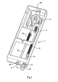
- FIGS. 1 and 2a which is represented an example embodiment of a temperature detector according to the invention.
- the detection of the temperature is carried out by means of at least a material sensitive to temperature, responding to a temperature determined.
- This material can for example change state or shape to this determined temperature.
- the material used may be a eutectic material, ie a material that passes directly from the state solid in the liquid state. This avoids the use of temperature probes or electronic detection system that require electrical energy stored.
- the detector thus comprises a first material sensitive to temperature.
- the first material 10 has, for example, a shape substantially cylindrical.
- the first material 10 is retained in a support 11 secured to the housing 2 of the detector 1.
- the support is external to the housing and has openings. This arrangement external allows the material 10 to be in direct contact with the temperature external.
- the support comprises disks 11a traversed by the first material 10, these discs being interconnected by wings 11b.
- the material 10 is also attached to a cylindrical rod 12.
- the rod In the initial position (called still rest position), shown in Figure 1, the rod is prestressed by a spring 13 tending to push the rod 12 against the material 10.
- the support 11 holds the material 10 which works in compression.
- the temperature of the material 10 reaches a determined value ⁇ 1, it passes from the solid state to the liquid state without transition (melting) under the effect of heat. The material then flows and releases the rod 12.
- the rod 12 then moves under the effect of the spring 13 towards the outside of the housing.
- FIGS. 1 and 2a illustrate a particular embodiment of the detector according to the invention which constitutes a preferred embodiment. Indeed as has been said previously, this embodiment several advantages.
- the material 10 because of the positioning of the material 10 on the outside housing and the structure of the support 11, it allows the material 10 to be in direct contact with the ambient temperature.
- the structure of the support 11 allows an evacuation fast and complete material 10 when the latter undergoes a deformation of makes heat. This last advantage being particularly obtained in the case of a eutectic material.
- the detector according to the invention may nevertheless have features of structures different from those illustrated in FIGS. 2a.
- the detector components may have different forms.
- the support 11 can be replaced by a tubular shaped support perforated with multiple through holes, wherein the material 10 is held in position (tight), in direct contact with the external temperature.
- an alloy can be used shape memory that fades at a specific temperature.
- a gas can be enclosed in an aneroid capsule (such as in altimeters), the expansion of the gas causing a movement translation of a rod.
- the detector components can be arranged differently.
- the support 11 can be placed inside the housing instead of being external. The material 10 will then be in contact with the internal temperature of the housing.
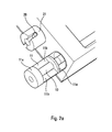
- the detector can further include a second temperature sensitive material.
- the second material 20 has a substantially cylindrical shape. This material 20 forms a calibrated pin working in shear, the pin being retained by a support 21 secured to the housing 2. In this mode of realization, the support 21 and the pin 21 are placed outside the housing, which allows the material forming the pin 21 to be in direct contact with the external temperature.
- the components of the detector may have a different shape or be arranged differently, as shown in particular in Figure 2b.
- the pin passes through a cylindrical rod 22.
- the rod 22 When the rod 22 is in its initial position (or rest position), it is prestressed by a spring 23 tending to move the rod to the inside of the housing.
- the two mechanisms are arranged to produce the abrupt action of the detector only when they are both released.
- the abrupt action of the detector can be an activation of a pyrotechnic charge.
- Load pyrotechnic may be a detonator or an igniter. This allows quickly dispose of significant energy from an energy medium or weak mechanics (prestressed springs).
- the detector can be used in applications (military or civilian) where it is necessary to have a significant energy when the temperature reaches a certain threshold.
- a detector according to this last embodiment advantageous can be useful to activate a hydraulic valve or another mechanism requiring significant energy. It will be understood that advantageous embodiments previously described (detection of two independent events and activation of a pyrotechnic charge) are independent and can be implemented separately.
- the second mechanism When the abrupt action of the detector is the activation of a detonator, the second mechanism, released second, is the one that activates the detonator.
- the first mechanism inhibits or allows activation of the detonator by the second mechanism.
- the second mechanism includes a striker configured to activate the pyrotechnic charge when the release of the second mechanism if the first mechanism has been released.
- the striker is formed by the rod 22, a tip end is intended to hit the load pyrotechnic when the pin 20 releases the second mechanism. However, if the first mechanism was not released, it impedes the percussion of the tip the pyrotechnic charge.
- the first mechanism can to align a pyrotechnic chain when it is released, this chain pyrotechnic can then be activated by the second mechanism.
- the first mechanism can act in translation (sliding drawer) to cause the alignment, the pyrotechnic chain being misaligned when the first mechanism is in its initial position.
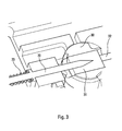
- the first position of the cylinder is shown in Figure 4.
- the barrel is in this first position when the first mechanism is in its initial position. In this first position, the barrel prevents the striker 22 to activate the pyrotechnic charge.
- the second position of the cylinder is shown in FIG. barrel is in this second position when the first mechanism is released. In this second position, the barrel allows the firing pin 22 to activate the pyrotechnic charge.
- the pyrotechnic charge 31 forms the first element (initiator) of a pyrotechnic chain 31, 32.
- the load 31 can be placed in the barrel itself, as shown in Figure 3. According to another mode of realization (not shown), the load is placed outside the barrel, the barrel being placed between the firing pin and the load, the barrel having a opening allowing the firing pin to reach the load when the barrel is in the second position.
- the passage of the barrel from the first to the second position allows to align the striker with the load 31.
- the inhibition of the striker's action is caused by the misalignment of an element of the pyrotechnic chain 31, 32.
- the misalignment is produced by the barrel when it is in the first position.
- the rotation of the barrel is actuated by the first mechanism.
- the barrel is held in its first position by a latch 14, the barrel being prestressed in its first position so as to turn towards its second position under the effect of said prestressing when the lock is erased.
- the lock is an integral part of the first mechanism, so that fade when the first mechanism is released.
- the latch 14 is placed at one end of the rod 12.
- the deconfinement device comprises a pyrotechnic cutting chain 41 pressed against the wall an enclosure 40.
- the enclosure contains an explosive charge 43.
- detector whose action is the activation of a detonator 31.
- the detonator 31 is arranged to initiate the pyrotechnic cutting chain.
- the chain of cut 41 as for it is arranged to weaken or cut the enclosure 40.
- a pyrotechnic transmission line 42 so as to transmit the action of the detector at the cutting line.
- a chopper cord is a charge linear with dihedral effect (same effect as hollow charges).
- the cord chopper comprises an envelope 50 made of material to be sprayed.
- the envelope contains an explosive 51.
- Hexogen known under the acronym RDX in the Anglo-Saxon literature
- HNS hexa-nitro-stilbene
- the whole of the envelope 50 and the explosive 51 can itself be contained in a thermal protection device or more simply in a maintenance mechanics.
- FIG. 9a which shows a mode of alternative embodiment of a pyrotechnic cutting line.
- the chain of cutout shown in this figure is of the pyrotechnic hammer type.
- a pyrotechnic hammer comprises a chamber 52 that can also provide thermal protection.
- the enclosure has substantially a shape U shaped, forming a cavity in which is placed an explosive 53.
- the enclosure contains a blade 54 for closing the cavity.
- the blade 54 is disposed facing the enclosure 40 to be cut, with care an empty space 55 between the blade 54 and the enclosure 40.
- the detonation of the explosive 53 projects the blade.
- the impact of the blade generates a shock wave on the structure of the enclosure to be cut.
- the shock is capable of generating a crack that will spread.
- a device of inhibition to the deconfinement device, to inhibit the system when firing the missile.
- the free flight temperatures of the missile kinetic heating of about 500 ° C
- the inhibition can be achieved by a drawer 60 making part of the detector.
- the action of the multi-level detector can be inhibited.
- electromechanical actuators 62 allowing to block the movement of the barrel by engaging a lug.
- the inhibition device presents a command, the command being able to receive an external order.
- the muting device is configured to neutralize the deconfinement device when an external order is received by the order.
- the inhibition device integral part of the detector and directly inhibits the action of the detector.
Landscapes
- Engineering & Computer Science (AREA)
- General Engineering & Computer Science (AREA)
- Measuring Temperature Or Quantity Of Heat (AREA)
- Testing Or Calibration Of Command Recording Devices (AREA)
Applications Claiming Priority (2)
| Application Number | Priority Date | Filing Date | Title |
|---|---|---|---|
| FR0404142 | 2004-04-20 | ||
| FR0404142A FR2869102A1 (fr) | 2004-04-20 | 2004-04-20 | Detecteur de temperature a action brusque et irreversible et application a un dispositif de deconfinement de munitions |
Publications (1)
| Publication Number | Publication Date |
|---|---|
| EP1589316A1 true EP1589316A1 (de) | 2005-10-26 |
Family
ID=34939077
Family Applications (1)
| Application Number | Title | Priority Date | Filing Date |
|---|---|---|---|
| EP05102439A Withdrawn EP1589316A1 (de) | 2004-04-20 | 2005-03-25 | Irreversible Temperaturfühler mit Schnappwirkung und Verwendung eines solchen Fühlers zum Entsichern eines Munitionskörpers |
Country Status (2)
| Country | Link |
|---|---|
| EP (1) | EP1589316A1 (de) |
| FR (1) | FR2869102A1 (de) |
Cited By (1)
| Publication number | Priority date | Publication date | Assignee | Title |
|---|---|---|---|---|
| CN115060124A (zh) * | 2022-07-08 | 2022-09-16 | 江西洪都航空工业集团有限责任公司 | 一种通用性便携式导弹弹翼锁紧装置 |
Citations (9)
| Publication number | Priority date | Publication date | Assignee | Title |
|---|---|---|---|---|
| US4577544A (en) * | 1984-05-14 | 1986-03-25 | Ici Americas Inc. | Ultrafast thermal actuator |
| US4597261A (en) * | 1984-05-25 | 1986-07-01 | Hughes Aircraft Company | Thermally actuated rocket motor safety system |
| US4843965A (en) * | 1988-02-23 | 1989-07-04 | The United States Of America As Represented By The Secretary Of The Navy | Thermally activated triggering device |
| EP0343615A1 (de) * | 1988-05-27 | 1989-11-29 | Streif, Hans | Gasanschlussarmatur |
| US4961313A (en) * | 1988-08-08 | 1990-10-09 | Hughes Aircraft Company | Thermally initiated mechanically fired device for providing protection against slow cook-off |
| FR2685079A1 (fr) * | 1991-12-13 | 1993-06-18 | Lacroix E Tous Artifices | Dispositif mecanique sensible a la temperature pour l'initiation d'un systeme pyrotechnique. |
| US5275194A (en) * | 1992-11-30 | 1994-01-04 | Donald E. Oates | Fire control valve with replaceable locking pin assembly |
| FR2699664A1 (fr) * | 1992-12-23 | 1994-06-24 | Lacroix E Tous Artifices | Perfectionnement aux dispositifs pyrotechniques thermosensibles. |
| US5445077A (en) * | 1992-12-18 | 1995-08-29 | Giat Industries | Initiation device for a pyrotechnic system |
-
2004
- 2004-04-20 FR FR0404142A patent/FR2869102A1/fr not_active Withdrawn
-
2005
- 2005-03-25 EP EP05102439A patent/EP1589316A1/de not_active Withdrawn
Patent Citations (9)
| Publication number | Priority date | Publication date | Assignee | Title |
|---|---|---|---|---|
| US4577544A (en) * | 1984-05-14 | 1986-03-25 | Ici Americas Inc. | Ultrafast thermal actuator |
| US4597261A (en) * | 1984-05-25 | 1986-07-01 | Hughes Aircraft Company | Thermally actuated rocket motor safety system |
| US4843965A (en) * | 1988-02-23 | 1989-07-04 | The United States Of America As Represented By The Secretary Of The Navy | Thermally activated triggering device |
| EP0343615A1 (de) * | 1988-05-27 | 1989-11-29 | Streif, Hans | Gasanschlussarmatur |
| US4961313A (en) * | 1988-08-08 | 1990-10-09 | Hughes Aircraft Company | Thermally initiated mechanically fired device for providing protection against slow cook-off |
| FR2685079A1 (fr) * | 1991-12-13 | 1993-06-18 | Lacroix E Tous Artifices | Dispositif mecanique sensible a la temperature pour l'initiation d'un systeme pyrotechnique. |
| US5275194A (en) * | 1992-11-30 | 1994-01-04 | Donald E. Oates | Fire control valve with replaceable locking pin assembly |
| US5445077A (en) * | 1992-12-18 | 1995-08-29 | Giat Industries | Initiation device for a pyrotechnic system |
| FR2699664A1 (fr) * | 1992-12-23 | 1994-06-24 | Lacroix E Tous Artifices | Perfectionnement aux dispositifs pyrotechniques thermosensibles. |
Cited By (2)
| Publication number | Priority date | Publication date | Assignee | Title |
|---|---|---|---|---|
| CN115060124A (zh) * | 2022-07-08 | 2022-09-16 | 江西洪都航空工业集团有限责任公司 | 一种通用性便携式导弹弹翼锁紧装置 |
| CN115060124B (zh) * | 2022-07-08 | 2023-11-03 | 江西洪都航空工业集团有限责任公司 | 一种通用性便携式导弹弹翼锁紧装置 |
Also Published As
| Publication number | Publication date |
|---|---|
| FR2869102A1 (fr) | 2005-10-21 |
Similar Documents
| Publication | Publication Date | Title |
|---|---|---|
| EP0048204B1 (de) | Patrone mit pyrotechnisch betätigter Nutzladung und mit Sicherheitseinrichtungen | |
| CA2744543A1 (fr) | Verin a course declenchee pour dispositif de securite integre a un vehicule automobile, pour la protection d'un pieton en cas de choc frontal | |
| FR2564965A1 (fr) | Dispositif d'interruption de chaine pyrotechnique sensible a la temperature | |
| WO1994015168A1 (fr) | Dispositif d'initiation pour un systeme pyrotechnique | |
| EP0573328B1 (de) | Selbstzerlegungssystem für Submunition mittels chemischer Ätzung | |
| EP0545764B1 (de) | Verriegelungsvorrichtung einer Hülse die pyrotechnische Materialien enthält | |
| FR3040702A1 (fr) | Systeme et procede de fracturation d'un materiau solide | |
| EP1589316A1 (de) | Irreversible Temperaturfühler mit Schnappwirkung und Verwendung eines solchen Fühlers zum Entsichern eines Munitionskörpers | |
| FR2504254A1 (fr) | Mine antichar perfectionnee | |
| WO2002003014A1 (fr) | Projectile pour le declenchement d'avalanches | |
| EP2029956B1 (de) | Sicherheitszünder für pyrotechnische vorrichtung | |
| FR2563622A1 (fr) | Dispositif de securite et d'armement pour engins explosifs | |
| EP0559520B1 (de) | Barometrisches Sicherheitsventil und einer eine ähnliche pyrotechnische Vorrichtung enthaltender Gegenstand | |
| FR2699660A1 (fr) | Système d'amorçage et d'auto-destruction d'une munition, en particulier d'une sous-munition destinée à être éjectée d'un obus cargo avec un mouvement de rotation propre autour d'un axe. | |
| FR2551198A1 (fr) | Dispositif de neutralisation des allumeurs de mine | |
| EP4176225B1 (de) | Zünder mit selbstzerstörungsvorrichtung für ein kreiselgeschoss | |
| EP2769168B1 (de) | Gasgenerator mit einer sicherheitsvorrichtung für langsame erhitzung | |
| EP0207822B1 (de) | Sicherheitsvorrichtung für von Rohren abgeschossenen explosiven Flugkörper | |
| FR2691795A1 (fr) | Système d'auto-destruction d'une munition, en particulier d'une sous-munition d'obus cargo comprenant un générateur de chaleur. | |
| FR2736973A1 (fr) | Activateur mecanique mu par un generateur de gaz pyrotechnique | |
| FR2691796A1 (fr) | Système d'auto-destruction d'une munition en particulier d'une sous-munition d'obus cargo comprenant un générateur de gaz. | |
| FR2726359A1 (fr) | Fusee d'impact a double securite | |
| FR2699664A1 (fr) | Perfectionnement aux dispositifs pyrotechniques thermosensibles. | |
| FR2691798A1 (fr) | Système d'auto-destruction d'une munition, en particulier d'une sous-munition d'obus cargo par attaque chimique. | |
| FR2669106A1 (fr) | Bouchon allumeur de grenade a main polyvalent, a securite de lancement et a fonctions percutante et fusante. |
Legal Events
| Date | Code | Title | Description |
|---|---|---|---|
| PUAI | Public reference made under article 153(3) epc to a published international application that has entered the european phase |
Free format text: ORIGINAL CODE: 0009012 |
|
| AK | Designated contracting states |
Kind code of ref document: A1 Designated state(s): AT BE BG CH CY CZ DE DK EE ES FI FR GB GR HU IE IS IT LI LT LU MC NL PL PT RO SE SI SK TR |
|
| AX | Request for extension of the european patent |
Extension state: AL BA HR LV MK YU |
|
| 17P | Request for examination filed |
Effective date: 20060116 |
|
| AKX | Designation fees paid |
Designated state(s): AT BE BG CH CY CZ DE DK EE ES FI FR GB GR HU IE IS IT LI LT LU MC NL PL PT RO SE SI SK TR |
|
| STAA | Information on the status of an ep patent application or granted ep patent |
Free format text: STATUS: THE APPLICATION IS DEEMED TO BE WITHDRAWN |
|
| 18D | Application deemed to be withdrawn |
Effective date: 20061114 |