EP1589316A1 - Irreversible snap action temperature detector and application of such a detector and use of such a detector for the deconfinement of ammunition - Google Patents
Irreversible snap action temperature detector and application of such a detector and use of such a detector for the deconfinement of ammunition Download PDFInfo
- Publication number
- EP1589316A1 EP1589316A1 EP05102439A EP05102439A EP1589316A1 EP 1589316 A1 EP1589316 A1 EP 1589316A1 EP 05102439 A EP05102439 A EP 05102439A EP 05102439 A EP05102439 A EP 05102439A EP 1589316 A1 EP1589316 A1 EP 1589316A1
- Authority
- EP
- European Patent Office
- Prior art keywords
- detector
- pyrotechnic
- barrel
- initial position
- temperature
- Prior art date
- Legal status (The legal status is an assumption and is not a legal conclusion. Google has not performed a legal analysis and makes no representation as to the accuracy of the status listed.)
- Withdrawn
Links
Images


Classifications
-
- F—MECHANICAL ENGINEERING; LIGHTING; HEATING; WEAPONS; BLASTING
- F42—AMMUNITION; BLASTING
- F42C—AMMUNITION FUZES; ARMING OR SAFETY MEANS THEREFOR
- F42C15/00—Arming-means in fuzes; Safety means for preventing premature detonation of fuzes or charges
- F42C15/36—Arming-means in fuzes; Safety means for preventing premature detonation of fuzes or charges wherein arming is effected by combustion or fusion of an element; Arming methods using temperature gradients
Definitions
- the present invention relates to a temperature detector to sudden and irreversible action. It applies in particular to a device for deconfinement to avoid the explosion of a charge confined in an enclosure (thruster or explosive charge of a munition) in the presence fire.
- deconfusion devices In order to limit the level of reaction of ammunition, and therefore the associated hazard, deconfusion devices are used.
- the decontamination of ammunition thus makes it possible to protect individuals and goods in the vicinity of an ammunition storage airborne, naval), to protect the premises itself, and to avoid in chains.
- a deconfining device generally includes a temperature detector, this detector being of mechanical type or electronic.
- the detector allows when the surrounding temperature exceeds a certain threshold to open the enclosure in which is confined a explosive charge.
- the opening of the enclosure avoids the explosion of the charge by allowing it to ignite before any pressure buildup.
- the firing of a charge is indeed a lower risk compared to its explosion, because the fire can be controlled by specialized teams to land or at sea in the fight against fire.
- the known deconfining devices use a Autonomous power source (electric) to detect temperature surrounding.
- Ammunition can be stored for long periods of time periods of the order of several decades. This poses a problem because the sources of energy are not reliable over such long periods.
- An object of the invention is to obtain a detector that can be used in a deconfinement device and having reliable operation on a long period of time.
- Such a detector can be used more generally for trigger from a given temperature an instant action and irreversible to treat an accidental event.
- the detector using no energy source other than the prestressing of a mechanical part its operation is reliable on a long period of time. It also has the advantage of being simple to implement and economic.
- the operation of the detector can be made more reliable by detecting two levels of different temperatures.
- the sudden action of the detector is the activation of a pyrotechnic charge.
- the pyrotechnic charge can be a detonator or an igniter.
- the second mechanism includes a striker configured to activate the pyrotechnic charge when the release of the second mechanism if the first mechanism has been released.
- the detector comprises in addition a barrel arranged in a first position when the first mechanism is in its initial position, the barrel being configured to prevent the firing pin from activating the pyrotechnic charge when the barrel is in its first position, the barrel being articulated in rotation to be in a second position when the first mechanism is released, the barrel being configured to allow the firing pin to activate the load pyrotechnic when the barrel is in its second position.
- the first mechanism includes a lock arranged to hold the barrel in its first position as long as the first mechanism is in its initial position, the barrel being prestressed in its first position so as to turn towards its second position under the effect of said prestressing when the first mechanism is released.
- the invention also relates to a deconfinement device pyrotechnic device comprising at least one detector whose sudden action is the activation of a detonator, and a pyrotechnic cutting chain, in which the detector is arranged so that activation of the detonator initiates the pyrotechnic cutting chain.
- the cutting line pyrotechnic is a chopper cord, a pyrotechnic hammer or a thermite type composition.
- the invention applies to a system comprising a device for deconfinement, an enclosure and an explosive charge placed in the enclosure, the cutting chain being arranged to weaken or cut the enclosure.
- the system comprises in addition an inhibition device presenting a command, the command being able to receive an external command, the muting device being configured to neutralize the deconfinement device when an external order is received by the order
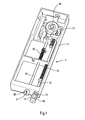
- FIGS. 1 and 2a which is represented an example embodiment of a temperature detector according to the invention.
- the detection of the temperature is carried out by means of at least a material sensitive to temperature, responding to a temperature determined.
- This material can for example change state or shape to this determined temperature.
- the material used may be a eutectic material, ie a material that passes directly from the state solid in the liquid state. This avoids the use of temperature probes or electronic detection system that require electrical energy stored.
- the detector thus comprises a first material sensitive to temperature.
- the first material 10 has, for example, a shape substantially cylindrical.
- the first material 10 is retained in a support 11 secured to the housing 2 of the detector 1.
- the support is external to the housing and has openings. This arrangement external allows the material 10 to be in direct contact with the temperature external.
- the support comprises disks 11a traversed by the first material 10, these discs being interconnected by wings 11b.
- the material 10 is also attached to a cylindrical rod 12.
- the rod In the initial position (called still rest position), shown in Figure 1, the rod is prestressed by a spring 13 tending to push the rod 12 against the material 10.
- the support 11 holds the material 10 which works in compression.
- the temperature of the material 10 reaches a determined value ⁇ 1, it passes from the solid state to the liquid state without transition (melting) under the effect of heat. The material then flows and releases the rod 12.
- the rod 12 then moves under the effect of the spring 13 towards the outside of the housing.
- FIGS. 1 and 2a illustrate a particular embodiment of the detector according to the invention which constitutes a preferred embodiment. Indeed as has been said previously, this embodiment several advantages.
- the material 10 because of the positioning of the material 10 on the outside housing and the structure of the support 11, it allows the material 10 to be in direct contact with the ambient temperature.
- the structure of the support 11 allows an evacuation fast and complete material 10 when the latter undergoes a deformation of makes heat. This last advantage being particularly obtained in the case of a eutectic material.
- the detector according to the invention may nevertheless have features of structures different from those illustrated in FIGS. 2a.
- the detector components may have different forms.
- the support 11 can be replaced by a tubular shaped support perforated with multiple through holes, wherein the material 10 is held in position (tight), in direct contact with the external temperature.
- an alloy can be used shape memory that fades at a specific temperature.
- a gas can be enclosed in an aneroid capsule (such as in altimeters), the expansion of the gas causing a movement translation of a rod.
- the detector components can be arranged differently.
- the support 11 can be placed inside the housing instead of being external. The material 10 will then be in contact with the internal temperature of the housing.
- the detector can further include a second temperature sensitive material.
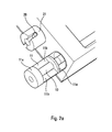
- the second material 20 has a substantially cylindrical shape. This material 20 forms a calibrated pin working in shear, the pin being retained by a support 21 secured to the housing 2. In this mode of realization, the support 21 and the pin 21 are placed outside the housing, which allows the material forming the pin 21 to be in direct contact with the external temperature.
- the components of the detector may have a different shape or be arranged differently, as shown in particular in Figure 2b.
- the pin passes through a cylindrical rod 22.
- the rod 22 When the rod 22 is in its initial position (or rest position), it is prestressed by a spring 23 tending to move the rod to the inside of the housing.
- the two mechanisms are arranged to produce the abrupt action of the detector only when they are both released.
- the abrupt action of the detector can be an activation of a pyrotechnic charge.
- Load pyrotechnic may be a detonator or an igniter. This allows quickly dispose of significant energy from an energy medium or weak mechanics (prestressed springs).
- the detector can be used in applications (military or civilian) where it is necessary to have a significant energy when the temperature reaches a certain threshold.
- a detector according to this last embodiment advantageous can be useful to activate a hydraulic valve or another mechanism requiring significant energy. It will be understood that advantageous embodiments previously described (detection of two independent events and activation of a pyrotechnic charge) are independent and can be implemented separately.
- the second mechanism When the abrupt action of the detector is the activation of a detonator, the second mechanism, released second, is the one that activates the detonator.
- the first mechanism inhibits or allows activation of the detonator by the second mechanism.
- the second mechanism includes a striker configured to activate the pyrotechnic charge when the release of the second mechanism if the first mechanism has been released.
- the striker is formed by the rod 22, a tip end is intended to hit the load pyrotechnic when the pin 20 releases the second mechanism. However, if the first mechanism was not released, it impedes the percussion of the tip the pyrotechnic charge.
- the first mechanism can to align a pyrotechnic chain when it is released, this chain pyrotechnic can then be activated by the second mechanism.
- the first mechanism can act in translation (sliding drawer) to cause the alignment, the pyrotechnic chain being misaligned when the first mechanism is in its initial position.
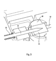
- the first position of the cylinder is shown in Figure 4.
- the barrel is in this first position when the first mechanism is in its initial position. In this first position, the barrel prevents the striker 22 to activate the pyrotechnic charge.
- the second position of the cylinder is shown in FIG. barrel is in this second position when the first mechanism is released. In this second position, the barrel allows the firing pin 22 to activate the pyrotechnic charge.
- the pyrotechnic charge 31 forms the first element (initiator) of a pyrotechnic chain 31, 32.
- the load 31 can be placed in the barrel itself, as shown in Figure 3. According to another mode of realization (not shown), the load is placed outside the barrel, the barrel being placed between the firing pin and the load, the barrel having a opening allowing the firing pin to reach the load when the barrel is in the second position.
- the passage of the barrel from the first to the second position allows to align the striker with the load 31.
- the inhibition of the striker's action is caused by the misalignment of an element of the pyrotechnic chain 31, 32.
- the misalignment is produced by the barrel when it is in the first position.
- the rotation of the barrel is actuated by the first mechanism.
- the barrel is held in its first position by a latch 14, the barrel being prestressed in its first position so as to turn towards its second position under the effect of said prestressing when the lock is erased.
- the lock is an integral part of the first mechanism, so that fade when the first mechanism is released.
- the latch 14 is placed at one end of the rod 12.
- the deconfinement device comprises a pyrotechnic cutting chain 41 pressed against the wall an enclosure 40.
- the enclosure contains an explosive charge 43.
- detector whose action is the activation of a detonator 31.
- the detonator 31 is arranged to initiate the pyrotechnic cutting chain.
- the chain of cut 41 as for it is arranged to weaken or cut the enclosure 40.
- a pyrotechnic transmission line 42 so as to transmit the action of the detector at the cutting line.
- a chopper cord is a charge linear with dihedral effect (same effect as hollow charges).
- the cord chopper comprises an envelope 50 made of material to be sprayed.
- the envelope contains an explosive 51.
- Hexogen known under the acronym RDX in the Anglo-Saxon literature
- HNS hexa-nitro-stilbene
- the whole of the envelope 50 and the explosive 51 can itself be contained in a thermal protection device or more simply in a maintenance mechanics.
- FIG. 9a which shows a mode of alternative embodiment of a pyrotechnic cutting line.
- the chain of cutout shown in this figure is of the pyrotechnic hammer type.
- a pyrotechnic hammer comprises a chamber 52 that can also provide thermal protection.
- the enclosure has substantially a shape U shaped, forming a cavity in which is placed an explosive 53.
- the enclosure contains a blade 54 for closing the cavity.
- the blade 54 is disposed facing the enclosure 40 to be cut, with care an empty space 55 between the blade 54 and the enclosure 40.
- the detonation of the explosive 53 projects the blade.
- the impact of the blade generates a shock wave on the structure of the enclosure to be cut.
- the shock is capable of generating a crack that will spread.
- a device of inhibition to the deconfinement device, to inhibit the system when firing the missile.
- the free flight temperatures of the missile kinetic heating of about 500 ° C
- the inhibition can be achieved by a drawer 60 making part of the detector.
- the action of the multi-level detector can be inhibited.
- electromechanical actuators 62 allowing to block the movement of the barrel by engaging a lug.
- the inhibition device presents a command, the command being able to receive an external order.
- the muting device is configured to neutralize the deconfinement device when an external order is received by the order.
- the inhibition device integral part of the detector and directly inhibits the action of the detector.
Abstract
Description
La présente invention concerne un détecteur de température à action brusque et irréversible. Elle s'applique notamment à un dispositif de déconfinement permettant d'éviter l'explosion d'une charge confinée dans une enceinte (propulseur ou charge explosive d'une munition) en présence d'incendie.The present invention relates to a temperature detector to sudden and irreversible action. It applies in particular to a device for deconfinement to avoid the explosion of a charge confined in an enclosure (thruster or explosive charge of a munition) in the presence fire.
Sous l'emprise d'un feu externe, les munitions présentent un danger de réaction violente. La charge explosive d'une munition ou le chargement pyrotechnique d'un propulseur risquent d'exploser sous l'effet de la chaleur externe. A ce danger s'ajoute celui de réaction en chaíne lorsque plusieurs munitions sont entreposées dans un local de stockage.Under the influence of an external fire, ammunition presents a danger of violent reaction. The explosive charge of a munition or the pyrotechnic loading of a propellant may explode under the effect of external heat. Added to this danger is that of chain reaction when several ammunition are stored in a storage room.
Afin de limiter le niveau de réaction des munitions, et donc le danger associé, on utilise des dispositifs de déconfinement. Le déconfinement des munitions permet ainsi de protéger les individus et les biens aux abords d'un local de stockage de munitions (terrestres, aéroportées, navales), de protéger le local lui-même, et d'éviter les réactions en chaínes.In order to limit the level of reaction of ammunition, and therefore the associated hazard, deconfusion devices are used. The decontamination of ammunition thus makes it possible to protect individuals and goods in the vicinity of an ammunition storage airborne, naval), to protect the premises itself, and to avoid in chains.
Un dispositif de déconfinement comprend généralement un détecteur de température, ce détecteur étant de type mécanique ou électronique. Le détecteur permet lorsque la température environnante dépasse un seuil déterminé d'ouvrir l'enceinte dans laquelle est confinée une charge explosible. L'ouverture de l'enceinte permet d'éviter l'explosion de la charge en lui permettant de s'enflammer avant toute élévation de pression. La mise à feu d'une charge est en effet un moindre risque comparé à son explosion, car l'incendie peut être maítrisé par des équipes spécialisées à terre ou en mer dans la lutte contre le feu.A deconfining device generally includes a temperature detector, this detector being of mechanical type or electronic. The detector allows when the surrounding temperature exceeds a certain threshold to open the enclosure in which is confined a explosive charge. The opening of the enclosure avoids the explosion of the charge by allowing it to ignite before any pressure buildup. The firing of a charge is indeed a lower risk compared to its explosion, because the fire can be controlled by specialized teams to land or at sea in the fight against fire.
Cependant, les dispositifs de déconfinement connus utilisent une source d'énergie autonome (électrique) pour détecter la température environnante. Or les munitions peuvent être stockées pendant de longues périodes de l'ordre de plusieurs dizaines d'années. Ceci pose un problème car les sources d'énergies ne sont pas fiables sur d'aussi longues périodes.However, the known deconfining devices use a Autonomous power source (electric) to detect temperature surrounding. Ammunition can be stored for long periods of time periods of the order of several decades. This poses a problem because the sources of energy are not reliable over such long periods.
Un but de l'invention est d'obtenir un détecteur utilisable dans un dispositif de déconfinement et présentant un fonctionnement fiable sur une longue période de temps. An object of the invention is to obtain a detector that can be used in a deconfinement device and having reliable operation on a long period of time.
Un tel détecteur peut être utilisé de manière plus générale pour déclencher à partir d'une température déterminée une action instantanée et irréversible pour traiter un événement accidentel.Such a detector can be used more generally for trigger from a given temperature an instant action and irreversible to treat an accidental event.
A cet effet, l'invention concerne un détecteur à action brusque et irréversible, comprenant au moins:
- un premier mécanisme mobile précontraint dans une position initiale,
- un premier matériau sensible à la température, agencé pour maintenir le premier mécanisme mobile dans sa position initiale, et configuré pour libérer le premier mécanisme de sa position initiale lorsque la température du premier matériau atteint une première valeur 1.
- a first mobile mechanism prestressed in an initial position,
- a first temperature sensitive material arranged to hold the first movable mechanism in its initial position and configured to release the first mechanism from its initial position when the temperature of the first material reaches a first value 1.
Ainsi, le détecteur n'utilisant aucune source d'énergie autre que la précontrainte d'une pièce mécanique, son fonctionnement est fiable sur une longue période de temps. Il présente par ailleurs l'avantage d'être simple à mettre en oeuvre et économique.Thus, the detector using no energy source other than the prestressing of a mechanical part, its operation is reliable on a long period of time. It also has the advantage of being simple to implement and economic.
Selon un mode de réalisation avantageux, le fonctionnement du détecteur peut être rendu plus fiable en détectant deux niveaux de température différents.According to an advantageous embodiment, the operation of the detector can be made more reliable by detecting two levels of different temperatures.
Le détecteur selon ce mode de réalisation avantageux comprend en outre :
- un second mécanisme mobile précontraint dans une position initiale;
- un second matériau sensible à la température, agencé pour maintenir le second mécanisme dans sa position initiale, et configuré pour libérer le second mécanisme de sa position initiale lorsque la température du second matériau atteint une seconde valeur 2, la seconde valeur 2 étant supérieure à la première valeur 1, le premier et le second mécanisme étant agencés de manière à produire l'action brusque du détecteur uniquement lorsque le premier et le second mécanisme sont tous les deux libérés.
- a second mobile mechanism prestressed in an initial position;
- a second temperature sensitive material arranged to maintain the second mechanism in its initial position and configured to release the second mechanism from its initial position when the temperature of the second material reaches a second value 2, the second value 2 being greater at the first value 1, the first and second mechanisms being arranged to produce the sharp action of the detector only when the first and second mechanisms are both released.
Selon un mode de réalisation avantageux, permettant de générer une action d'amplitude importante, l'action brusque du détecteur est l'activation d'une charge pyrotechnique. La charge pyrotechnique peut être un détonateur ou un inflammateur.According to an advantageous embodiment, making it possible to generate a large amplitude action, the sudden action of the detector is the activation of a pyrotechnic charge. The pyrotechnic charge can be a detonator or an igniter.
Selon un mode de réalisation avantageux, le second mécanisme comprend un percuteur configuré pour activer la charge pyrotechnique lors de la libération du second mécanisme si le premier mécanisme a été libéré. According to an advantageous embodiment, the second mechanism includes a striker configured to activate the pyrotechnic charge when the release of the second mechanism if the first mechanism has been released.
Selon un mode de réalisation avantageux, le détecteur comprend en outre un barillet agencé dans une première position lorsque le premier mécanisme est dans sa position initiale, le barillet étant configuré pour empêcher le percuteur d'activer la charge pyrotechnique lorsque le barillet est dans sa première position, le barillet étant articulé en rotation pour être dans une seconde position lorsque le premier mécanisme est libéré, le barillet étant configuré pour permettre au percuteur d'activer la charge pyrotechnique lorsque le barillet est dans sa seconde position.According to an advantageous embodiment, the detector comprises in addition a barrel arranged in a first position when the first mechanism is in its initial position, the barrel being configured to prevent the firing pin from activating the pyrotechnic charge when the barrel is in its first position, the barrel being articulated in rotation to be in a second position when the first mechanism is released, the barrel being configured to allow the firing pin to activate the load pyrotechnic when the barrel is in its second position.
Selon un mode de réalisation avantageux, le premier mécanisme comprend un verrou agencé pour maintenir le barillet dans sa première position tant que le premier mécanisme est dans sa position initiale, le barillet étant précontraint dans sa première position de manière à tourner vers sa seconde position sous l'effet de ladite précontrainte lorsque le premier mécanisme est libéré.According to an advantageous embodiment, the first mechanism includes a lock arranged to hold the barrel in its first position as long as the first mechanism is in its initial position, the barrel being prestressed in its first position so as to turn towards its second position under the effect of said prestressing when the first mechanism is released.
L'invention concerne aussi un dispositif de déconfinement pyrotechnique comprenant au moins un détecteur dont l'action brusque est l'activation d'un détonateur, et une chaíne de découpe pyrotechnique, dans lequel le détecteur est agencé de sorte que l'activation du détonateur initie la chaíne de découpe pyrotechnique.The invention also relates to a deconfinement device pyrotechnic device comprising at least one detector whose sudden action is the activation of a detonator, and a pyrotechnic cutting chain, in which the detector is arranged so that activation of the detonator initiates the pyrotechnic cutting chain.
Selon un mode de réalisation avantageux, la chaíne de découpe pyrotechnique est un cordeau découpeur, un marteau pyrotechnique ou une composition de type thermite.According to an advantageous embodiment, the cutting line pyrotechnic is a chopper cord, a pyrotechnic hammer or a thermite type composition.
L'invention s'applique à un système comprenant un dispositif de déconfinement, une enceinte et une charge explosible placée dans l'enceinte, la chaíne de découpe étant agencée pour fragiliser ou découper l'enceinte.The invention applies to a system comprising a device for deconfinement, an enclosure and an explosive charge placed in the enclosure, the cutting chain being arranged to weaken or cut the enclosure.
Selon un mode de réalisation avantageux, le système comprend en outre un dispositif d'inhibition présentant une commande, la commande étant apte à recevoir un ordre externe, le dispositif d'inhibition étant configuré pour neutraliser le dispositif de déconfinement lorsqu'un ordre externe est reçu par la commandeAccording to an advantageous embodiment, the system comprises in addition an inhibition device presenting a command, the command being able to receive an external command, the muting device being configured to neutralize the deconfinement device when an external order is received by the order
D'autres caractéristiques et avantages de l'invention apparaítront à la lecture de la description détaillée suivante présentée à titre d'illustration non limitative et faite en référence aux figures annexées, lesquelles représentent :
- la figure 1, un exemple de réalisation d'un détecteur selon l'invention,
- la figure 2a, un détail du détecteur représenté sur la figure 1 montrant les pièces sensibles à la température,
- la figure 2b, une variante de réalisation dans laquelle les pièces sensibles à la température sont intégrées dans le boítier du détecteur,
- la figure 3, un détail montrant un mode de réalisation avantageux dans lequel le premier mécanisme est un barillet articulé en rotation,
- la figure 4, une vue en coupe du détecteur dans une première position,
- la figure 5, le détecteur équipé d'accessoires complémentaires,
- les figures 6 et 7, un dispositif de déconfinement d'une enceinte contenant un matériau explosible,
- les figures 8a et 8b, une section de deux exemples de réalisation d'une chaíne de découpe pyrotechnique.
- FIG. 1, an exemplary embodiment of a detector according to the invention,
- FIG. 2a, a detail of the detector represented in FIG. 1, showing the parts sensitive to temperature,
- FIG. 2b, an alternative embodiment in which the temperature-sensitive parts are integrated into the housing of the detector,
- FIG. 3, a detail showing an advantageous embodiment in which the first mechanism is a cylinder articulated in rotation,
- FIG. 4, a sectional view of the detector in a first position,
- FIG. 5, the detector equipped with complementary accessories,
- FIGS. 6 and 7, a device for deconfining an enclosure containing an explosive material,
- Figures 8a and 8b, a section of two embodiments of a pyrotechnic cutting chain.
On se réfère maintenant aux figures 1 et 2a sur lesquelles est représenté un exemple de réalisation d'un détecteur de température selon l'invention. La détection de la température est réalisée au moyen d'au moins un matériau sensible à la température, répondant à une température déterminée. Ce matériau peut par exemple changer d'état ou de forme à cette température déterminée. Par exemple, le matériau utilisé peut être un matériau eutectique, c'est à dire un matériau qui passe directement de l'état solide à l'état liquide. On évite ainsi l'emploi de sondes de température ou de système de détection électronique qui nécessitent une énergie électrique stockée.Referring now to FIGS. 1 and 2a on which is represented an example embodiment of a temperature detector according to the invention. The detection of the temperature is carried out by means of at least a material sensitive to temperature, responding to a temperature determined. This material can for example change state or shape to this determined temperature. For example, the material used may be a eutectic material, ie a material that passes directly from the state solid in the liquid state. This avoids the use of temperature probes or electronic detection system that require electrical energy stored.
Le détecteur comprend ainsi un premier matériau sensible à la
température. Le premier matériau 10 présente par exemple une forme
sensiblement cylindrique. Le premier matériau 10 est retenu dans un support
11 solidaire du boítier 2 du détecteur 1.The detector thus comprises a first material sensitive to
temperature. The
Dans le mode de réalisation représenté aux figures 1 et 2a, le
support est externe au boítier et présente des ouvertures. Cet agencement
externe permet au matériau 10 d'être en contact direct avec la température
externe. Le support comprend des disques 11a, traversés par le premier
matériau 10, ces disques étant reliés entre eux par des ailes 11b. In the embodiment shown in FIGS. 1 and 2a, the
support is external to the housing and has openings. This arrangement
external allows the material 10 to be in direct contact with the temperature
external. The support comprises
Comme l'illustre la figure 1, le matériau 10 est par ailleurs fixé à une tige
cylindrique 12. Dans la position initiale (appelée encore position de repos),
représentée à la figure 1, la tige est précontrainte par un ressort 13 tendant à
pousser la tige 12 contre le matériau 10. Le support 11 retient ainsi le
matériau 10 qui travaille en compression.
Lorsque la température du matériau 10 atteint une valeur déterminée 1,
celui-ci passe de l'état solide à l'état liquide sans transition (fusion) sous
l'effet de la chaleur. Le matériau s'écoule alors et libère la tige 12. La tige 12
se déplace alors sous l'effet du ressort 13 vers l'extérieur du boítier.As shown in Figure 1, the
When the temperature of the
Ainsi, on génère une action mécanique brusque lors du passage à la température déterminée 1, cette action mécanique et la détection elle-même ne nécessitant aucune source d'énergie de type électrique.Thus, a sudden mechanical action is generated during the transition to the determined temperature 1, this mechanical action and the detection itself requiring no power source of the electric type.
Les figures 1 et 2a illustrent une forme particulière de réalisation du détecteur selon l'invention qui constitue un mode de réalisation préféré. En effet comme cela a été dit précédemment, ce mode de réalisation présente plusieurs avantages.FIGS. 1 and 2a illustrate a particular embodiment of the detector according to the invention which constitutes a preferred embodiment. Indeed as has been said previously, this embodiment several advantages.
D'une part, du fait du positionnement du matériau 10 à l'extérieur
du boítier et de la structure du support 11, il permet au matériau 10 d'être en
contact direct avec la température ambiante.On the one hand, because of the positioning of the material 10 on the outside
housing and the structure of the
D'autre part, la structure du support 11 permet une évacuation
rapide et complète du matériau 10 lorsque celui-ci subit une déformation du
fait de la chaleur. Ce dernier avantage étant particulièrement obtenu dans le
cas d'un matériau eutectique.On the other hand, the structure of the
D'autre part encore, du fait du fonctionnement en compression du
matériau 10, la libération de la précontrainte appliquée à la tige mobile 12,
lors du changement de forme du matériau 10, se trouve accélérée.On the other hand, because of the compression operation of the
Bien entendu, le détecteur selon l'invention peut néanmoins présenter des
particularités de structures différentes de celles illustrées par les figures 1 et
2a. En particulier, les composants du détecteur peuvent présenter des
formes différentes. Par exemple, le support 11 peut être remplacé par un
support de forme tubulaire perforé de multiples trous traversant, dans lequel
le matériau 10 est maintenu en position (serré), en contact direct avec la
température externe.Of course, the detector according to the invention may nevertheless have
features of structures different from those illustrated in FIGS.
2a. In particular, the detector components may have
different forms. For example, the
On peut par ailleurs remplacer le matériau eutectique d'autres matériaux sensibles à la température. Par exemple on peut utiliser un alliage à mémoire de forme qui s'efface à une température déterminée. On peut aussi utiliser un gaz. Ce gaz peut être enfermé dans une capsule anéroïde (tel que dans les altimètres), la dilatation du gaz provoquant un mouvement de translation d'une tige.It is also possible to replace the eutectic material of other temperature sensitive materials. For example, an alloy can be used shape memory that fades at a specific temperature. We can also use a gas. This gas can be enclosed in an aneroid capsule (such as in altimeters), the expansion of the gas causing a movement translation of a rod.
Par ailleurs, les composants du détecteur peuvent être agencés
différemment. Par exemple, comme illustré sur la figure 2b, le support 11
peut être placé à l'intérieur du boítier au lieu d'être externe. Le matériau 10
sera alors en contact avec la température interne du boítier.Moreover, the detector components can be arranged
differently. For example, as illustrated in FIG. 2b, the
Les normes militaires imposent de détecter deux évènements indépendants pour faire fonctionner un dispositif de sécurité et d'amorçage ("safe and arming device" dans la littérature anglo-saxonne). Le détecteur peut être amélioré pour permettre de répondre à cette exigence, exigence qui permet de fiabiliser son fonctionnement.Military standards require two events to be detected independent devices to operate a security and boot device ("safe and arming device" in the Anglo-Saxon literature). The detector can be improved to meet this requirement, a requirement which makes its operation more reliable.
A cet effet, comme l'illustre les figures 2a et 2b le détecteur peut
comporter en outre un second matériau 20 sensible à la température. Le
second matériau 20 présente une forme sensiblement cylindrique. Ce
matériau 20 forme une goupille calibrée travaillant au cisaillement, la goupille
étant retenue par un support 21 solidaire du boítier 2. Dans ce mode de
réalisation, le support 21 et la goupille 21 sont placés à l'extérieur du boítier,
ce qui permet au matériau formant la goupille 21 d'être en contact direct avec
la température externe.For this purpose, as shown in FIGS. 2a and 2b, the detector can
further include a second temperature sensitive material. The
Bien entendu, comme indiqué précédemment, les composants du détecteur peuvent avoir une forme différente ou être agencés différemment, tel que représenté notamment à la figure 2b.Of course, as indicated above, the components of the detector may have a different shape or be arranged differently, as shown in particular in Figure 2b.
La goupille traverse une tige cylindrique 22. Lorsque la tige 22 est
dans sa position initiale (ou position de repos), elle est précontrainte par un
ressort 23 tendant à déplacer la tige vers l'intérieur du boítier.The pin passes through a
Lorsque la température du matériau 20 atteint une valeur
déterminée 2, cette valeur étant supérieure à la valeur 1, le matériau
passe de l'état solide à l'état liquide sans transition sous l'effet de la chaleur.
Le matériau s'écoule libérant la tige 22. La tige 22 se déplace sous l'effet du
ressort 23 vers l'intérieur du boítier.When the temperature of the
Ainsi, lorsque la température augmente, on libère successivement et dans un ordre déterminé deux mécanismes mobiles précontraints. Le mouvement de chaque mécanisme transmet un ordre. Dans ce mode de réalisation avantageux, les deux mécanismes sont agencés pour produire l'action brusque du détecteur uniquement lorsque qu'ils sont tous les deux libérés.Thus, when the temperature increases, one releases successively and in a predetermined order two prestressed moving mechanisms. The movement of each mechanism transmits an order. In this mode of advantageous embodiment, the two mechanisms are arranged to produce the abrupt action of the detector only when they are both released.
Selon un mode de réalisation avantageux, l'action brusque du détecteur peut être une activation d'une charge pyrotechnique. La charge pyrotechnique peut être un détonateur ou un inflammateur. Ceci permet de disposer rapidement d'une énergie importante à partir d'une énergie mécanique moyenne ou faible (ressorts précontraints). Ainsi, le détecteur peut être utilisé dans des applications (militaires ou civiles) où il est nécessaire de disposer d'une énergie importante lorsque la température atteint un seuil déterminé.According to an advantageous embodiment, the abrupt action of the detector can be an activation of a pyrotechnic charge. Load pyrotechnic may be a detonator or an igniter. This allows quickly dispose of significant energy from an energy medium or weak mechanics (prestressed springs). Thus, the detector can be used in applications (military or civilian) where it is necessary to have a significant energy when the temperature reaches a certain threshold.
Par exemple, un détecteur selon ce dernier mode de réalisation avantageux peut être utile pour activer une vanne hydraulique ou un autre mécanisme nécessitant une énergie importante. On comprendra que les modes de réalisations avantageux précédemment décrits (détection de deux évènements indépendants et activation d'une charge pyrotechnique) sont indépendant et peuvent être mis en oeuvre séparément.For example, a detector according to this last embodiment advantageous can be useful to activate a hydraulic valve or another mechanism requiring significant energy. It will be understood that advantageous embodiments previously described (detection of two independent events and activation of a pyrotechnic charge) are independent and can be implemented separately.
On décrit maintenant un exemple de réalisation dans lequel les deux modes de réalisations avantageux sont mis en oeuvre simultanément. Lorsque l'action brusque du détecteur est l'activation d'un détonateur, le second mécanisme, libéré en second, est celui qui active le détonateur. Le premier mécanisme quant à lui inhibe ou autorise l'activation du détonateur par le second mécanisme. En d'autres termes, le second mécanisme comprend un percuteur configuré pour activer la charge pyrotechnique lors de la libération du second mécanisme si le premier mécanisme a été libéré.An embodiment is now described in which the two advantageous embodiments are implemented simultaneously. When the abrupt action of the detector is the activation of a detonator, the second mechanism, released second, is the one that activates the detonator. The first mechanism inhibits or allows activation of the detonator by the second mechanism. In other words, the second mechanism includes a striker configured to activate the pyrotechnic charge when the release of the second mechanism if the first mechanism has been released.
Dans l'exemple de réalisation représenté, le percuteur est formé
par la tige 22, dont une extrémité en pointe est destinée à percuter la charge
pyrotechnique lorsque la goupille 20 libère le second mécanisme. Toutefois,
si le premier mécanisme n'a pas été libéré, il fait obstacle à la percussion de
la pointe la charge pyrotechnique.In the embodiment shown, the striker is formed
by the
On peut envisager différentes solutions pour permettre aux deux mécanismes d'interagir de manière à produire l'action brusque du détecteur uniquement lorsque les deux mécanismes sont tous les deux libérés. Si on adopte une solution entièrement mécanique, le premier mécanisme peut aligner une chaíne pyrotechnique lorsqu'il est libéré, cette chaíne pyrotechnique pouvant alors être activée par le second mécanisme. Par exemple, le premier mécanisme peut agir en translation (tiroir coulissant) pour provoquer l'alignement, la chaíne pyrotechnique étant désalignée lorsque le premier mécanisme est dans sa position initiale.Different solutions can be envisaged to allow both mechanisms to interact in order to produce the abrupt action of the detector only when both mechanisms are released. If we adopts a fully mechanical solution, the first mechanism can to align a pyrotechnic chain when it is released, this chain pyrotechnic can then be activated by the second mechanism. By for example, the first mechanism can act in translation (sliding drawer) to cause the alignment, the pyrotechnic chain being misaligned when the first mechanism is in its initial position.
On se réfère maintenant aux figures 1, 3 et 4. Selon un mode de
réalisation avantageux, l'interaction entre les deux mécanismes est réalisée
au moyen d'un barillet 30 articulé en rotation. Le barillet peut prendre deux
positions.Reference is now made to Figures 1, 3 and 4. According to a
advantageous realization, the interaction between the two mechanisms is realized
by means of a
La première position du barillet est représentée à la figure 4. Le
barillet est dans cette première position lorsque le premier mécanisme est
dans sa position initiale. Dans cette première position, le barillet empêche le
percuteur 22 d'activer la charge pyrotechnique.The first position of the cylinder is shown in Figure 4. The
barrel is in this first position when the first mechanism is
in its initial position. In this first position, the barrel prevents the
La seconde position du barillet est représentée à la figure 3. Le
barillet est dans cette seconde position lorsque le premier mécanisme est
libéré. Dans cette seconde position, le barillet permet au percuteur 22
d'activer la charge pyrotechnique.The second position of the cylinder is shown in FIG.
barrel is in this second position when the first mechanism is
released. In this second position, the barrel allows the
La charge pyrotechnique 31 forme le premier élément (initiateur)
d'une chaíne pyrotechnique 31, 32. La charge 31 peut être placée dans le
barillet lui-même, comme représenté à la figure 3. Selon un autre mode de
réalisation (non représenté), la charge est placée en dehors du barillet, le
barillet étant placé entre le percuteur et la charge, le barillet présentant une
ouverture permettant au percuteur d'atteindre la charge lorsque le barillet est
dans la seconde position.The
Ainsi, le passage du barillet de la première à la seconde position
permet d'aligner le percuteur avec la charge 31. D'une manière plus
générale, l'inhibition de l'action du percuteur est causée par le désalignement
d'un élément de la chaíne pyrotechnique 31, 32. Le désalignement est
produit par le barillet lorsque celui-ci est dans la première position. Thus, the passage of the barrel from the first to the second position
allows to align the striker with the
La rotation du barillet est actionnée par le premier mécanisme. On
peut envisager plusieurs solutions mécaniques pour transformer le
mouvement de translation de la tige 12 en mouvement de rotation du barillet
30, par exemple au moyen d'un système pignon-crémaillère.The rotation of the barrel is actuated by the first mechanism. We
can consider several mechanical solutions to transform the
translational movement of the
Cependant dans un système pignon-crémaillère, il faut disposer
d'une course importante de la tige 12 pour réaliser une rotation d'un angle
suffisant. Si le détecteur doit avoir un encombrement réduit, un tel système
n'est pas envisageable.However in a rack and pinion system, it is necessary to have
a large stroke of the
On se réfère à la figure 1. Selon un mode de réalisation
avantageux, permettant de réduire l'encombrement du détecteur, le barillet
est maintenu dans sa première position par un verrou 14, le barillet étant
précontraint dans sa première position de manière à tourner vers sa seconde
position sous l'effet de ladite précontrainte lorsque le verrou s'efface. Par
ailleurs, le verrou fait partie intégrante du premier mécanisme, de manière à
s'effacer lorsque le premier mécanisme est libéré. Dans l'exemple de
réalisation représenté, le verrou 14 est placé à une extrémité de la tige 12.Referring to Figure 1. According to one embodiment
advantageous, to reduce the size of the detector, the barrel
is held in its first position by a
On se réfère maintenant aux figures 6 et 7 sur lesquelles est
représenté un exemple d'application d'un détecteur selon l'invention à un
dispositif de déconfinement pyrotechnique. Le dispositif de déconfinement
comprend une chaíne de découpe pyrotechnique 41 plaquée contre la paroi
d'une enceinte 40. L'enceinte contient une charge explosible 43. On utilise un
détecteur dont l'action est l'activation d'un détonateur 31. Le détonateur 31
est agencé pour initier la chaíne de découpe pyrotechnique. La chaíne de
découpe 41 quant à elle est agencée pour fragiliser ou découper l'enceinte
40.Referring now to FIGS. 6 and 7, which is
illustrated an example of application of a detector according to the invention to a
pyrotechnic deconfining device. The deconfinement device
comprises a
Si le détecteur est éloigné de la chaíne de découpe, on peut
ajouter une ligne de transmission pyrotechnique 42 de manière à transmettre
l'action du détecteur à la chaíne de découpe.If the detector is moved away from the cutting line,
add a
On se réfère à la figure 8a sur laquelle est représentée une
section d'un exemple de réalisation d'une chaíne de découpe pyrotechnique
41 du type cordeau découpeur. Un cordeau découpeur est une charge
linéaire à effet diédrique (même effet que les charges creuses). Le cordeau
découpeur comprend une enveloppe 50 réalisée en matériau à projeter.
Plusieurs matériaux conviennent pour réaliser l'enveloppe. On utilise de
manière classique un matériau à base de plomb ou d'argent. L'enveloppe
contient un explosif 51. On utilise de manière classique de l'hexogène (connu
sous l'acronyme RDX dans la littérature anglo-saxonne) ou de l'hexa-nitro-stilbène
(HNS). On connaít par exemple des cordeaux de type RDX-Pb ou
encore de type HNS-Ag. L'ensemble de l'enveloppe 50 et de l'explosif 51
peut être lui-même contenu dans un dispositif de protection thermique ou
plus simplement dans une mécanique de maintient.Referring to FIG. 8a, on which is represented a
section of an exemplary embodiment of a
On se réfère à la figure 9a sur laquelle est représenté un mode de réalisation alternatif d'une chaíne de découpe pyrotechnique. La chaíne de découpe représentée sur cette figure est de type marteau pyrotechnique.Referring to FIG. 9a, which shows a mode of alternative embodiment of a pyrotechnic cutting line. The chain of cutout shown in this figure is of the pyrotechnic hammer type.
Un marteau pyrotechnique comprend une enceinte 52 pouvant
aussi assurer une protection thermique. L'enceinte a sensiblement une forme
en U profilé, formant une cavité dans laquelle est placé un explosif 53. Par
ailleurs, l'enceinte contient une lame 54 permettant de fermer la cavité. La
lame 54 est disposée en regard de l'enceinte 40 à découper, en ménageant
un espace vide 55 entre la lame 54 et l'enceinte 40. La détonation de
l'explosif 53 projette la lame. L'impact de la lame génère une onde de choc
sur la structure de l'enceinte à découper. Le choc est capable d'engendrer
une fissure qui va se propager.A pyrotechnic hammer comprises a
Bien entendu, d'autres solutions peuvent être utilisées pour réaliser une chaíne de découpe pyrotechnique. On peut citer par exemple l'utilisation d'une composition de type thermite (non représentée). Une telle composition est bien connue de l'homme du métier.Of course, other solutions can be used to make a pyrotechnic cutting line. For example, we can cite the use of a thermite type composition (not shown). Such a composition is well known to those skilled in the art.
On se réfère maintenant à la figure 5 sur laquelle sont représentés
des accessoires complémentaires. On peut adjoindre d'autres barrières ou
éléments sensibles à la température 61 de façon à renforcer les états de
sécurité (plusieurs niveaux d'inhibition) ou la détection. Ces accessoires
peuvent être insérés dans la chaíne pyrotechnique désalignée du détecteur.
L'action des ces accessoires peut être d'origine mécanique ou électronique.Referring now to Figure 5 in which are shown
complementary accessories. Other barriers may be added or
temperature-
Selon un mode de réalisation avantageux, on peut adjoindre un
dispositif d'inhibition au dispositif de déconfinement, pour inhiber le système
au moment du tir du missile. En effet, les températures en vol libre du missile
(échauffement cinétique d'environ 500°C) sont proches de celles atteintes
lors d'un incendie de fuel. L'inhibition peut être réalisée par un tiroir 60 faisant
partie du détecteur. On peut inhiber l'action du détecteur à plusieurs niveaux.
Par exemple, on peut ajouter des vérins électro-mécaniques 62 permettant
de bloquer le mouvement du barillet en enclenchant un ergot.According to an advantageous embodiment, it is possible to add a
device of inhibition to the deconfinement device, to inhibit the system
when firing the missile. Indeed, the free flight temperatures of the missile
(kinetic heating of about 500 ° C) are close to those reached
during a fuel fire. The inhibition can be achieved by a
Le dispositif d'inhibition présente une commande, la commande étant apte à recevoir un ordre externe. Le dispositif d'inhibition est configuré pour neutraliser le dispositif de déconfinement lorsqu'un ordre externe est reçu par la commande. Dans l'exemple présenté, le dispositif d'inhibition fait partie intégrante du détecteur et inhibe directement l'action du détecteur.The inhibition device presents a command, the command being able to receive an external order. The muting device is configured to neutralize the deconfinement device when an external order is received by the order. In the example presented, the inhibition device integral part of the detector and directly inhibits the action of the detector.
Claims (12)
Applications Claiming Priority (2)
| Application Number | Priority Date | Filing Date | Title |
|---|---|---|---|
| FR0404142A FR2869102A1 (en) | 2004-04-20 | 2004-04-20 | Temperature detector with sharp and irreversible action comprises mobile mechanisms and temperature sensitive materials |
| FR0404142 | 2004-04-20 |
Publications (1)
| Publication Number | Publication Date |
|---|---|
| EP1589316A1 true EP1589316A1 (en) | 2005-10-26 |
Family
ID=34939077
Family Applications (1)
| Application Number | Title | Priority Date | Filing Date |
|---|---|---|---|
| EP05102439A Withdrawn EP1589316A1 (en) | 2004-04-20 | 2005-03-25 | Irreversible snap action temperature detector and application of such a detector and use of such a detector for the deconfinement of ammunition |
Country Status (2)
| Country | Link |
|---|---|
| EP (1) | EP1589316A1 (en) |
| FR (1) | FR2869102A1 (en) |
Cited By (1)
| Publication number | Priority date | Publication date | Assignee | Title |
|---|---|---|---|---|
| CN115060124A (en) * | 2022-07-08 | 2022-09-16 | 江西洪都航空工业集团有限责任公司 | Portable missile wing locking device of commonality |
Citations (9)
| Publication number | Priority date | Publication date | Assignee | Title |
|---|---|---|---|---|
| US4577544A (en) * | 1984-05-14 | 1986-03-25 | Ici Americas Inc. | Ultrafast thermal actuator |
| US4597261A (en) * | 1984-05-25 | 1986-07-01 | Hughes Aircraft Company | Thermally actuated rocket motor safety system |
| US4843965A (en) * | 1988-02-23 | 1989-07-04 | The United States Of America As Represented By The Secretary Of The Navy | Thermally activated triggering device |
| EP0343615A1 (en) * | 1988-05-27 | 1989-11-29 | Streif, Hans | Gas supply fitting |
| US4961313A (en) * | 1988-08-08 | 1990-10-09 | Hughes Aircraft Company | Thermally initiated mechanically fired device for providing protection against slow cook-off |
| FR2685079A1 (en) * | 1991-12-13 | 1993-06-18 | Lacroix E Tous Artifices | Temperature-sensitive mechanical device for initiating a pyrotechnic system |
| US5275194A (en) * | 1992-11-30 | 1994-01-04 | Donald E. Oates | Fire control valve with replaceable locking pin assembly |
| FR2699664A1 (en) * | 1992-12-23 | 1994-06-24 | Lacroix E Tous Artifices | Thermo-sensible pyrotechnic system |
| US5445077A (en) * | 1992-12-18 | 1995-08-29 | Giat Industries | Initiation device for a pyrotechnic system |
-
2004
- 2004-04-20 FR FR0404142A patent/FR2869102A1/en not_active Withdrawn
-
2005
- 2005-03-25 EP EP05102439A patent/EP1589316A1/en not_active Withdrawn
Patent Citations (9)
| Publication number | Priority date | Publication date | Assignee | Title |
|---|---|---|---|---|
| US4577544A (en) * | 1984-05-14 | 1986-03-25 | Ici Americas Inc. | Ultrafast thermal actuator |
| US4597261A (en) * | 1984-05-25 | 1986-07-01 | Hughes Aircraft Company | Thermally actuated rocket motor safety system |
| US4843965A (en) * | 1988-02-23 | 1989-07-04 | The United States Of America As Represented By The Secretary Of The Navy | Thermally activated triggering device |
| EP0343615A1 (en) * | 1988-05-27 | 1989-11-29 | Streif, Hans | Gas supply fitting |
| US4961313A (en) * | 1988-08-08 | 1990-10-09 | Hughes Aircraft Company | Thermally initiated mechanically fired device for providing protection against slow cook-off |
| FR2685079A1 (en) * | 1991-12-13 | 1993-06-18 | Lacroix E Tous Artifices | Temperature-sensitive mechanical device for initiating a pyrotechnic system |
| US5275194A (en) * | 1992-11-30 | 1994-01-04 | Donald E. Oates | Fire control valve with replaceable locking pin assembly |
| US5445077A (en) * | 1992-12-18 | 1995-08-29 | Giat Industries | Initiation device for a pyrotechnic system |
| FR2699664A1 (en) * | 1992-12-23 | 1994-06-24 | Lacroix E Tous Artifices | Thermo-sensible pyrotechnic system |
Cited By (2)
| Publication number | Priority date | Publication date | Assignee | Title |
|---|---|---|---|---|
| CN115060124A (en) * | 2022-07-08 | 2022-09-16 | 江西洪都航空工业集团有限责任公司 | Portable missile wing locking device of commonality |
| CN115060124B (en) * | 2022-07-08 | 2023-11-03 | 江西洪都航空工业集团有限责任公司 | Portable missile wing locking device of commonality |
Also Published As
| Publication number | Publication date |
|---|---|
| FR2869102A1 (en) | 2005-10-21 |
Similar Documents
| Publication | Publication Date | Title |
|---|---|---|
| EP0048204B1 (en) | Pyrotechnically activated cartridge with useful load with a safety | |
| CA2744543A1 (en) | Triggered-stroke actuator for a safety device incorporated into a motor vehicle to protect a pedestrian in the event of a frontal impact | |
| FR2564965A1 (en) | TEMPERATURE SENSITIVE PYROTECHNIC CHAIN INTERRUPTION DEVICE | |
| WO1994015168A1 (en) | Initiation device for a pyrotechnic system | |
| EP0573328B1 (en) | Self-destruction system for submunition by chemical etching | |
| EP0545764B1 (en) | Locking device for a casing containing pyrotechnical material | |
| EP1589316A1 (en) | Irreversible snap action temperature detector and application of such a detector and use of such a detector for the deconfinement of ammunition | |
| FR3040702A1 (en) | SYSTEM AND METHOD FOR FRACTURING SOLID MATERIAL | |
| FR2504254A1 (en) | ANTICHARM MINE IMPROVED | |
| FR2975079A1 (en) | Method for fabricating spherical propellant tank i.e. hydrazine tank, of e.g. artificial observation satellite, involves arranging detonator on cutting device for detonating cutting device when detonator reaches detonation temperature | |
| EP1297298A1 (en) | Avalanche triggering projectile | |
| FR2551198A1 (en) | Device for neutralising mine igniters | |
| FR2563622A1 (en) | Safety and arming device for explosive missiles | |
| EP0559520B1 (en) | Safety valve of the barometric type and pyrotechnic device comprising such a valve | |
| FR2699660A1 (en) | A system for priming and self-destructing a munition, in particular a submunition intended to be ejected from a cargo shell with a clean rotational movement about an axis. | |
| EP2769168B1 (en) | Gas generator provided with a safety device for slow heating | |
| FR2902512A1 (en) | SAFETY IGNITER FOR PYROTECHNIC DEVICE | |
| EP0207822B1 (en) | Safety device for an explosive projectile to be launched from a barrel | |
| FR2691795A1 (en) | Self-destruction system, esp. for sub-munition delivered by carrier shell - has detonator with auxiliary primer in form of pyrotechnic or chemical heat generator | |
| FR2691799A1 (en) | Chemical self destruct system for sub-munition of carrier shell | |
| FR2726359A1 (en) | DOUBLE SAFETY IMPACT FUSEE | |
| FR2691798A1 (en) | Chemical self destruct system for sub-munition of carrier shell | |
| FR2669106A1 (en) | Igniter plug for a multi-role hand grenade, with a launch safety device and percussive and melting functions | |
| FR2691796A1 (en) | Self-destruct system for sub-munition, esp. from carrier shell - has secondary percussion pin actuated by gas generator after appropriate delay | |
| FR2677070A1 (en) | Device for protecting a lock mechanism from attempts at breaking in |
Legal Events
| Date | Code | Title | Description |
|---|---|---|---|
| PUAI | Public reference made under article 153(3) epc to a published international application that has entered the european phase |
Free format text: ORIGINAL CODE: 0009012 |
|
| AK | Designated contracting states |
Kind code of ref document: A1 Designated state(s): AT BE BG CH CY CZ DE DK EE ES FI FR GB GR HU IE IS IT LI LT LU MC NL PL PT RO SE SI SK TR |
|
| AX | Request for extension of the european patent |
Extension state: AL BA HR LV MK YU |
|
| 17P | Request for examination filed |
Effective date: 20060116 |
|
| AKX | Designation fees paid |
Designated state(s): AT BE BG CH CY CZ DE DK EE ES FI FR GB GR HU IE IS IT LI LT LU MC NL PL PT RO SE SI SK TR |
|
| STAA | Information on the status of an ep patent application or granted ep patent |
Free format text: STATUS: THE APPLICATION IS DEEMED TO BE WITHDRAWN |
|
| 18D | Application deemed to be withdrawn |
Effective date: 20061114 |