EP0343615A1 - Gas supply fitting - Google Patents
Gas supply fitting Download PDFInfo
- Publication number
- EP0343615A1 EP0343615A1 EP89109299A EP89109299A EP0343615A1 EP 0343615 A1 EP0343615 A1 EP 0343615A1 EP 89109299 A EP89109299 A EP 89109299A EP 89109299 A EP89109299 A EP 89109299A EP 0343615 A1 EP0343615 A1 EP 0343615A1
- Authority
- EP
- European Patent Office
- Prior art keywords
- valve body
- cover
- gas
- melting
- connection fitting
- Prior art date
- Legal status (The legal status is an assumption and is not a legal conclusion. Google has not performed a legal analysis and makes no representation as to the accuracy of the status listed.)
- Granted
Links
Images
Classifications
-
- F—MECHANICAL ENGINEERING; LIGHTING; HEATING; WEAPONS; BLASTING
- F16—ENGINEERING ELEMENTS AND UNITS; GENERAL MEASURES FOR PRODUCING AND MAINTAINING EFFECTIVE FUNCTIONING OF MACHINES OR INSTALLATIONS; THERMAL INSULATION IN GENERAL
- F16K—VALVES; TAPS; COCKS; ACTUATING-FLOATS; DEVICES FOR VENTING OR AERATING
- F16K17/00—Safety valves; Equalising valves, e.g. pressure relief valves
- F16K17/36—Safety valves; Equalising valves, e.g. pressure relief valves actuated in consequence of extraneous circumstances, e.g. shock, change of position
- F16K17/38—Safety valves; Equalising valves, e.g. pressure relief valves actuated in consequence of extraneous circumstances, e.g. shock, change of position of excessive temperature
- F16K17/383—Safety valves; Equalising valves, e.g. pressure relief valves actuated in consequence of extraneous circumstances, e.g. shock, change of position of excessive temperature the valve comprising fusible, softening or meltable elements, e.g. used as link, blocking element, seal, closure plug
Definitions
- the invention relates to a gas connection fitting for gas hoses with a plug for securing a gas line in the event of fire with a housing in which a valve body is biased against a melting body by a spring, the valve body being automatically moved into its closed position after the melting body has softened.
- a safety hose connection valve with a self-closing valve in which a valve body is biased against a melting body with a spring, the valve body being automatically moved into its closed position after the melting body has softened.
- a safety shut-off valve for a gas line has become known from DE utility model 87 09 338, in which a valve body is prestressed with a spring against metal sleeves which bear against the jacket of the valve body at an approximately half right angle.
- the metal sleeves are supported on melting bodies, which melt in the event of a fire, so that the metal sleeves can dodge and release the valve body in the closing direction.
- the valve body is moved by means of a guide rod.
- at least three metal sleeves must be distributed around the circumference of the valve body as a support, so that a reliable function is guaranteed.
- the object of the invention is to create a simply constructed gas connection fitting with thermal release of a valve body, which can also be used for sockets standardized according to DIN 3383 and whose release time is very short.
- a gas connection fitting designed according to this technical teaching has the advantage of a very simple, compact and extremely effective construction.
- the guide rod penetrating the cover connects the valve body directly to the melting body, which is biased against the cover with a compression spring.
- the guide rod is pulled out of it, so that the valve body can suddenly move in the closing direction under the action of the compression spring.
- the tripping time is very short because the melting body can be arranged exposed outside the actual housing. Due to its compact design, a gas connection fitting designed according to the invention can be used without problems in the sockets standardized according to DIN 3383.
- the support tube for the melting body with a protective sleeve fastened in the cover, which in turn expediently consists of a good heat-conducting material, for example copper.
- the support tube and protective sleeve can also be formed in one piece, the melting body being cast into the protective sleeve with the guide rod.
- the melting body can also be anchored to an extension of the protective sleeve for better support.
- a connector 5 is arranged on one side as a socket 5 for connection to a plug 5 at the end of a gas hose 6, which leads to a consumer, for example a gas stove.
- a valve device not shown and also not described, is arranged, which is opened when the plug 5 is inserted and closed again when the plug 5 is removed.
- an additional fire protection valve 7 is arranged on or in the housing 1, which essentially consists of a valve body 8, a cover 9, a guide rod 10, a spring 11, a support tube 12, a melting body 13 and a protective sleeve 14 exists.
- the guide rod 10 penetrates the cover 9 and is anchored at the inner end with a thread in the valve body 8. At the opposite, outer end of the guide rod 10, a screw head 15 is formed which engages over the melting body 13. Between the valve body 8 and the cover 9, the spring 11 is arranged concentrically to the guide rod 10 and biased in a cylindrical cavity 16.
- the cover 9 and the protective sleeve 14 are attached to the housing 1 in a gas-tight manner with seals 17.
- the melting body 13 is softened, so that the screw head 15 can pull out of its support under the action of the spring 11.
- the valve body 8 is suddenly pressed into the housing 1 and closes the gas inlet 3 against a cone 18. Thereafter, no further gas can flow out if the gas hose 6 is destroyed by the fire.
Abstract
Description
Gegenstand der Erfindung ist eine Gasanschlußarmatur für Gasschläuche mit einem Stecker zur Sicherung einer Gasleitung im Brandfall mit einem Gehäuse, in dem ein Ventilkörper mit einer Feder gegen einen Schmelzkörper vorgespannt ist, wobei der Ventilkörper nach dem Aufweichen des Schmelzkörpers automatisch in seine Schließstellung bewegt wird.The invention relates to a gas connection fitting for gas hoses with a plug for securing a gas line in the event of fire with a housing in which a valve body is biased against a melting body by a spring, the valve body being automatically moved into its closed position after the melting body has softened.
Aus der DE-A 14 29 056 ist ein Sicherheits-Schlauchanschlußhahn mit Selbstschließventil bekannt, in dem ein Ventilkörper mit einer Feder gegen einen Schmelzkörper vorgespannt ist, wobei der Ventilkörper nach dem Aufweichen des Schmelzkörpers automatisch in seine Schließstellung bewegt wird.From DE-A 14 29 056 a safety hose connection valve with a self-closing valve is known, in which a valve body is biased against a melting body with a spring, the valve body being automatically moved into its closed position after the melting body has softened.
Ferner ist aus dem DE-Gebrauchsmuster 87 09 338 eine Sicherheits-Absperrarmatur für eine Gasleitung bekannt geworden, bei der ein Ventilkörper mit einer Feder gegen Metallhülsen vorgespannt ist, die unter einem annähernd halben rechten Winkel am Mantel des Ventilkörpers anliegen. Die Metallhülsen sind an Schmelzkörpern abgestützt, die im Brandfall schmelzen, so daß die Metallhülsen ausweichen können und den Ventilkörper in Schließrichtung freigeben. Die Bewegung des Ventilkörpers erfolgt mittels einer Führungsstange. Bei dieser bekannten Sicherheits-Absperrarmatur müssen am Umfang des Ventilkörpers mindestens drei Metallhülsen als Abstützung verteilt angeordnet sein, damit eine zuverlässige Funktion gewährleistet ist. Eine Verwendung der bekannten Konstruktion in genormten Gasanschlußarmaturen (Steckdosen) ist ohne tiefgreifende, konstruktive Veränderungen nicht möglich.Furthermore, a safety shut-off valve for a gas line has become known from DE utility model 87 09 338, in which a valve body is prestressed with a spring against metal sleeves which bear against the jacket of the valve body at an approximately half right angle. The metal sleeves are supported on melting bodies, which melt in the event of a fire, so that the metal sleeves can dodge and release the valve body in the closing direction. The valve body is moved by means of a guide rod. In this known safety shut-off valve, at least three metal sleeves must be distributed around the circumference of the valve body as a support, so that a reliable function is guaranteed. Use of the known construction in standardized gas connection fittings (sockets) is not possible without profound, constructive changes.
Davon ausgehend liegt der Erfindung die Aufgabe zugrunde, eine einfach konstruierte Gasanschlußarmatur mit thermischer Auslösung eines Ventilkörpers zu schaffen, die auch für nach DIN 3383 genormte Steckdosen verwendbar ist und deren Auslösezeit sehr kurz ist.Proceeding from this, the object of the invention is to create a simply constructed gas connection fitting with thermal release of a valve body, which can also be used for sockets standardized according to DIN 3383 and whose release time is very short.
Ausgehend von den bekannten Gasanschlußarmaturen wird als technische Lösung folgende Merkmalskombination vorgeschlagen:
- a) Der Ventilschließkörper ist mit einer Führungsstange gegen den Schmelzkörper vorgespannt;
- b) die Führungsstange durchdringt einen das Gehäuse verschließenden Deckel;
- c) die Feder ist einerseits am Ventilkörper und andererseits am Deckel abgestützt und
- d) der Schmelzkörper ist mit einem Stützrohr an der Außenseite des Deckels abgestützt.
- a) The valve closing body is biased against the melting body with a guide rod;
- b) the guide rod penetrates a cover closing the housing;
- c) the spring is supported on the one hand on the valve body and on the other hand on the cover and
- d) the melting body is supported with a support tube on the outside of the lid.
Eine nach dieser technischen Lehre ausgebildete Gasanschlußarmatur hat den Vorteil einer sehr einfachen, kompakten und äußerst wirksamen Konstruktion. Die den Deckel durchdringende Führungsstange verbindet den Ventilkörper direkt mit dem Schmelzkörper, der mit einer Druckfeder gegen den Deckel vorgespannt ist. Sobald der Schmelzkörper erweicht, wird die Führungsstange aus ihm herausgezogen, so daß der Ventilkörper sich unter Wirkung der Druckfeder schlagartig in Schließrichtung bewegen kann. Die Auslösezeit ist sehr kurz, weil der Schmelzkörper exponiert außerhalb des eigentlichen Gehäuses angeordnet werden kann. Aufgrund ihrer kompakten Bauweise kann eine erfindungsgemäß ausgebildete Gasanschlußarmatur problemlos in den nach DIN 3383 genormten Steckdosen verwendet werden.A gas connection fitting designed according to this technical teaching has the advantage of a very simple, compact and extremely effective construction. The guide rod penetrating the cover connects the valve body directly to the melting body, which is biased against the cover with a compression spring. As soon as the melting body softens, the guide rod is pulled out of it, so that the valve body can suddenly move in the closing direction under the action of the compression spring. The tripping time is very short because the melting body can be arranged exposed outside the actual housing. Due to its compact design, a gas connection fitting designed according to the invention can be used without problems in the sockets standardized according to DIN 3383.
Bei einer praktischen Ausführungsform hat es sich als zweckmäßig erwiesen, das Stützrohr für den Schmelzkörper mit einer im Deckel befestigten Schutzhülse zu umgeben, die wiederum zweckmäßig aus einem gut wärmeleitenden Material, beispiels weise Kupfer besteht. Zur Verbesserung der Wärmeleitung können Stützrohr und Schutzhülse auch einteilig ausgebildet sein, wobei der Schmelzkörper mit der Führungsstange in die Schutzhülse eingegossen wird. Zur besseren Abstützung kann der Schmelzkörper bei dieser Ausführungsform auch an einer Erweiterung der Schutzhülse verankert werden.In a practical embodiment, it has proven to be expedient to surround the support tube for the melting body with a protective sleeve fastened in the cover, which in turn expediently consists of a good heat-conducting material, for example copper. To improve the heat conduction, the support tube and protective sleeve can also be formed in one piece, the melting body being cast into the protective sleeve with the guide rod. In this embodiment, the melting body can also be anchored to an extension of the protective sleeve for better support.
Weitere Einzelheiten und Vorteile ergeben sich aus der nachfolgenden Beschreibung der zugehörigen Zeichnung, in der eine bevorzugte Ausführungsform einer erfindungsgemäß ausgebildeten-Gasanschlußarmatur Schematisch dargestellt worden ist. In der Zeichnung zeigen:
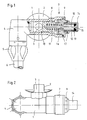
- Fig. 1 eine Gasanschlußarmatur teilweise geschnitten in Seitenansicht
- Fig. 2 dieselbe Gasanschlußarmatur in Draufsicht.
- Fig. 1 shows a gas connection fitting partially cut in side view
- Fig. 2 the same gas connection fitting in plan view.
In einem Gehäuse 1 mit einem Anschlußstutzen 2 für einen Gaseintritt 3 ist auf einer Seite ein als Steckdose ausgebildet-5 Anschlußstück 4 für die Verbindung mit einem Stecker 5 am Ende eines Gasschlauches 6 angeordnet, der zu einem Verbraucher, beispielsweise einem Gasherd führt. In dem Anschlußstück 4 ist eine nicht dargestellte und auch nicht beschriebene - Ventileinrichtung angeordnet, die mit dem Einführen des Steckers 5 geöffnet und mit dem Abziehen des Steckers 5 wieder geschlossen wird.In a
Auf der dem Anschlußstück 4 gegenüberliegenden Seite ist am bzw. im Gehäuse 1 ein zusätzliches Brandschutzventil 7 angeordnet, welches im wesentlichen aus einem Ventilkörper 8, einem Deckel 9, einer Führungsstange 10, einer Feder 11, einem Stützrohr 12, einem Schmelzkörper 13 und einer Schutzhülse 14 besteht.On the side opposite the
Die Führungsstange 10 durchdringt den Deckel 9 und ist am inneren Ende mit einem Gewinde im Ventilkörper 8 verankert. Am gegenüberliegenden, äußeren Ende der Führungsstange 10 ist ein Schraubkopf 15 ausgebildet, der den Schmelzkörper 13 übergreift. Zwischen dem Ventilkörper 8 und den Deckel 9 ist in einem zylindrischen Hohlraum 16 die Feder 11 konzentrisch zur Führungsstange 10 angeordnet und vorgespannt.The
Der Deckel 9 und die Schutzhülse 14 sind mit Dichtungen 17 gasdicht zum Gehäuse 1 hin befestigt.The
Im Brandfall wird der Schmelzkörper 13 aufgeweicht, so daß sich der Schraubkopf 15 unter der Wirkung der Feder 11 aus seiner Abstützung herausziehen kann. Dabei wird der Ventilkörper 8 schlagartig in das Gehäuse 1 hineingedrückt und verschließt gegen einen Konus 18 den Gaseintritt 3. Danach kann kein weiteres Gas mehr ausströmen, wenn der Gasschlauch 6 durch den Brand zerstört wird.In the event of fire, the
- 1 Gehäuse1 housing
- 2 Anschlußstutzen2 connecting pieces
- 3 Gaseintritt3 gas inlet
- 4 Anschlußstück4 connector
- 5 Stecker5 plugs
- 6 Gasschlauch6 gas hose
- 7 Brandschutzventil7 fire protection valve
- 8 Ventilkörper8 valve body
- 9 Deckel9 lids
- 10 Führungsstange10 guide rod
- 11 Feder11 spring
- 12 Stützrohr12 support tube
- 13 Schmelzkörper13 melting bodies
- 14 Schutzhülse14 protective sleeve
- 15 Schraubkopf15 screw head
- 16 Hohlraum16 cavity
- 17 Dichtung17 seal
- 18 Konus18 cone
Claims (5)
dadurch gekennzeichnet,
daß der Ventilkörper (8) mit einer Führungsstange (10) gegen den Schmelzkörper (13) vorgespannt ist,
daß die Führungsstange (10) einen das Gehäuse (1) verschließenden Deckel (9) durchdringt,
daß die Feder (11) einerseits am Ventilkörper (8) und andererseits an der Innenseite des Deckels (9) abgestützt ist und
daß der Schmelzkörper (13) mit einem Stützrohr (12) an der Außenseite des Deckels (9) abgestützt ist.1. Gas connection fitting for gas hoses (6) with a plug (5) for securing a gas line in the event of fire with a housing (1) in which a valve body (8) with a spring (11) is biased against a melting body (13), wherein the valve body (8) is automatically moved into its closed position after the melting body (13) has softened,
characterized,
that the valve body (8) is biased against the melting body (13) with a guide rod (10),
that the guide rod (10) penetrates a cover (9) closing the housing (1),
that the spring (11) is supported on the one hand on the valve body (8) and on the other hand on the inside of the cover (9) and
that the melting body (13) is supported with a support tube (12) on the outside of the cover (9).
Priority Applications (1)
| Application Number | Priority Date | Filing Date | Title |
|---|---|---|---|
| AT89109299T ATE91328T1 (en) | 1988-05-27 | 1989-05-23 | GAS CONNECTION FITTING. |
Applications Claiming Priority (2)
| Application Number | Priority Date | Filing Date | Title |
|---|---|---|---|
| DE3817971 | 1988-05-27 | ||
| DE3817971A DE3817971A1 (en) | 1988-05-27 | 1988-05-27 | GAS CONNECTION FITTING |
Publications (2)
| Publication Number | Publication Date |
|---|---|
| EP0343615A1 true EP0343615A1 (en) | 1989-11-29 |
| EP0343615B1 EP0343615B1 (en) | 1993-07-07 |
Family
ID=6355201
Family Applications (1)
| Application Number | Title | Priority Date | Filing Date |
|---|---|---|---|
| EP89109299A Expired - Lifetime EP0343615B1 (en) | 1988-05-27 | 1989-05-23 | Gas supply fitting |
Country Status (3)
| Country | Link |
|---|---|
| EP (1) | EP0343615B1 (en) |
| AT (1) | ATE91328T1 (en) |
| DE (2) | DE3817971A1 (en) |
Cited By (8)
| Publication number | Priority date | Publication date | Assignee | Title |
|---|---|---|---|---|
| DE4220054C1 (en) * | 1992-06-19 | 1993-09-02 | Paul Isphording Metallwerke Gmbh & Co Kg, 57439 Attendorn, De | |
| DE29606948U1 (en) * | 1996-04-16 | 1996-06-27 | Streif Hans | Temperature sensitive shut-off valve |
| EP0802359A3 (en) * | 1996-04-17 | 1998-04-29 | Circle Seal Controls, Inc. | Gas cylinder thermal relief valve |
| EP0903520A1 (en) * | 1997-09-17 | 1999-03-24 | VSH Fabrieken B.V. | Thermal gas valve fitting |
| WO2000004310A2 (en) | 1998-07-13 | 2000-01-27 | Mertik Maxitrol Gmbh & Co. Kg | Safety device for cutting off gas pipelines |
| GB2393770A (en) * | 2004-01-17 | 2004-04-07 | Glenson | End fitting |
| EP1589316A1 (en) * | 2004-04-20 | 2005-10-26 | Tda Armements S.A.S. | Irreversible snap action temperature detector and application of such a detector and use of such a detector for the deconfinement of ammunition |
| WO2021151607A1 (en) * | 2020-01-31 | 2021-08-05 | Robert Bosch Gmbh | Device for storing compressed gas, vehicle |
Families Citing this family (5)
| Publication number | Priority date | Publication date | Assignee | Title |
|---|---|---|---|---|
| DE9017534U1 (en) * | 1990-12-28 | 1991-03-21 | Streif, Hans, Magliaso, Lugano, Ch | |
| DE4131859A1 (en) * | 1991-09-25 | 1993-04-01 | Mertik Regelungstechnik Gmbh | FIRE PROTECTION VALVE WITH CLOSING SPRING FOR AUTOMATIC SHUT-OFF OF PIPES |
| DE4422241A1 (en) * | 1994-06-24 | 1996-01-11 | Mertik Maxitrol Gmbh & Co Kg | Thermal valve lock for automatically shutting off lines |
| DE19608165C1 (en) * | 1996-03-04 | 1997-11-06 | Mertik Maxitrol Gmbh & Co Kg | Thermal valve lock for automatically shutting off lines |
| DE19810223C1 (en) | 1998-03-10 | 1999-05-27 | Mertik Maxitrol Gmbh & Co Kg | Thermally actuated obturator for pipes |
Citations (6)
| Publication number | Priority date | Publication date | Assignee | Title |
|---|---|---|---|---|
| US288271A (en) * | 1883-11-13 | Island | ||
| US3842853A (en) * | 1970-04-06 | 1974-10-22 | Otis Eng Corp | Fire safety valve |
| US3877476A (en) * | 1973-08-22 | 1975-04-15 | Kenco Engineering Company | Heat actuated valve |
| US3955589A (en) * | 1974-06-03 | 1976-05-11 | Rodney Thomas Beazley | Fluid isolating valve |
| US4271857A (en) * | 1979-04-30 | 1981-06-09 | Cameron Iron Works, Inc. | Fire safe valve |
| US4540012A (en) * | 1983-04-18 | 1985-09-10 | Gray Tool Company | Temperature sensitive valve bonnet assembly |
Family Cites Families (2)
| Publication number | Priority date | Publication date | Assignee | Title |
|---|---|---|---|---|
| DE2147957C2 (en) * | 1971-09-25 | 1975-02-13 | Tuboflex Kg, Fritz Bergoefer Und Co, 2000 Hamburg | Safety hose connection tap |
| DE8709338U1 (en) * | 1987-07-07 | 1987-08-20 | Johann Baptist Rombach Gmbh & Co Kg, 7500 Karlsruhe, De |
-
1988
- 1988-05-27 DE DE3817971A patent/DE3817971A1/en not_active Withdrawn
-
1989
- 1989-05-23 AT AT89109299T patent/ATE91328T1/en not_active IP Right Cessation
- 1989-05-23 DE DE8989109299T patent/DE58904861D1/en not_active Expired - Fee Related
- 1989-05-23 EP EP89109299A patent/EP0343615B1/en not_active Expired - Lifetime
Patent Citations (6)
| Publication number | Priority date | Publication date | Assignee | Title |
|---|---|---|---|---|
| US288271A (en) * | 1883-11-13 | Island | ||
| US3842853A (en) * | 1970-04-06 | 1974-10-22 | Otis Eng Corp | Fire safety valve |
| US3877476A (en) * | 1973-08-22 | 1975-04-15 | Kenco Engineering Company | Heat actuated valve |
| US3955589A (en) * | 1974-06-03 | 1976-05-11 | Rodney Thomas Beazley | Fluid isolating valve |
| US4271857A (en) * | 1979-04-30 | 1981-06-09 | Cameron Iron Works, Inc. | Fire safe valve |
| US4540012A (en) * | 1983-04-18 | 1985-09-10 | Gray Tool Company | Temperature sensitive valve bonnet assembly |
Cited By (11)
| Publication number | Priority date | Publication date | Assignee | Title |
|---|---|---|---|---|
| DE4220054C1 (en) * | 1992-06-19 | 1993-09-02 | Paul Isphording Metallwerke Gmbh & Co Kg, 57439 Attendorn, De | |
| DE29606948U1 (en) * | 1996-04-16 | 1996-06-27 | Streif Hans | Temperature sensitive shut-off valve |
| EP0802359A3 (en) * | 1996-04-17 | 1998-04-29 | Circle Seal Controls, Inc. | Gas cylinder thermal relief valve |
| EP0903520A1 (en) * | 1997-09-17 | 1999-03-24 | VSH Fabrieken B.V. | Thermal gas valve fitting |
| WO2000004310A2 (en) | 1998-07-13 | 2000-01-27 | Mertik Maxitrol Gmbh & Co. Kg | Safety device for cutting off gas pipelines |
| DE19831283C1 (en) * | 1998-07-13 | 2000-02-24 | Mertik Maxitrol Gmbh & Co Kg | Safety device for shutting off gas-bearing piping systems |
| GB2393770A (en) * | 2004-01-17 | 2004-04-07 | Glenson | End fitting |
| GB2393770B (en) * | 2004-01-17 | 2006-05-10 | Glenson | End fitting |
| EP1589316A1 (en) * | 2004-04-20 | 2005-10-26 | Tda Armements S.A.S. | Irreversible snap action temperature detector and application of such a detector and use of such a detector for the deconfinement of ammunition |
| WO2021151607A1 (en) * | 2020-01-31 | 2021-08-05 | Robert Bosch Gmbh | Device for storing compressed gas, vehicle |
| US11953155B2 (en) | 2020-01-31 | 2024-04-09 | Robert Bosch Gmbh | Device for storing compressed gas, vehicle |
Also Published As
| Publication number | Publication date |
|---|---|
| ATE91328T1 (en) | 1993-07-15 |
| DE3817971A1 (en) | 1989-11-30 |
| DE58904861D1 (en) | 1993-08-12 |
| EP0343615B1 (en) | 1993-07-07 |
Similar Documents
| Publication | Publication Date | Title |
|---|---|---|
| EP0343615B1 (en) | Gas supply fitting | |
| DE3029892C2 (en) | Throttle device for smoke exhaust pipes | |
| DE2510972B2 (en) | Flame-blocking device to be switched on in a gas pipe | |
| DE3308877C2 (en) | ||
| EP0574677B1 (en) | Safety gas outlet | |
| DE4224635C2 (en) | Medium monitoring probe | |
| DE19813307B4 (en) | Shut-off valve with a ball valve | |
| DE3817970C1 (en) | ||
| DE2044492B2 (en) | COMBUSTION PIPE CONNECTION COUPLING | |
| DE3111163A1 (en) | Device for the sealed fire-protected bushing (passage) of a cable or the like through a fire-resistant fire wall | |
| DE8209703U1 (en) | HOSE BREAKAGE PROTECTION FOR GAS SYSTEMS | |
| DE19944231C2 (en) | Device for shutting off frost-proof fittings before they are fully assembled | |
| DE19637825C1 (en) | Locking valve | |
| DE3132408C2 (en) | ||
| DE3722387C1 (en) | Safety shut-off fitting for a gas conduit | |
| AT336223B (en) | DEVICE FOR FASTENING A CONNECTOR IN A CYLINDRICAL BORE OF A RADIATOR FOR CENTRAL HEATING SYSTEMS OR TO CLOSE THE FACE OF THE RADIATOR | |
| DE3318438C2 (en) | Hydrant with bypass separation point | |
| EP0931970A1 (en) | Tapping and cut-off apparatus for pipes under pressure | |
| DE10203306B4 (en) | flow Switch | |
| DE3805845C1 (en) | ||
| DE3212427A1 (en) | SHUT-OFF ORGAN | |
| DE19747497C2 (en) | Shut-off device with a ball valve | |
| DE2820797C2 (en) | Tube body for an oxygen lance | |
| EP0363644B1 (en) | Gas supply fitting | |
| WO1997032148A1 (en) | Pipeline safety valve valve |
Legal Events
| Date | Code | Title | Description |
|---|---|---|---|
| PUAI | Public reference made under article 153(3) epc to a published international application that has entered the european phase |
Free format text: ORIGINAL CODE: 0009012 |
|
| AK | Designated contracting states |
Kind code of ref document: A1 Designated state(s): AT BE CH DE FR GB IT LI NL |
|
| 17P | Request for examination filed |
Effective date: 19900428 |
|
| 17Q | First examination report despatched |
Effective date: 19910731 |
|
| GRAA | (expected) grant |
Free format text: ORIGINAL CODE: 0009210 |
|
| ITF | It: translation for a ep patent filed |
Owner name: ING. ZINI MARANESI & C. S.R.L. |
|
| AK | Designated contracting states |
Kind code of ref document: B1 Designated state(s): AT BE CH DE FR GB IT LI NL |
|
| PG25 | Lapsed in a contracting state [announced via postgrant information from national office to epo] |
Ref country code: NL Effective date: 19930707 Ref country code: FR Effective date: 19930707 Ref country code: BE Effective date: 19930707 |
|
| REF | Corresponds to: |
Ref document number: 91328 Country of ref document: AT Date of ref document: 19930715 Kind code of ref document: T |
|
| GBT | Gb: translation of ep patent filed (gb section 77(6)(a)/1977) |
Effective date: 19930709 |
|
| REF | Corresponds to: |
Ref document number: 58904861 Country of ref document: DE Date of ref document: 19930812 |
|
| EN | Fr: translation not filed | ||
| NLV1 | Nl: lapsed or annulled due to failure to fulfill the requirements of art. 29p and 29m of the patents act | ||
| PLBE | No opposition filed within time limit |
Free format text: ORIGINAL CODE: 0009261 |
|
| STAA | Information on the status of an ep patent application or granted ep patent |
Free format text: STATUS: NO OPPOSITION FILED WITHIN TIME LIMIT |
|
| PGFP | Annual fee paid to national office [announced via postgrant information from national office to epo] |
Ref country code: AT Payment date: 19940525 Year of fee payment: 6 |
|
| PGFP | Annual fee paid to national office [announced via postgrant information from national office to epo] |
Ref country code: GB Payment date: 19940602 Year of fee payment: 6 |
|
| PGFP | Annual fee paid to national office [announced via postgrant information from national office to epo] |
Ref country code: CH Payment date: 19940620 Year of fee payment: 6 |
|
| 26N | No opposition filed | ||
| PG25 | Lapsed in a contracting state [announced via postgrant information from national office to epo] |
Ref country code: GB Effective date: 19950523 Ref country code: AT Effective date: 19950523 |
|
| PG25 | Lapsed in a contracting state [announced via postgrant information from national office to epo] |
Ref country code: LI Effective date: 19950531 Ref country code: CH Effective date: 19950531 |
|
| GBPC | Gb: european patent ceased through non-payment of renewal fee |
Effective date: 19950523 |
|
| REG | Reference to a national code |
Ref country code: CH Ref legal event code: PL |
|
| PGFP | Annual fee paid to national office [announced via postgrant information from national office to epo] |
Ref country code: DE Payment date: 19960715 Year of fee payment: 8 |
|
| PG25 | Lapsed in a contracting state [announced via postgrant information from national office to epo] |
Ref country code: DE Free format text: LAPSE BECAUSE OF NON-PAYMENT OF DUE FEES Effective date: 19980203 |
|
| PG25 | Lapsed in a contracting state [announced via postgrant information from national office to epo] |
Ref country code: IT Free format text: LAPSE BECAUSE OF NON-PAYMENT OF DUE FEES;WARNING: LAPSES OF ITALIAN PATENTS WITH EFFECTIVE DATE BEFORE 2007 MAY HAVE OCCURRED AT ANY TIME BEFORE 2007. THE CORRECT EFFECTIVE DATE MAY BE DIFFERENT FROM THE ONE RECORDED. Effective date: 20050523 |