EP1589304B1 - Vorrichtung zum Umschalten von Kühlmittelrohren einer Klimaanlage - Google Patents
Vorrichtung zum Umschalten von Kühlmittelrohren einer Klimaanlage Download PDFInfo
- Publication number
- EP1589304B1 EP1589304B1 EP05251968.3A EP05251968A EP1589304B1 EP 1589304 B1 EP1589304 B1 EP 1589304B1 EP 05251968 A EP05251968 A EP 05251968A EP 1589304 B1 EP1589304 B1 EP 1589304B1
- Authority
- EP
- European Patent Office
- Prior art keywords
- refrigerant
- open
- valve
- close
- pipe
- Prior art date
- Legal status (The legal status is an assumption and is not a legal conclusion. Google has not performed a legal analysis and makes no representation as to the accuracy of the status listed.)
- Ceased
Links
- 239000003507 refrigerant Substances 0.000 title claims description 204
- 239000007769 metal material Substances 0.000 claims description 2
- 238000000034 method Methods 0.000 description 4
- 239000007788 liquid Substances 0.000 description 3
- 238000007906 compression Methods 0.000 description 2
- 238000001816 cooling Methods 0.000 description 2
- 238000001704 evaporation Methods 0.000 description 2
- 238000010257 thawing Methods 0.000 description 2
- 238000007664 blowing Methods 0.000 description 1
- 230000006835 compression Effects 0.000 description 1
- 230000005494 condensation Effects 0.000 description 1
- 238000009833 condensation Methods 0.000 description 1
- 238000007599 discharging Methods 0.000 description 1
- 238000005265 energy consumption Methods 0.000 description 1
- 230000008020 evaporation Effects 0.000 description 1
- 238000005461 lubrication Methods 0.000 description 1
- 238000007789 sealing Methods 0.000 description 1
- 230000002123 temporal effect Effects 0.000 description 1
Images


Classifications
-
- F—MECHANICAL ENGINEERING; LIGHTING; HEATING; WEAPONS; BLASTING
- F25—REFRIGERATION OR COOLING; COMBINED HEATING AND REFRIGERATION SYSTEMS; HEAT PUMP SYSTEMS; MANUFACTURE OR STORAGE OF ICE; LIQUEFACTION SOLIDIFICATION OF GASES
- F25B—REFRIGERATION MACHINES, PLANTS OR SYSTEMS; COMBINED HEATING AND REFRIGERATION SYSTEMS; HEAT PUMP SYSTEMS
- F25B41/00—Fluid-circulation arrangements
- F25B41/20—Disposition of valves, e.g. of on-off valves or flow control valves
- F25B41/24—Arrangement of shut-off valves for disconnecting a part of the refrigerant cycle, e.g. an outdoor part
-
- F—MECHANICAL ENGINEERING; LIGHTING; HEATING; WEAPONS; BLASTING
- F25—REFRIGERATION OR COOLING; COMBINED HEATING AND REFRIGERATION SYSTEMS; HEAT PUMP SYSTEMS; MANUFACTURE OR STORAGE OF ICE; LIQUEFACTION SOLIDIFICATION OF GASES
- F25B—REFRIGERATION MACHINES, PLANTS OR SYSTEMS; COMBINED HEATING AND REFRIGERATION SYSTEMS; HEAT PUMP SYSTEMS
- F25B49/00—Arrangement or mounting of control or safety devices
- F25B49/02—Arrangement or mounting of control or safety devices for compression type machines, plants or systems
- F25B49/022—Compressor control arrangements
-
- F—MECHANICAL ENGINEERING; LIGHTING; HEATING; WEAPONS; BLASTING
- F25—REFRIGERATION OR COOLING; COMBINED HEATING AND REFRIGERATION SYSTEMS; HEAT PUMP SYSTEMS; MANUFACTURE OR STORAGE OF ICE; LIQUEFACTION SOLIDIFICATION OF GASES
- F25B—REFRIGERATION MACHINES, PLANTS OR SYSTEMS; COMBINED HEATING AND REFRIGERATION SYSTEMS; HEAT PUMP SYSTEMS
- F25B2400/00—General features or devices for refrigeration machines, plants or systems, combined heating and refrigeration systems or heat-pump systems, i.e. not limited to a particular subgroup of F25B
- F25B2400/04—Refrigeration circuit bypassing means
-
- F—MECHANICAL ENGINEERING; LIGHTING; HEATING; WEAPONS; BLASTING
- F25—REFRIGERATION OR COOLING; COMBINED HEATING AND REFRIGERATION SYSTEMS; HEAT PUMP SYSTEMS; MANUFACTURE OR STORAGE OF ICE; LIQUEFACTION SOLIDIFICATION OF GASES
- F25B—REFRIGERATION MACHINES, PLANTS OR SYSTEMS; COMBINED HEATING AND REFRIGERATION SYSTEMS; HEAT PUMP SYSTEMS
- F25B2400/00—General features or devices for refrigeration machines, plants or systems, combined heating and refrigeration systems or heat-pump systems, i.e. not limited to a particular subgroup of F25B
- F25B2400/07—Details of compressors or related parts
- F25B2400/075—Details of compressors or related parts with parallel compressors
-
- F—MECHANICAL ENGINEERING; LIGHTING; HEATING; WEAPONS; BLASTING
- F25—REFRIGERATION OR COOLING; COMBINED HEATING AND REFRIGERATION SYSTEMS; HEAT PUMP SYSTEMS; MANUFACTURE OR STORAGE OF ICE; LIQUEFACTION SOLIDIFICATION OF GASES
- F25B—REFRIGERATION MACHINES, PLANTS OR SYSTEMS; COMBINED HEATING AND REFRIGERATION SYSTEMS; HEAT PUMP SYSTEMS
- F25B2500/00—Problems to be solved
- F25B2500/26—Problems to be solved characterised by the startup of the refrigeration cycle
-
- F—MECHANICAL ENGINEERING; LIGHTING; HEATING; WEAPONS; BLASTING
- F25—REFRIGERATION OR COOLING; COMBINED HEATING AND REFRIGERATION SYSTEMS; HEAT PUMP SYSTEMS; MANUFACTURE OR STORAGE OF ICE; LIQUEFACTION SOLIDIFICATION OF GASES
- F25B—REFRIGERATION MACHINES, PLANTS OR SYSTEMS; COMBINED HEATING AND REFRIGERATION SYSTEMS; HEAT PUMP SYSTEMS
- F25B2600/00—Control issues
- F25B2600/02—Compressor control
- F25B2600/026—Compressor control by controlling unloaders
- F25B2600/0261—Compressor control by controlling unloaders external to the compressor
Definitions
- the present invention relates to an apparatus for converting a refrigerant pipe of an air conditioner, and more particularly, to an apparatus for converting a refrigerant pipe of an air conditioner capable of preventing a backflow of a refrigerant and capable of fast re-operating an air conditioner by removing a pressure difference between a refrigerant suction side and a refrigerant discharge side before re-operating the air conditioner.
- a refrigerating cycle of an air conditioner repeatedly performs a compression process, a condensation process, an expansion process, and an evaporation process.
- the refrigerating cycle is composed of: a compressor for compressing a refrigerant of a low temperature and a low pressure and thereby converting into a refrigerant of a high temperature and a high pressure; a condenser for condensing a refrigerant of a high temperature and a high pressure into a liquid state; an expander for expanding a condensed refrigerant and thereby converting into a refrigerant of a low temperature and a low pressure; and refrigerant pipes for connecting the compressor, the condenser, and the expander one another.
- JP H10-238879 discloses compressors with the same capacity connected in parallel to a refrigerant circuit while oil reservoirs of bottom units thereof are connected by an oil equilibrium pipe, and the oil equilibrium pipe is connected to another outdoor unit through a between units oil equilibrium pipe.
- an oil equilibrium solenoid valve and an oil operating valve are interposed in the between unit oil equilibrium pipe and bypass circuits are connected in parallel to a pipe between the discharging pipeline and the suction pipeline of the compressors.
- Capacity controlling solenoid valves and capillary tubes are interposed in the bypass circuits respectively.
- JP H03-039866 discloses a rotating speed variable compressor which is varied at its operating frequency by an inverter from 1.2 horsepower of minimum capacity to 4 horsepower of maximum capacity.
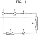
- FIG. 1 is a conceptual view showing a refrigerating cycle of an air conditioner in accordance with the conventional art.
- the conventional air conditioner comprises: a compressor 1 for compressing a refrigerant; a check valve 2 for preventing a backflow of a refrigerant discharged from the compressor 1; a condenser 3 for condensing a compressed refrigerant into a liquid state; and an evaporator 4 for evaporating a condensed refrigerant.
- An electronic expansion valve 5 for controlling a flow of a refrigerant according to an operated state of the compressor 11 is installed between the condenser and the evaporator 40. Also, an accumulator for preventing a liquid refrigerant that has not been vaporized from being introduced into the compressor 11 is installed between the evaporator 40 and the compressor 11.
- the compressed refrigerant is introduced into the condenser 30 via the check valve 2 thus to be condensed.
- the condensed refrigerant is introduced into the evaporator 40 via the electronic expansion valve 5.
- the refrigerant introduced into the evaporator 40 is vaporized thus to form cool air, and the cool air is blown indoors through a cool air vent of an indoor unit (not shown).
- FIG. 2 is a perspective view showing an outdoor unit of the conventional air conditioner having plural compressors
- FIG. 3 is a perspective view showing refrigerant pipes and check valves connected to the plural compressors of the conventional air conditioner.
- an outdoor unit 10 of the conventional air conditioner includes: plural compressors 11 and 12 for compressing a refrigerant into a high temperature and a high pressure; a condenser 30 for condensing a refrigerant of a high temperature and a high pressure; and an outdoor fan 14 for blowing external air to the condenser 30.
- An unexplained reference numeral 15 denotes a cover.
- a refrigerant suction pipe 11 a and a refrigerant discharge pipe 11b are respectively formed at one side and another side of the first compressor 11. Also, a refrigerant suction pipe 12 a and a refrigerant discharge pipe 12b are respectively formed at one side and another side of the second compressor 12.
- the refrigerant suction pipes 11 a and 12a are connected to each other in parallel, and the refrigerant discharge pipes 11b and 12b are connected to each other in parallel.
- a check valve 2 for preventing a backflow of a refrigerant is installed at each refrigerant discharge pipe 11b and 12b.
- Unexplained reference numeral 6 denotes an accumulator
- 31 denotes a refrigerant circulation pipe of a condenser
- 32 denotes a refrigerant circulation pipe of a suction side of the compressor.
- the first compressor 11 and the second compressor 12 are respectively operated thereby to suck a refrigerant through the refrigerant suction pipes 11a and 12a and compress.
- the compressed refrigerant is introduced into the condenser 30 through the refrigerant discharge pipes 11b and 12b via the check valve 2.
- the refrigerant is condensed by the condenser 30 of FIG. 2 , and then passes through the evaporator of FIG. 1 thus to be vaporized and to form cool air.
- the cool air is blown indoors through a cool air vent of an indoor unit (not shown).
- the refrigerant vaporized while passing through the evaporator 40 is introduced into the first compressor 11 and the second compressor 12 via the refrigerant circulation pipe 32 and the refrigerant suction pipes 11a and 12a. The above processes are repeated.
- a user can temporarily stop the operation of the air conditioner in order to perform a defrosting operation to remove frost unnecessarily formed during a cooling operation and then reoperate the air conditioner.
- a pressure difference between a refrigerant suction side and a refrigerant discharge side is generated and thereby the air conditioner can not be re-operated within a certain time.
- the user has to re-operate the air conditioner after removing a pressure difference between a refrigerant suction side (a lower side of the check valve) and a refrigerant discharge side (an upper side of the check valve). According to this, it takes a lot of time to re-operate the air conditioner.
- the above phenomenon is generated more severely by the check valve 2 installed at the refrigerant discharge pipes 11b and 12b. Even if the check valve 2 prevents a backflow of a refrigerant while the air conditioner is operated, the check valve causes a pressure difference between the refrigerant suction side and the refrigerant discharge side at the time of re-operating the air conditioner thereby to take a lot of time to re-operate the air conditioner.
- an aim of the present invention is to provide an apparatus for converting a refrigerant pipe of an air conditioner capable of preventing a backflow of a refrigerant and capable of fast re-operating an air conditioner by removing a pressure difference between a refrigerant suction side and a refrigerant discharge side before re-operating the air conditioner.
- an apparatus for converting a refrigerant pipe of an air conditioner comprising: a valve housing installed at a position where respective refrigerant discharge pipes of plural compressors are put together, having a valve space portion therein, and having a first refrigerant inlet, a second refrigerant inlet, a detour refrigerant inlet, a refrigerant outlet and a bypass outlet at upper and lower sides thereof; a bypass pipe for connecting the refrigerant outlet of the valve housing to refrigerant suction pipes of the compressors so that a refrigerant discharged from each refrigerant discharge pipe of the plural compressors can be introduced to the refrigerant suction pipes of the plural compressors; an open/close valve slidably installed at the valve space portion of the valve housing so that a refrigerant discharged from the refrigerant discharge pipes can be selectively introduced into a refrigerant
- the valve housing is composed of: a first refrigerant inlet formed at one lower portion thereof, for connecting the valve space portion and a refrigerant discharge pipe of a first compressor; a second refrigerant inlet formed at another lower portion thereof, for connecting the valve space portion and a refrigerant discharge pipe of a second compressor; a refrigerant outlet formed at one upper portion thereof and connected to the refrigerant circulation pipe of the condenser; a bypass outlet formed at another upper portion thereof and connected to the refrigerant circulation pipe of the condenser; and a detour refrigerant inlet formed at a side of the first refrigerant inlet, for connecting the valve space portion and the first refrigerant inlet.
- the open/close valve driving means is composed of: a pair of springs installed at both sides of the open/close valve; and a pair of electromagnets installed at both sides of the valve housing, for overcoming an elastic force of the springs and pulling the open/close valve.
- the open/close valve is composed of: a first open/close portion for opening and closing the refrigerant outlet; a second open/close portion for opening and closing the bypass outlet; and a connection portion for connecting the first open/close portion and the second open/close portion.
- the first open/close portion and the second open/close portion correspond to each other, and are adhered to an inner wall of the valve space portion with the same diameter.
- the connection portion is formed to have a diameter Shorter than diameters of the first open/close portion and the second open/close portion.
- One end of a first refrigerant discharge pipe of a first compressor and one end of a second refrigerant discharge pipe of a second compressor are respectively fitted into the first refrigerant inlet and the second refrigerant inlet of the valve housing with a sealed state. Also, one end of the refrigerant circulation pipe and one end of the bypass pipe are respectively fitted into the refrigerant outlet and the bypass outlet with a sealed state.
- FIG. 4 is a perspective view showing an apparatus for converting a refrigerant pipe of an air conditioner according to the present invention
- FIG. 5 is a longitudinal section view showing an operation state of the apparatus for converting a refrigerant pipe of an air conditioner according to the present invention in case that both a first compressor and a second compressor are stopped
- FIG. 6 is a longitudinal section view showing an operation state of the apparatus for converting a refrigerant pipe of an air conditioner according to the present invention in case that both the first compressor and the second compressor are operated
- FIG. 7 is a longitudinal section view showing an operation state of the apparatus for converting a refrigerant pipe of an air conditioner according to the present invention in case that only the first compressor is operated.
- a cylindrical valve housing 110 is installed in the middle of refrigerant discharge pipes 11b and 12b, that is, at a position where refrigerant discharge pipes 11 b and 12b of a first compressor 11 and a second compressor 12 are put together.
- a valve space portion 111 is long formed in the valve housing 110 in a horizontal direction.
- the valve housing 110 is composed of: a first refrigerant inlet 112 formed at one lower portion thereof, for connecting the valve space portion 111 and the refrigerant discharge pipe 11b of the first compressor 11; a second refrigerant inlet 113 formed at another lower portion thereof, for connecting the valve space portion 111 and the refrigerant discharge pipe 12b of the second compressor 12; a refrigerant outlet 114 formed at one upper portion thereof and connected to a refrigerant circulation pipe 31 of the condenser 30; a bypass outlet 115 formed at another upper portion thereof and connected to the refrigerant circulation pipe 31 of the condenser 30; and a detour refrigerant inlet 116 formed at a side of the first refrigerant inlet 112, for connecting the valve space portion 111 and the first refrigerant inlet 112.
- One end of the first refrigerant discharge pipe 11 b of the first compressor 11 and one end of the second refrigerant discharge pipe 12b of the second compressor 12 are respectively fitted into the first refrigerant inlet 112 and the second refrigerant inlet 113 of the valve housing 110. Also, one end of the refrigerant circulation pipe 31 and one end of the bypass pipe 120 are respectively fitted into the refrigerant outlet 114 and the bypass outlet 115.
- a sealing member 160 is installed at an outer circumferential surface of the fitting portion, thereby preventing a refrigerant flowing through the valve space portion 111 of the valve housing 110 from being leaked to the outside.
- An exhaust hole 110a for exhausting gas is formed at a lower portion of the valve housing 110.
- the bypass pipe 120 is installed between the refrigerant outlet 114 of the valve housing 110 and the refrigerant suction pipes 11a and 12a of the first compressor 11 and the second compressor 12 so that a refrigerant discharged from each refrigerant discharge pipe 11 band 12b of the first compressor 11 and the second compressor 12 can be introduced into the refrigerant suction pipes 11a and 12a of the first compressor 11 and the second compressor 12.
- An open/close valve 130 of a metal material is slidably installed at the valve space portion 111 of the valve housing 110 so that a refrigerant discharged from the refrigerant discharge pipes 11 b and 12b can be selectively introduced into the refrigerant circulation pipe 31 of the condenser 30 or the bypass pipe 120.
- Lubrication oil (not shown) is deposited to an inner wall 111a of the valve space portion 111 thereby to smoothly operate the open/close valve 130.
- the open/close valve 130 is composed of: a first open/close portion 131 for opening and closing the refrigerant outlet 114; a second open/close portion 132 for opening and closing the bypass outlet 115; and a connection portion 133 for connecting the first open/close portion 131 and the second open/close portion 132.
- the first open/close portion 131 and the second open/close portion 132 correspond to each other, and are adhered to the inner wall 111a of the valve space portion 111 with the same diameter.
- the connection portion 133 for connecting the first open/close portion 131 and the second open/close portion 132 is formed to have a diameter shorter than diameters of the first open/close portion 131 and the second open/close portion 132.
- An open/close valve driving means 140 for driving the open/close vale 130 is installed at a side of the valve housing 110.
- the open/close valve driving means 140 is composed of: a pair of springs 141 and 141' installed at both sides of the open/close valve 130; and a pair of electromagnets 142 and 142' installed at both sides of the valve housing 110, for overcoming an elastic force of the springs 141 and 141' and pulling the open/close valve 130.
- the first open/close portion 131 or the second open/close portion 132 of the open/close valve 130 selectively opens and closes the first refrigerant inlet 112, the second refrigerant inlet 113, the refrigerant outlet 114 and the bypass outlet 115 thereby to control a flow of a refrigerant. Then, the springs 141 and 141' restore the open/close vale 130 to the original position.
- the electromagnets 142 and 142' are not magnetized and thereby the open/close valve 130 is positioned in the middle of the valve space portion 111 of the valve housing 110.
- the first open/close portion 131 closes the refrigerant outlet 114 and the detour refrigerant inlet 116
- the second open/close valve 132 opens the bypass outlet 115, thereby connecting the first refrigerant inlet 112 and the second refrigerant inlet 113 to the bypass outlet 115.
- the first open/close portion 131 closes the refrigerant outlet 114 and the detour refrigerant inlet 116 and at the same time the second open/close portion 132 opens the bypass outlet 115. According to this, a backflow of a refrigerant flowing in the refrigerant circulation pipe 31 can be effectively prevented.
- the electromagnet 142 is magnetized and thereby the open/close valve 130 overcomes an elastic force of the spring 141 thus to move to the left side.
- the first open/close portion 131 closes the detour refrigerant inlet 116 and at the same time the second open/close portion 132 closes the bypass outlet 115, thereby connecting the first refrigerant inlet 112 and the second refrigerant inlet 113 to the refrigerant outlet 114.
- the open/close valve 130 moves by the electromagnet 142 and thereby the first refrigerant inlet 112 and the second refrigerant inlet 113 are respectively connected to the refrigerant outlet 114, a refrigerant discharged from the refrigerant discharge pipes 11b and 12b of the first compressor 11 and the second compressor 12 passes through the valve space portion 111 thus to be introduced into the refrigerant circulation pipe 31 through the refrigerant outlet 114. Then, the refrigerant that has been introduced into the refrigerant circulation pipe 32 is circulated via the condenser 30 and the evaporator 40, and then is introduced into the refrigerant suction pipes 11 a and 12a of the first compressor 11 and the second compressor 12 through the refrigerant circulation pipe 31.
- the electromagnet 142' is magnetized and thereby the open/close valve 130 overcomes a elastic force of the spring 141' thus to move to the right side.
- the first open/close portion 131 closes the refrigerant inlet 112 and at the same time the second open/close portion 132 opens the bypass outlet 115, thereby connecting the detour refrigerant inlet 116 to the refrigerant outlet 114 and connecting the second refrigerant inlet 113 to the bypass outlet 115.
- the detour refrigerant inlet 116 is connected to the refrigerant outlet 114 and the second refrigerant outlet 113 is connected to the bypass outlet 115.
- a refrigerant discharged from the refrigerant discharge pipe 11 b of the first compressor 11 is introduced into the refrigerant circulation pipe 32 thus to be circulated via the condenser 30 and the evaporator 40.
- the refrigerant is introduced into the refrigerant suction pipes 11 a and 12a of the first compressor 11 and the second compressor 12 through the refrigerant circulation pipe 32.
- a refrigerant discharged from the refrigerant discharge pipe 12b of the second compressor 12 sequentially passes through the second refrigerant inlet 113, the valve space portion 111 and the bypass outlet 115 thereby to be introduced into the bypass pipe 120. Then, the refrigerant is introduced into the refrigerant suction pipes 11 a and 12a of the first compressor 11 and the second compressor 12 through the refrigerant circulation pipe 32.
- a backflow of a refrigerant can be effectively prevented without using the check valve.
- a refrigerant discharged from the compressor is selectively introduced into the refrigerant circulation pipe of the condenser or the bypass pipe thus to remove a pressure difference between the refrigerant suction side and the refrigerant discharge side.
- the air conditioner can be fast re-operated even after the air conditioner is stopped to perform a defrosting operation for removing frost unnecessarily formed during a cooling operation or after the air conditioner is stopped since the air conditioner reaches a temperature desired by the user. According to this, the time to re-operate the air conditioner can be greatly reduced, and the air conditioner can be operated more conveniently and efficiently.
Landscapes
- Engineering & Computer Science (AREA)
- Physics & Mathematics (AREA)
- Mechanical Engineering (AREA)
- Thermal Sciences (AREA)
- General Engineering & Computer Science (AREA)
- Compressor (AREA)
- Other Air-Conditioning Systems (AREA)
- Compression-Type Refrigeration Machines With Reversible Cycles (AREA)
- Multiple-Way Valves (AREA)
Claims (8)
- Vorrichtung zum Umwandeln einer Kühlmittelleitung einer Klimaanlage, wobei die Vorrichtung Folgendes umfasst:ein Ventilgehäuse (110), das einen Ventilraumteil (111) darin aufweist und sich aus einem ersten Kühlmitteleinlass (112), der an einem unteren Teil davon ausgebildet ist und den Ventilraumteil (111) und eine Kühlmittelabflussleitung (11b) eines ersten Verdichters (11) verbindet, einem zweiten Kühlmitteleinlass (113), der an einem anderen unteren Teil davon ausgebildet ist und den Ventilraumteil (111) und eine Kühlmittelabflussleitung (12b) eines zweiten Verdichters (12) verbindet, einem Kühlmittelauslass (114), der an einem oberen Teil davon ausgebildet ist und mit einer Kühlmittelzirkulationsleitung (31) eines Kühlers (30) verbunden ist, einem Bypass-Auslass (115), der an einem anderen oberen Teil davon ausgebildet ist und mit einer Kühlmittelzirkulationsleitung (32) des Kühlers (30) verbunden ist, und einem Umleitungskühlmitteleinlass (116), der an einer Seite des ersten Kühlmitteleinlasses (112) ausgebildet ist und den Ventilraumteil (111) mit dem ersten Kühlmitteleinlass (112) verbindet;eine Bypass-Leitung (120) zum Verbinden des Bypass-Auslasses (115) des Ventilgehäuses (110) mit der Kühlmittelzirkulationsleitung (32), die mit Kühlmittelansaugleitungen (11a, 12a) des ersten und des zweiten Verdichters (11, 12) verbunden ist;ein Auf/Zu-Ventil (130), das verschiebbar in dem Ventilraumteil (111) des Ventilgehäuses (110) installiert ist, so dass ein Kühlmittel, das in den Ventilraumteil (111) des Ventilgehäuses (110) eingebracht wird, wahlweise in die Kühlmittelzirkulationsleitung (31) des Kühlers (30) oder die Bypass-Leitung (120) eingebracht werden kann; undein Auf/Zu-Ventil-Antriebsmittel (140), das auf beiden Seiten des Auf/Zu-Ventils (130) installiert ist und das Auf/Zu-Ventil (130) antreibt.
- Vorrichtung nach Anspruch 1, wobei das Auf/Zu-Ventil (130) sich aus Folgendem zusammensetzt:einem ersten Auf/Zu-Teil (131) zum Öffnen und Schließen des Kühlmittelauslasses (114);einem zweiten Auf/Zu-Teil (132) zum Öffnen und Schließen des Bypass-Auslasses (115) undeinem Verbindungsteil (133) zum Verbinden des ersten Auf/Zu-Teils (131) und des zweiten Auf/Zu-Teils (132).
- Vorrichtung nach Anspruch 2, wobei der erste Auf/Zu-Teil (131) und der zweite Auf/Zu-Teil (132) einander entsprechen und an eine Innenwand des Ventilraumteils (111) mit demselben Durchmesser gebunden sind und der Verbindungsteil (133) so ausgebildet ist, dass er einen Durchmesser aufweist, der kürzer als Durchmesser des ersten Auf/Zu-Teils (131) und des zweiten Auf/Zu-Teils (132) ist.
- Vorrichtung nach Anspruch 1, wobei das Auf/Zu-Ventil-Antriebsmittel (140) sich aus Folgendem zusammensetzt:einem Paar Federn (141, 141'), die auf beiden Seiten des Auf/Zu-Ventils (130) installiert sind; undeinem Paar Elektromagnete (142, 142'), die auf beiden Seiten des Ventilgehäuses (110) installiert sind, zum Überwinden einer Federkraft der Federn (141, 141') und Ziehen des Auf/Zu-Ventils (130).
- Vorrichtung nach Anspruch 1, wobei das Ventilgehäuse (110) mit einer Entlüftungsöffnung (110a) an einem unteren Teil davon versehen ist.
- Vorrichtung nach Anspruch 1, wobei das Ventilgehäuse (110) eine zylindrische Form aufweist.
- Vorrichtung nach Anspruch 1, wobei ein Ende der ersten Kühlmittelabflussleitung (11b) des ersten Verdichters (11) und ein Ende der zweiten Kühlmittelabflussleitung (12b) des zweiten Verdichters (12) in den ersten Kühlmitteleinlass (112) bzw. den zweiten Kühlmitteleinlass (113) des Ventilgehäuses (110) mit einem versiegelten Zustand eingepasst sind und ein Ende der Kühlmittelzirkulationsleitung (31) und ein Ende der Bypass-Leitung (120) in den Kühlmittelauslass (114) bzw. den Bypass-Auslass (115) mit einem versiegelten Zustand eingepasst sind.
- Vorrichtung nach einem der Ansprüche 1 bis 7, wobei das Auf/Zu-Ventil (130) aus einem Metallmaterial hergestellt ist und verschiebbar an dem Ventilraumteil (111) des Ventilgehäuses (110) installiert ist, so dass ein Kühlmittel, das aus den Kühlmittelabflussleitungen (11b und 12b) abfließen gelassen wird, wahlweise in die Kühlmittelzirkulationsleitung (31) des Verdichters (30) oder die Bypass-Leitung (120) eingebracht werden kann.
Applications Claiming Priority (2)
| Application Number | Priority Date | Filing Date | Title |
|---|---|---|---|
| KR1020040027942A KR100539763B1 (ko) | 2004-04-22 | 2004-04-22 | 에어콘용 압축기의 압력 평형 장치 |
| KR2004027942 | 2004-04-22 |
Publications (3)
| Publication Number | Publication Date |
|---|---|
| EP1589304A2 EP1589304A2 (de) | 2005-10-26 |
| EP1589304A3 EP1589304A3 (de) | 2012-02-15 |
| EP1589304B1 true EP1589304B1 (de) | 2016-12-28 |
Family
ID=34940662
Family Applications (1)
| Application Number | Title | Priority Date | Filing Date |
|---|---|---|---|
| EP05251968.3A Ceased EP1589304B1 (de) | 2004-04-22 | 2005-03-30 | Vorrichtung zum Umschalten von Kühlmittelrohren einer Klimaanlage |
Country Status (4)
| Country | Link |
|---|---|
| US (1) | US7165420B2 (de) |
| EP (1) | EP1589304B1 (de) |
| KR (1) | KR100539763B1 (de) |
| CN (1) | CN100554828C (de) |
Families Citing this family (8)
| Publication number | Priority date | Publication date | Assignee | Title |
|---|---|---|---|---|
| KR100606273B1 (ko) * | 2004-10-22 | 2006-08-01 | 위니아만도 주식회사 | 공기조화기의 냉매제어장치 |
| KR100606274B1 (ko) * | 2004-12-20 | 2006-08-01 | 위니아만도 주식회사 | 다수 개의 압축기를 갖는 공기조화기의 압력평형 장치 |
| KR101172445B1 (ko) * | 2005-02-15 | 2012-08-07 | 엘지전자 주식회사 | 냉난방 동시형 멀티 에어컨 |
| KR100689902B1 (ko) * | 2005-05-19 | 2007-03-08 | 위니아만도 주식회사 | 공기조화기의 냉매제어장치 |
| KR100626757B1 (ko) | 2005-07-21 | 2006-09-25 | 주식회사 대우일렉트로닉스 | 공기조화기 |
| KR100885566B1 (ko) * | 2007-03-16 | 2009-02-24 | 엘지전자 주식회사 | 공기 조화기의 제어방법 |
| KR100853357B1 (ko) * | 2007-07-10 | 2008-08-21 | 캐리어 주식회사 | 다수 개의 압축기를 갖는 공기조화기의 압력평형장치 |
| FR2932553B1 (fr) * | 2008-06-12 | 2013-08-16 | Jean Luc Maire | Systeme reversible de recuperation d'energie calorifique par prelevement et transfert de calories d'un ou plusieurs milieux dans un autre ou plusieurs autres milieux quelconques. |
Family Cites Families (18)
| Publication number | Priority date | Publication date | Assignee | Title |
|---|---|---|---|---|
| US4167102A (en) * | 1975-12-24 | 1979-09-11 | Emhart Industries, Inc. | Refrigeration system utilizing saturated gaseous refrigerant for defrost purposes |
| US4193270A (en) * | 1978-02-27 | 1980-03-18 | Scott Jack D | Refrigeration system with compressor load transfer means |
| US5265434A (en) * | 1979-07-31 | 1993-11-30 | Alsenz Richard H | Method and apparatus for controlling capacity of a multiple-stage cooling system |
| US4474026A (en) * | 1981-01-30 | 1984-10-02 | Hitachi, Ltd. | Refrigerating apparatus |
| US4418548A (en) * | 1982-03-29 | 1983-12-06 | Trane Cac, Inc. | Variable capacity multiple compressor refrigeration system |
| US4554795A (en) * | 1983-11-14 | 1985-11-26 | Tyler Refrigeration Corporation | Compressor oil return system for refrigeration apparatus and method |
| US4537047A (en) * | 1984-03-02 | 1985-08-27 | Thermo King Corporation | Truck transport refrigeration unit |
| US4621505A (en) * | 1985-08-01 | 1986-11-11 | Hussmann Corporation | Flow-through surge receiver |
| US4750337A (en) * | 1987-10-13 | 1988-06-14 | American Standard Inc. | Oil management in a parallel compressor arrangement |
| JP2810422B2 (ja) * | 1989-07-05 | 1998-10-15 | 三洋電機株式会社 | 冷凍装置 |
| JP2748801B2 (ja) * | 1992-10-20 | 1998-05-13 | 三菱電機株式会社 | 空気調和装置 |
| WO1996000873A1 (en) * | 1994-06-29 | 1996-01-11 | Daikin Industries, Ltd. | Refrigerator |
| US5634345A (en) * | 1995-06-06 | 1997-06-03 | Alsenz; Richard H. | Oil monitoring system |
| JPH10238879A (ja) * | 1997-02-21 | 1998-09-08 | Mitsubishi Heavy Ind Ltd | マルチ型ヒートポンプ式空気調和機及びその運転方法 |
| JPH10281578A (ja) * | 1997-04-02 | 1998-10-23 | Mitsubishi Heavy Ind Ltd | マルチ型空気調和機 |
| JP2000088368A (ja) * | 1998-09-14 | 2000-03-31 | Mitsubishi Electric Corp | 冷凍装置 |
| US6705094B2 (en) * | 1999-12-01 | 2004-03-16 | Altech Controls Corporation | Thermally isolated liquid evaporation engine |
| US6263694B1 (en) * | 2000-04-20 | 2001-07-24 | James G. Boyko | Compressor protection device for refrigeration systems |
-
2004
- 2004-04-22 KR KR1020040027942A patent/KR100539763B1/ko not_active Expired - Fee Related
- 2004-12-30 US US11/024,816 patent/US7165420B2/en not_active Expired - Fee Related
-
2005
- 2005-01-17 CN CNB2005100045681A patent/CN100554828C/zh not_active Expired - Fee Related
- 2005-03-30 EP EP05251968.3A patent/EP1589304B1/de not_active Ceased
Also Published As
| Publication number | Publication date |
|---|---|
| CN1690599A (zh) | 2005-11-02 |
| KR20050102529A (ko) | 2005-10-26 |
| US7165420B2 (en) | 2007-01-23 |
| EP1589304A2 (de) | 2005-10-26 |
| US20050235688A1 (en) | 2005-10-27 |
| EP1589304A3 (de) | 2012-02-15 |
| KR100539763B1 (ko) | 2006-01-10 |
| CN100554828C (zh) | 2009-10-28 |
Similar Documents
| Publication | Publication Date | Title |
|---|---|---|
| EP1703230A2 (de) | Multifunktionelle Klimaanlage und zugehöriges Steuerungsverfahren | |
| KR100741241B1 (ko) | 냉동 장치 및 냉장고 | |
| US7779642B2 (en) | Air conditioner and driving method thereof | |
| EP1589304B1 (de) | Vorrichtung zum Umschalten von Kühlmittelrohren einer Klimaanlage | |
| EP1473526A2 (de) | Klimaanlage und ihre Ausseneinheit | |
| CN100390475C (zh) | 具有双致冷剂循环的空调 | |
| KR100556771B1 (ko) | 다수의 압축기를 구비한 공조시스템의 실온제어방법 | |
| EP1528332B1 (de) | klimaanlage mit mehreren ausseneinheiten und steuerungsverfahren dafür | |
| JP5223873B2 (ja) | 空気調和装置 | |
| US7251948B2 (en) | Pressure equalizer of compressor of air conditioner | |
| US7165419B2 (en) | Apparatus for converting refrigerant pipe of air conditioner | |
| KR100470476B1 (ko) | 냉동시스템 | |
| US7574872B2 (en) | Capacity-variable air conditioner | |
| KR100591311B1 (ko) | 냉동 사이클 장치 및 그 제어 방법 | |
| KR101128797B1 (ko) | 공기조화기의 제어방법 | |
| CN1782633B (zh) | 具有多个压缩器的容量可变式冷冻系统及其控制方法 | |
| KR100441085B1 (ko) | 펌프다운을 위한 용기가 구비된 공기 조화기 | |
| KR100767683B1 (ko) | 공기조화기 | |
| KR100814241B1 (ko) | 공기조화기의 냉동싸이클 | |
| KR100813053B1 (ko) | 공기조화 시스템 및 그 제어방법 | |
| JPH11337197A (ja) | 冷凍サイクル装置 | |
| WO2002046666A1 (en) | Heat source unit for refrigerator and refrigerator | |
| KR20040083958A (ko) | 공기조화기용 멀티 압축기 제어방법 | |
| KR20040108250A (ko) | 히터 펌프식 멀티형 공기조화기의 난방 운전 제어 방법 | |
| KR20060065803A (ko) | 공기조화기 |
Legal Events
| Date | Code | Title | Description |
|---|---|---|---|
| PUAI | Public reference made under article 153(3) epc to a published international application that has entered the european phase |
Free format text: ORIGINAL CODE: 0009012 |
|
| 17P | Request for examination filed |
Effective date: 20050419 |
|
| AK | Designated contracting states |
Kind code of ref document: A2 Designated state(s): AT BE BG CH CY CZ DE DK EE ES FI FR GB GR HU IE IS IT LI LT LU MC NL PL PT RO SE SI SK TR |
|
| AX | Request for extension of the european patent |
Extension state: AL BA HR LV MK YU |
|
| PUAL | Search report despatched |
Free format text: ORIGINAL CODE: 0009013 |
|
| AK | Designated contracting states |
Kind code of ref document: A3 Designated state(s): AT BE BG CH CY CZ DE DK EE ES FI FR GB GR HU IE IS IT LI LT LU MC NL PL PT RO SE SI SK TR |
|
| AX | Request for extension of the european patent |
Extension state: AL BA HR LV MK YU |
|
| RIC1 | Information provided on ipc code assigned before grant |
Ipc: F25B 49/02 20060101ALI20120112BHEP Ipc: F25B 41/04 20060101AFI20120112BHEP |
|
| AKX | Designation fees paid |
Designated state(s): DE FR GB |
|
| 17Q | First examination report despatched |
Effective date: 20150319 |
|
| GRAJ | Information related to disapproval of communication of intention to grant by the applicant or resumption of examination proceedings by the epo deleted |
Free format text: ORIGINAL CODE: EPIDOSDIGR1 |
|
| GRAP | Despatch of communication of intention to grant a patent |
Free format text: ORIGINAL CODE: EPIDOSNIGR1 |
|
| INTG | Intention to grant announced |
Effective date: 20160712 |
|
| GRAS | Grant fee paid |
Free format text: ORIGINAL CODE: EPIDOSNIGR3 |
|
| STAA | Information on the status of an ep patent application or granted ep patent |
Free format text: STATUS: GRANT OF PATENT IS INTENDED |
|
| GRAA | (expected) grant |
Free format text: ORIGINAL CODE: 0009210 |
|
| STAA | Information on the status of an ep patent application or granted ep patent |
Free format text: STATUS: THE PATENT HAS BEEN GRANTED |
|
| AK | Designated contracting states |
Kind code of ref document: B1 Designated state(s): DE FR GB |
|
| REG | Reference to a national code |
Ref country code: GB Ref legal event code: FG4D |
|
| REG | Reference to a national code |
Ref country code: DE Ref legal event code: R096 Ref document number: 602005050999 Country of ref document: DE |
|
| REG | Reference to a national code |
Ref country code: FR Ref legal event code: PLFP Year of fee payment: 13 |
|
| REG | Reference to a national code |
Ref country code: DE Ref legal event code: R097 Ref document number: 602005050999 Country of ref document: DE |
|
| REG | Reference to a national code |
Ref country code: DE Ref legal event code: R119 Ref document number: 602005050999 Country of ref document: DE |
|
| PLBE | No opposition filed within time limit |
Free format text: ORIGINAL CODE: 0009261 |
|
| STAA | Information on the status of an ep patent application or granted ep patent |
Free format text: STATUS: NO OPPOSITION FILED WITHIN TIME LIMIT |
|
| GBPC | Gb: european patent ceased through non-payment of renewal fee |
Effective date: 20170330 |
|
| 26N | No opposition filed |
Effective date: 20170929 |
|
| PG25 | Lapsed in a contracting state [announced via postgrant information from national office to epo] |
Ref country code: DE Free format text: LAPSE BECAUSE OF NON-PAYMENT OF DUE FEES Effective date: 20171003 |
|
| REG | Reference to a national code |
Ref country code: FR Ref legal event code: PLFP Year of fee payment: 14 |
|
| PG25 | Lapsed in a contracting state [announced via postgrant information from national office to epo] |
Ref country code: GB Free format text: LAPSE BECAUSE OF NON-PAYMENT OF DUE FEES Effective date: 20170330 |
|
| PGFP | Annual fee paid to national office [announced via postgrant information from national office to epo] |
Ref country code: FR Payment date: 20180208 Year of fee payment: 14 |
|
| PG25 | Lapsed in a contracting state [announced via postgrant information from national office to epo] |
Ref country code: FR Free format text: LAPSE BECAUSE OF NON-PAYMENT OF DUE FEES Effective date: 20190331 |