EP1589296B1 - Vorrichtung zum Ein- und/oder Ausbringen von Luft in/aus einen/m Raum - Google Patents
Vorrichtung zum Ein- und/oder Ausbringen von Luft in/aus einen/m Raum Download PDFInfo
- Publication number
- EP1589296B1 EP1589296B1 EP05007776.7A EP05007776A EP1589296B1 EP 1589296 B1 EP1589296 B1 EP 1589296B1 EP 05007776 A EP05007776 A EP 05007776A EP 1589296 B1 EP1589296 B1 EP 1589296B1
- Authority
- EP
- European Patent Office
- Prior art keywords
- air
- shells
- deflecting means
- housing
- interior
- Prior art date
- Legal status (The legal status is an assumption and is not a legal conclusion. Google has not performed a legal analysis and makes no representation as to the accuracy of the status listed.)
- Expired - Lifetime
Links
Images
Classifications
-
- F—MECHANICAL ENGINEERING; LIGHTING; HEATING; WEAPONS; BLASTING
- F24—HEATING; RANGES; VENTILATING
- F24F—AIR-CONDITIONING; AIR-HUMIDIFICATION; VENTILATION; USE OF AIR CURRENTS FOR SCREENING
- F24F13/00—Details common to, or for air-conditioning, air-humidification, ventilation or use of air currents for screening
- F24F13/24—Means for preventing or suppressing noise
-
- F—MECHANICAL ENGINEERING; LIGHTING; HEATING; WEAPONS; BLASTING
- F24—HEATING; RANGES; VENTILATING
- F24F—AIR-CONDITIONING; AIR-HUMIDIFICATION; VENTILATION; USE OF AIR CURRENTS FOR SCREENING
- F24F13/00—Details common to, or for air-conditioning, air-humidification, ventilation or use of air currents for screening
- F24F13/02—Ducting arrangements
- F24F13/06—Outlets for directing or distributing air into rooms or spaces, e.g. ceiling air diffuser
-
- F—MECHANICAL ENGINEERING; LIGHTING; HEATING; WEAPONS; BLASTING
- F24—HEATING; RANGES; VENTILATING
- F24F—AIR-CONDITIONING; AIR-HUMIDIFICATION; VENTILATION; USE OF AIR CURRENTS FOR SCREENING
- F24F13/00—Details common to, or for air-conditioning, air-humidification, ventilation or use of air currents for screening
- F24F13/08—Air-flow control members, e.g. louvres, grilles, flaps or guide plates
- F24F13/18—Air-flow control members, e.g. louvres, grilles, flaps or guide plates specially adapted for insertion in flat panels, e.g. in door or window-pane
-
- F—MECHANICAL ENGINEERING; LIGHTING; HEATING; WEAPONS; BLASTING
- F24—HEATING; RANGES; VENTILATING
- F24F—AIR-CONDITIONING; AIR-HUMIDIFICATION; VENTILATION; USE OF AIR CURRENTS FOR SCREENING
- F24F2221/00—Details or features not otherwise provided for
- F24F2221/17—Details or features not otherwise provided for mounted in a wall
Definitions
- the invention relates to a device for introducing and / or discharge of air in / from a / m room with a housing having an air inlet and an air outlet, wherein in an interior of the housing, a deflection device for the air is provided.
- German utility model shows 73 22 128 a sound-insulating airlock for living spaces od.
- a sound-insulating airlock for living spaces od.
- which consists of a channel-like housing with inlet and outlet openings for the airflow to be passed through and workshop is completed.
- the air gives in Interior of this airlock a diversion and is passed by insulating layers, which take over the sound insulation.
- a device of the type mentioned above is from DE 42 32 315 A1 known.
- the Zu Kunststoff Rhein consists of a cuboid housing that is intended for installation in the outer walls of buildings and / or apartments.
- the housing In the housing there is a cross-sectionally approximately S-shaped Heilumlenkkanal, which is lined with sound and heat-insulating material, and through which air can flow from the outside to the interior of the apartment.
- the object of the present invention is to provide a device which has excellent insulating properties and is easy to manufacture. Furthermore, their stability should be substantially improved and installation in lightweight walls possible.
- the production of the housing from two shells has the advantage that the interior of the housing can be covered with the corresponding insulating layers. Furthermore, a separate production of the deflection is possible, which is connected only after their production with the two shells. As a result, the two shells can be decoupled from each other, so that a vibration acting on a shell has no effect on the other shell. Furthermore, the connection of deflecting device and shells can be configured such that the deflecting device contributes substantially to the stability of the entire housing.
- This purpose is mainly used when flanges are folded from the shells, which can lie flat against each other during assembly. These flanges can then be separated by inserting appropriate insulating strips.
- circumferential flanges also accommodate the plate-shaped deflection between them, so that the plate-shaped deflection counteracts a distortion of the shells. It contributes significantly to the stabilization of the entire housing, so that this always retains its desired shape.
- the plate-shaped deflection device consists of two panels, between which at least partially an insulation is arranged.
- this insulation can consist of a heavy foil.
- heavy foil is understood as meaning a foil having a high basis weight of, for example, 3 kg per square meter.
- the deflection should be at least partially occupied with insulation.
- a melanin resin layer is available, although other sound-insulating materials are also conceivable.
- a special eye feature is to be directed to the fact that the plate-shaped deflection device, however, is preferably not covered with insulation in the visible area of the air inlet or air outlet, but is coated there with the same color, for example white, like the air inlet or air outlet.
- white like the air inlet or air outlet.
- architects today want to see smooth, white surfaces, also inside an airlock.
- the interior of the housing itself should also be lined with insulation.
- a melanin resin layer is especially suitable.
- a deep absorber for low frequencies is provided at the bottom of the interior.
- This can also consist of a melanin resin layer, which, however, has a greater thickness.
- both shells can be identical, so that the air inlet and outlet are the same and are also at the same height. As a result, the manufacturing costs are reduced.
- the wall thickness of the shells have a different thickness.
- the shells are subject to a different vibration, so that a transmission of the vibrations to each other is excluded.
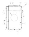
- FIG. 1 A device according to the invention for introducing and / or discharging air into / out of a / m has according to FIG. 1 a housing 1, which has a slot-shaped air outlet 2 and an air inlet indicated only by dashed lines.
- the embodiments according to the FIGS. 1 and 2 differ in that the air intake 3 after FIG. 1 is designed as an air inlet, while an air inlet 3.1 according to FIG. 2 is configured identically with the slot-shaped air outlet 2.
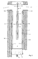
- the housing 1 is according to FIG. 2 from two shells 4.1 and 4.2, which together enclose an inner space 5.
- a deflection device 6 is used, which is designed plate-shaped. It consists of two panels 7.1 and 7.2, between which some heavy foil 8 and partially insulating strips 9 are inserted.
- the panels 7.1 and 7.2 are externally covered with a melanin resin layer 10.1 and 10.2.
- the interior 5 of the housing 1 is laterally also covered with a melamine resin layer 11.1 and 11.2, at the bottom there is a depth absorber 12, preferably also a melamine resin strip, which, however, is designed substantially thicker.
- the two shells 4.1 and 4.2 are identical.
- FIG. 1 can be seen that laterally in the shell 4.1 - and thus also in the shell 4.2 - circumferential flanges 13.1 to 13.4 are folded.
- the shell 4.1 is connected to corresponding flanges on the shell 4.2, wherein the flanges, unless the baffle 6 is disposed therebetween, separated by insulating strip 14 to each other.
- They are od by any configured fasteners 15, such as screws, rivets.
- These fasteners 15 are, for example, supported by a foam rubber seal or other elastic documents.
- the preparation of the inventive device is carried out in a simple manner by corresponding punching and folding of the shells 4.1 and 4.2 with the flanges 13.1 to 13.4. Since the shells are still open after manufacture, they can readily be covered with melanin resin layers 11.1 and 11.2.
- the deflection device 6 is produced separately, in which between the two panels 7.1 and 7.2, the heavy foil 8 and the corresponding insulating strips 9 are inserted.
- the deep absorber 12 When connecting the two shells 4.1 and 4.2, the deep absorber 12 is inserted in the interior 5 below, also the deflecting device 8 is inserted between the flanges 13.1, 13.2 and 13.3 and connected there with the flanges via the corresponding fastening means 15.
- both shells 4.1 and 4.2 are decoupled from each other by the insertion of the insulating strips 14 between the flanges so that one shell 4.1 can oscillate without affecting the other shell 4.2 thereof or vice versa.
- the plate-shaped deflection device 6 is preferably not covered with a melanin resin layer in the visible range of the air outlet 2 or air inlet 3 or 3.1, so that in this area the panel 7.1 or 7.2 can be colored with the same color as the air outlet or the air inlet , This offers the viewer a smooth, barely noticeable surface. This applies in particular to a white coloring of the shells 4.1 and 4.2 and the deflection device 6 in the field of vision.
- the device according to the invention is intended to be used in particular for lightweight walls with high acoustic requirements.
- FIG. 2 it can be seen that the housing 1 is inserted into a lightweight wall made of an inner and outer gypsum plasterboard wall 16.1 and 16.2.
- the housing 1 is supported against the plasterboard shells 16.1 and 16.2 via insulating strip 17, so that the housing 1 is decoupled from the lightweight wall.
- the air outlet 2 and also the air inlet 3.1 each comprise a surrounding frame 18.1 and 18.2.
- the air which now flows through the air inlet 3.1 into the interior 5, is deflected by the deflecting device 6 and damped by the melamine resin layers 10.2 and 11.2.
- the deep absorber 12 takes over the sound insulation of depth frequencies.
- a further insulation of the air bar is carried out by the melanine resin layers 10.1 and 11.1 when guiding the air in the direction of the air outlet 2.
- the inventive device is particularly suitable for installation in lightweight partition walls with particularly high demands on the Bauschalldämm Mass R'b 32 to 50 dB for single-shell partitions and 58 dB for two-shell partitions according to DIN 4109. Despite the excellent sound insulation, only a slight pressure loss is noted, which is particularly noteworthy.
- the device can still be provided with a corresponding fire protection equipment (F90 as an option).
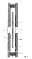
- the embodiment of the device according to the invention for introducing and / or discharging air according to FIG. 4 basically represents a doubling of the embodiment according to FIG. 2
- a housing Approximately in the middle of a round or slot-shaped air inlet 3.2 and a round or slot-shaped air outlet 2.1 is provided in a housing.
- This housing is in turn formed of two shells 4.3 and 4.4, which enclose an interior 5.1.
- a deflection 6.1 is attached, which is designed plate-shaped.
- This deflecting device 6.1 in turn separates the air inlet 3.2 from the air outlet 2.1 and is supported by the lateral flanges 13.1 and 13.3, which in FIG. 1 are recognizable.
- This overflow silencer has the advantage that a much higher volume flow can be promoted with low pressure drop.
- the volume flow is about twice as high as that in the device according to the FIGS. 1 and 2 ,
Landscapes
- Engineering & Computer Science (AREA)
- Chemical & Material Sciences (AREA)
- Combustion & Propulsion (AREA)
- Mechanical Engineering (AREA)
- General Engineering & Computer Science (AREA)
- Duct Arrangements (AREA)
- Building Environments (AREA)
- Air Humidification (AREA)
Description
- Die Erfindung betrifft eine Vorrichtung zum Ein- und/oder Ausbringen von Luft in/aus einen/m Raum mit einem Gehäuse, welche einen Lufteinlass und einen Luftauslass aufweist, wobei in einem Innenraum des Gehäuses eine Umlenkeinrichtung für die Luft vorgesehen ist.
- Derartige Vorrichtungen zur Führung von Luft bei klimatechnischen Anlagen sind in vielfältiger Form und Ausführung bekannt und auf dem Markt. Beispielsweise zeigt das Deutsche Gebrauchsmuster
73 22 128 eine schalldämmende Luftschleuse für Wohnräume od. dgl., die aus einem kanalartigen Gehäuse mit Ein- und Austrittsöffnungen für den durchzuleitenden Luftstrom besteht und werkstattmässig fertiggestellt wird. Die Luft verleiht im Innenraum dieser Luftschleuse eine Umlenkung und wird an Isolierschichten vorbeigeleitet, welche die Schalldämmung übernehmen. - Eine Vorrichtung der o. g. Art ist aus der
DE 42 32 315 A1 bekannt. Dort besteht die Zulufteinrichtung aus einem quaderförmigen Gehäuse, dass zum Einbau in Aussenwänden von Gebäuden und/oder Wohnungen vorgesehen ist. In dem Gehäuse befindet sich ein im Querschnitt etwa S-förmiger Luftumlenkkanal, welcher mit schall- und wärmedämmenden Material ausgekleidet ist, und durch welchen Luft von aussen ins Wohnungsinnere strömen kann. - Weiter ist in der
FR 2 523 190 - Aufgabe der vorliegenden Erfindung ist es, eine Vorrichtung zu schaffen, die hervorragende Dämmwerte aufweist und leicht herzustellen ist. Ferner soll ihre Stabilität wesentlich verbessert und ein Einbau in Leichtbauwände möglich sein.
- Zur Lösung der Aufgabe führen die Merkmale des Patentanspruchs 1.
- Die Herstellung des Gehäuses aus zwei Schalen hat den Vorteil, dass der Innenraum des Gehäuses mit den entsprechenden dämmenden Schichten belegt werden kann. Ferner ist eine separate Herstellung der Umlenkeinrichtung möglich, die erst nach ihrer Herstellung mit den beiden Schalen verbunden wird. Hierdurch können die beiden Schalen voneinander entkoppelt werden, so dass eine auf eine Schale einwirkende Schwingung keinerlei Auswirkungen auf die andere Schale hat. Ferner kann die Verbindung von Umlenkeinrichtung und Schalen so ausgestaltet sein, dass die Umlenkeinrichtung wesentlich zur Stabilität des gesamten Gehäuses beiträgt.
- Diesem Zweck dient vor allem, wenn von den Schalen Flansche abgekantet werden, die beim Zusammenbau flächig aneinander liegen können. Diese Flansche können dann durch Einlage von entsprechenden Isolierstreifen voneinander getrennt werden.
- Vor allem ist aber daran gedacht, dass die umlaufenden Flansche auch die plattenförmige Umlenkeinrichtung zwischen sich aufnehmen, so dass die plattenförmige Umlenkeinrichtung einer Verwindung der Schalen entgegenwirkt. Sie trägt wesentlich zur Stabilisierung des gesamten Gehäuses bei, so dass dieses immer seine gewünschte Form behält.
- Je nach dem zu fördernden Luftvolumen kann es ratsam sein, dass die Umlenkeinrichtung nur auf einer Seite von Luft umströmt wird. Soll mehr Luftvolumen gefördert werden, besteht die Möglichkeit, die Umlenkeinrichtung so in dem Innenraum des Gehäuses anzuordnen, dass an zwei oder auch an drei Seiten umströmt wird.
- Bevorzugt besteht die plattenförmige Umlenkeinrichtung aus zwei Tafeln, zwischen denen zumindest teilweise eine Isolation angeordnet ist. Diese Isolation kann unter anderem auch aus einer Schwerfolie bestehen. Dabei wird unter Schwerfolie eine Folie mit einem hohen Flächengewicht von bspw. 3 kg pro Quadratmeter verstanden.
- Die Umlenkeinrichtung soll zumindest teilweise mit einer Isolation belegt sein. Hier bietet sich der Einfachheit halber eine Melaninharzschicht, wobei jedoch auch andere schalldämmende Materialien denkbar sind.
- Ein besonderes Augenmerkmal ist darauf zu richten, dass die plattenförmige Umlenkeinrichtung jedoch im Sichtbereich von Lufteinlass bzw. Luftauslass bevorzugt nicht mit einer Isolation belegt ist, sondern dort mit der gleichen Farbe, bspw. weiss, beschichtet ist, wie der Lufteinlass bzw. Luftauslass. Heutzutage wünschen Architekten bspw. glatte, weisse Oberflächen zu sehen, auch im Innern einer Luftschleuse. Durch die erfindungsgemässe Umlenkeinrichtung wird ein best möglicher optischer Dichtschutz erwirkt. Ein Durchschauen oder Durchschimmern von Licht von einem Flur in Räume oder umgekehrt wird verhindert.
- Der Innenraum des Gehäuses selbst soll auch mit Isolation ausgekleidet sein. Auch hier bietet sich vor allem eine Melaninharzschicht an.
- In einem bevorzugten Ausführungsbeispiel der Erfindung ist am Boden des Innenraumes ein Tiefenabsorber für tiefe Frequenzen vorgesehen. Auch dieser kann aus einer Melaninharzschicht bestehen, die allerdings eine grössere Dicke aufweist.
- In einem bevorzugten Ausführungsbeispiel der Erfindung können beide Schalen identisch ausgebildet sein, so dass Lufteinlass und Luftauslass gleich sind und auch auf der gleichen Höhe liegen. Hierdurch werden die Herstellkosten reduziert.
- Zu einer Verbesserung der Schalldämmung trägt auch bei, wenn die Wandstärke der Schalen eine unterschiedliche Dicke aufweisen. In diesem Fall unterliegen die Schalen einer unterschiedlichen Schwingung, so dass eine Übertragung der Schwingungen aufeinander ausgeschlossen ist.
- Weitere Vorteile, Merkmale und Einzelheiten der Erfindung ergeben sich aus der nachfolgenden Beschreibung bevorzugter Ausführungsbeispiele sowie anhand der Zeichnung; diese zeigt in
- Figur 1
- eine Draufsicht auf eine erfindungsgemässe Vorrichtung zum Ein- und/oder Ausbringen von Luft in/aus einen/m Raum;
- Figur 2
- einen Längsschnitt durch die Vorrichtung gemäss
Figur 1 entlang Linie II-II in Gebrauchslage und in geringfügig abgeänderter Form; - Figur 3
- einen Längsschnitt durch ein weiteres Ausführungsbeispiel einer erfindungsgemässen Vorrichtung zum Ein- und/oder Ausbringen von Luft in/aus einen/m Raum.
- Eine erfindungsgemässe Vorrichtung zum Ein- und/oder Ausbringen von Luft in/aus einen/m weist gemäss
Figur 1 ein Gehäuse 1 auf, welches einen schlitzförmigen Luftauslass 2 und einen nur gestrichelt angedeuteten Lufteinlass besitzt. Die Ausführungsbeispiele gemäss denFiguren 1 und2 unterscheiden sich darin, dass der Lufteinlass 3 nachFigur 1 als Lufteinlassstutzen ausgebildet ist, während ein Lufteinlass 3.1 gemässFigur 2 identisch mit dem schlitzförmigen Luftauslass 2 ausgestaltet ist. - Das Gehäuse 1 besteht gemäss
Figur 2 aus zwei Schalen 4.1 und 4.2, welche zusammen einen Innenraum 5 umschliessen. In den Innenraum 5 ist eine Umlenkeinrichtung 6 eingesetzt, welche plattenförmig ausgestaltet ist. Sie besteht aus zwei Tafeln 7.1 und 7.2, zwischen denen teilweise eine Schwerfolie 8 und teilweise Isolierstreifen 9 eingelegt sind. Im Bereich des Innenraumes 5 sind die Tafeln 7.1 und 7.2 aussen mit einer Melaninharzschicht 10.1 und 10.2 belegt. - Der Innenraum 5 des Gehäuses 1 ist seitlich ebenfalls mit einer Melaninharzschicht 11.1 und 11.2 belegt, am Boden befindet sich ein Tiefenabsorber 12, bevorzugt ebenfalls ein Melaninharzstreifen, der jedoch wesentlich dicker ausgestaltet ist.
- In dem Ausführungsbeispiel gemäss
Figur 2 sind die beiden Schalen 4.1 und 4.2 identisch ausgebildet. InFigur 1 ist erkennbar, dass seitlich bei der Schale 4.1 - und damit auch bei der Schale 4.2 - umlaufenden Flansche 13.1 bis 13.4 abgekantet sind. Über diese Flansche 13.1 bis 13.4 ist die Schale 4.1 mit entsprechenden Flanschen an der Schale 4.2 verbunden, wobei die Flansche, soweit nicht die Umlenkeinrichtung 6 dazwischen angeordnet ist, getrennt durch Isolierstreifen 14 aneinander liegen. Sie sind durch beliebig ausgestaltete Befestigungsmittel 15, wie Schrauben, Nieten od. dgl. miteinander verbunden. Diese Befestigungsmittel 15 sind bspw. über eine Moosgummidichtung oder sonstige elastische Unterlagen abgestützt. - Die Herstellung der erfindungsgemässen Vorrichtung erfolgt auf einfache Art und Weise durch entsprechendes Ausstanzen und Abkanten der Schalen 4.1 und 4.2 mit den Flanschen 13.1 bis 13.4. Da die Schalen nach dem Herstellen noch offen sind, können sie ohne weiteres mit den Melaninharzschichten 11.1 und 11.2 belegt werden.
- Desgleichen wird die Umlenkeinrichtung 6 separat hergestellt, in dem zwischen die beiden Tafeln 7.1 und 7.2 die Schwerfolie 8 und die entsprechenden Isolierstreifen 9 eingelegt werden.
- Beim Verbinden der beiden Schalen 4.1 und 4.2 wird im Innenraum 5 unten der Tiefenabsorber 12 eingelegt, ferner wird die Umlenkeinrichtung 8 zwischen die Flansche 13.1, 13.2 und 13.3 eingesetzt und dort mit den Flanschen über die entsprechenden Befestigungsmittel 15 verbunden. Hierdurch erhält das Gehäuse 1 eine sehr grosse Steifigkeit, so dass eine gleichbleibende Form der Vorrichtung in jedem Fall gewährleistet ist, was bauseitig wünschenswert ist.
- Ferner werden beiden Schalen 4.1 und 4.2 durch das Einlegen der Isolierstreifen 14 zwischen die Flansche voneinander entkoppelt, so dass die eine Schale 4.1 schwingen kann, ohne die andere Schale 4.2 davon zu beeinflussen, bzw. umgekehrt.
- Die plattenförmige Umlenkeinrichtung 6 ist im Sichtbereich von Luftauslass 2 bzw. Lufteinlass 3 bzw. 3.1 bevorzugt nicht mit einer Melaninharzschicht belegt, so dass in diesem Bereich die Tafel 7.1 bzw. 7.2 mit der gleichen Farbe eingefärbt werden können, wie der Luftauslass bzw. der Lufteinlass. Hierdurch bietet sich dem Betrachter eine glatte, kaum auffallende Oberfläche. Dies gilt insbesondere bei einer weissen Einfärbung der Schalen 4.1 und 4.2 sowie der Umlenkeinrichtung 6 im Sichtbereich.
- Die erfindungsgemässe Vorrichtung soll vor allem bei Leichtbauwänden mit hohen akustischen Anforderungen Anwendung finden. In
Figur 2 ist erkennbar, dass das Gehäuse 1 in eine Leichtbauwand aus einer inneren und äusseren Gipskartunwandschale 16.1 und 16.2 eingesetzt ist. Das Gehäuse 1 stützt sich gegenüber den Gipskartonwandschalen 16.1 und 16.2 über Isolierstreifen 17 ab, so dass das Gehäuse 1 von der Leichtbauwand entkoppelt ist. Das gleiche gilt auch für den Lufteinlass 2 und den Lufteinlass 3.1, wobei hier die Isolierstreifen nicht näher gekennzeichnet sind. - Ferner umfasst aus optischen Gründen den Luftauslass 2 und auch den Lufteinlass 3.1 jeweils eine Umfassungszarge 18.1 und 18.2.
- Die Luft, die jetzt durch den Lufteinlass 3.1 in den Innenraum 5 einströmt, wird durch die Umlenkeinrichtung 6 umgelenkt und durch die Melaninharzschichten 10.2 und 11.2 gedämpft. Der Tiefenabsorber 12 übernimmt die Schalldämmung von Tiefenfrequenzen.
- Eine weitere Dämmung des Luftscheits erfolgt durch die Melaninharzschichten 10.1 und 11.1 bei der Führung der Luft in Richtung zum Luftauslass 2.
- Die erfindungsgemässe Vorrichtung ist vor allem zum Einbau in Leichtbautrennwände mit besonders hohen Anforderungen an das Bauschalldämm-Mass R'b 32 bis 50 dB für einschalige Trennwände sowie 58 dB für zweischalige Trennwände nach DIN 4109 geeignet. Trotz der hervorragenden Schalldämmung ist nur ein geringer Druckverlust zu vermerken, was besonders hervorzuheben ist.
- Zusätzlich kann die Vorrichtung noch mit einer entsprechenden Brandschutzausrüstung (F90 als Option) versehen werden.
- Das Ausführungsbeispiel der erfindungsgemässen Vorrichtung zum Ein-und/oder Ausbringen von Luft gemäss Figur 4 stellt im Grunde eine Verdoppelung des Ausführungsbeispiels gemäss
Figur 2 dar. Etwa in der Mitte ist ein runder oder schlitzförmiger Lufteinlass 3.2 und ein runder oder schlitzförmiger Luftauslass 2.1 in einem Gehäuse vorgesehen. Dieses Gehäuse wird wiederum aus zwei Schalen 4.3 und 4.4 gebildet, die einen Innenraum 5.1 umschliessen. In dem Innenraum 5.1 ist eine Umlenkeinrichtung 6.1 angesetzt, welche plattenförmig ausgestaltet ist. Diese Umlenkeinrichtung 6.1 trennt wiederum den Lufteinlass 3.2 von dem Luftauslass 2.1 und wird von den seitlichen Flanschen 13.1 und 13.3, die inFigur 1 erkennbar sind, gehalten. - Ansonsten ist lediglich noch vorgesehen, dass als Tiefenabsorber 12.1 eine Mineralwolle mit Vlies eingesetzt ist.
- Dieser Überström-Schalldämpfer hat den Vorteil, dass ein wesentlich höherer Volumenstrom bei geringem Druckverlust gefördert werden kann. Der Volumenstrom ist etwa doppelt so hoch, wie derjenige bei der Vorrichtung nach den
Figuren 1 und2 .
Claims (12)
- Vorrichtung zum Ein- und/oder Ausbringen von Luft in/aus einen/m Raum mit einem Gehäuse (1), welches einen Lufteinlass (3, 3.1, 3.2) und einen Luftauslass (2, 2.1) aufweist, wobei in einem Innenraum (5, 5.1) des Gehäuses (1) eine Umlenkeinrichtung (6, 6.1) für die Luft vorgesehen ist, wobei
das Gehäuse (1) aus zwei Schalen (4.1, 4.2, 4.3, 4.4) besteht, welche die plattenförmige Umlenkeinrichtung (6, 6.1) zwischen sich aufnehmen, wobei die Umlenkeinrichtung (6, 6.1) mit den beiden Schalen (4.1, 4.2, 4.3, 4.4) verbunden wird, dadurch gekennzeichnet, dass beim Verbinden der beiden Schalen (4.1, 4.2, 4.3, 4.4) die Umlenkeinrichtung (6, 6.1) zwischen Flansche (13.1, 13.2, 13.3) eingesetzt und dort mit den Flanschen (13.1, 13.2, 13.3) über Befestigungsmittel (15) verbunden ist. - Vorrichtung nach Anspruch 1, dadurch gekennzeichnet, dass die Umlenkeinrichtung (6) so in dem Innenraum (5) angeordnet ist, dass sie nur auf einer Seite von Luft umströmbar ist.
- Vorrichtung nach Anspruch 1, dadurch gekennzeichnet, dass die Umlenkeinrichtung (6.1) so im Innenraum (6.1) angeordnet ist, dass sie auf zumindest zwei Seiten von Luft umströmbar ist.
- Vorrichtung nach einem der Ansprüche 1 bis 3, dadurch gekennzeichnet, dass randseitig von den Schalen (4.1, 4.2, 4.3, 4.4) zumindest teilweise umlaufende Flansche (13.1 bis 13.4) abgekantet sind, welche der plattenförmigen Umlenkeinrichtung (6) zumindest teilweise anliegen.
- Vorrichtung nach Anspruch 4, dadurch gekennzeichnet, dass die plattenförmige Umlenkeinrichtung (6, 6.1) aus zwei Tafeln (7.1, 7.2) besteht, zwischen denen zumindest teilweise eine Isolation (8, 9) angeordnet ist.
- Vorrichtung nach Anspruch 5, dadurch gekennzeichnet, dass die Isolation zumindest teilweise aus einer Schwerfolie (8) besteht.
- Vorrichtung nach wenigstens einem der Ansprüche 1 bis 6, dadurch gekennzeichnet, dass die Umlenkeinrichtung (6, 6.1) teilweise mit einer Isolation, insbesondere mit einer Melaninharzschicht (10.1, 10.2) belegt ist.
- Vorrichtung nach wenigstens einem der Ansprüche 1 bis 7, dadurch gekennzeichnet, dass die Umlenkeinrichtung (6, 6.1) im Sichtbereich des Lufteinlasses (3, 3.1, 3.2) bzw. des Luftauslasses (2, 2.1) vorgesehen ist.
- Vorrichtung nach wenigstens einem der Ansprüche 1 bis 8, dadurch gekennzeichnet, dass der Innenraum (5, 5.1) des Gehäuses (1) zumindest teilweise mit einer Isolation, insbesondere mit einer Melaninharzschicht (11.1, 11.2) ausgekleidet ist.
- Vorrichtung nach Anspruch 9, dadurch gekennzeichnet, dass sich am Boden des Innenraumes (5, 5.1) ein Tiefenabsorber (12, 12.1) befindet.
- Vorrichtung nach wenigstens einem der Ansprüche 1 bis 10, dadurch gekennzeichnet, dass beide Schalen (4.1, 4.2, 4.3, 4.4) des Gehäuses (1) identisch ausgebildet sind.
- Vorrichtung nach wenigstens einem der Ansprüche 1 bis 11, dadurch gekennzeichnet, dass die Wandstärke der Schalen (4.1, 4.2) eine unterschiedliche Dicke aufweist.
Priority Applications (1)
| Application Number | Priority Date | Filing Date | Title |
|---|---|---|---|
| PL05007776T PL1589296T3 (pl) | 2004-04-19 | 2005-04-08 | Urządzenie do wtłaczania i/lub usuwania powietrza do/z pomieszczenia |
Applications Claiming Priority (4)
| Application Number | Priority Date | Filing Date | Title |
|---|---|---|---|
| DE200410019410 DE102004019410B3 (de) | 2004-04-19 | 2004-04-19 | Vorrichtung zum Ein- und/oder Ausbringen von Luft in/aus einen/m Raum |
| DE102004019410 | 2004-04-19 | ||
| DE102004040114 | 2004-08-18 | ||
| DE102004040114A DE102004040114A1 (de) | 2004-08-18 | 2004-08-18 | Vorrichtung zum Ein-und/oder Ausbringen von Luft in/aus einen/m Raum |
Publications (3)
| Publication Number | Publication Date |
|---|---|
| EP1589296A2 EP1589296A2 (de) | 2005-10-26 |
| EP1589296A3 EP1589296A3 (de) | 2007-06-20 |
| EP1589296B1 true EP1589296B1 (de) | 2013-07-03 |
Family
ID=34934921
Family Applications (1)
| Application Number | Title | Priority Date | Filing Date |
|---|---|---|---|
| EP05007776.7A Expired - Lifetime EP1589296B1 (de) | 2004-04-19 | 2005-04-08 | Vorrichtung zum Ein- und/oder Ausbringen von Luft in/aus einen/m Raum |
Country Status (5)
| Country | Link |
|---|---|
| EP (1) | EP1589296B1 (de) |
| DK (1) | DK1589296T3 (de) |
| ES (1) | ES2429533T3 (de) |
| PL (1) | PL1589296T3 (de) |
| PT (1) | PT1589296E (de) |
Families Citing this family (2)
| Publication number | Priority date | Publication date | Assignee | Title |
|---|---|---|---|---|
| EP4428464A1 (de) | 2023-03-07 | 2024-09-11 | Schako KG | Schalldämpfungsvorrichtung für eine belüftungsanlage |
| DE102024106314A1 (de) | 2023-03-07 | 2024-09-12 | SCHAKO KG Zweigniederlassung Kolbingen | Schalldämpfungsvorrichtung für eine Belüftungsanlage |
Family Cites Families (5)
| Publication number | Priority date | Publication date | Assignee | Title |
|---|---|---|---|---|
| DE7322128U (de) * | 1973-09-20 | Flamme W | Schalldämmende Luftschleuse für Wohnräume und dergl | |
| DD113806A1 (de) * | 1974-07-15 | 1975-06-20 | ||
| FR2523190A1 (fr) * | 1982-03-09 | 1983-09-16 | Cherrier Gerard | Bouche d'aeration acoustique |
| FI880799A7 (fi) * | 1988-02-19 | 1989-08-20 | Halton Oy | Luftfoerdelningsenhet. |
| CH691825A5 (de) * | 1997-01-31 | 2001-10-31 | Hesco Klima Schweiz Ag | Vorrichtung für die Luftzufuhr zu einem Gebäuderaum. |
-
2005
- 2005-04-08 ES ES05007776T patent/ES2429533T3/es not_active Expired - Lifetime
- 2005-04-08 PT PT50077767T patent/PT1589296E/pt unknown
- 2005-04-08 EP EP05007776.7A patent/EP1589296B1/de not_active Expired - Lifetime
- 2005-04-08 PL PL05007776T patent/PL1589296T3/pl unknown
- 2005-04-08 DK DK05007776.7T patent/DK1589296T3/da active
Also Published As
| Publication number | Publication date |
|---|---|
| PT1589296E (pt) | 2013-09-30 |
| EP1589296A2 (de) | 2005-10-26 |
| ES2429533T3 (es) | 2013-11-15 |
| EP1589296A3 (de) | 2007-06-20 |
| DK1589296T3 (da) | 2013-09-30 |
| PL1589296T3 (pl) | 2013-12-31 |
Similar Documents
| Publication | Publication Date | Title |
|---|---|---|
| DE202008018286U1 (de) | Luftauslass | |
| DE1196877B (de) | Bauelement nach dem Resonatorprinzip zur Erstellung von schalldaempfenden Flaechen oder Kanaelen | |
| EP3705802A1 (de) | Schalldämmanordnung | |
| AT520393B1 (de) | Schallabsorptionselement | |
| EP1589296B1 (de) | Vorrichtung zum Ein- und/oder Ausbringen von Luft in/aus einen/m Raum | |
| DE2410170A1 (de) | Schallschlucklueftung | |
| DE102004019410B3 (de) | Vorrichtung zum Ein- und/oder Ausbringen von Luft in/aus einen/m Raum | |
| DE102004040114A1 (de) | Vorrichtung zum Ein-und/oder Ausbringen von Luft in/aus einen/m Raum | |
| DE102012204503B4 (de) | Lampenband für einen Fahrgastinnenraum eines Schienenfahrzeugs | |
| DE202012003817U1 (de) | Fertigteilsystem für ein Raum-in-Raum-System | |
| DE202021106433U1 (de) | Türblatt mit Überströmfunktion | |
| DE202017100927U1 (de) | Schalldämmeinsatz für dezentrale Wohnraumbelüftungsanlagen oder Außenluftdurchlasssysteme | |
| EP3085846A1 (de) | Überströmelement und wandelement | |
| EP2489810B1 (de) | Deckenelement aus zwei gelochten Gipskartonplatten mit dazwischenliegenden Rohrleitungen als Heiz-/Kühldecke | |
| EP1876308B1 (de) | Schallabsorbierende Vorrichtung | |
| DE102004019409A1 (de) | Vorrichtung zum Ein- und/oder Ausbringen von luft in/aus einen/m Raum | |
| DE202012008029U1 (de) | Lüftungsrohr - Bauelement mit verbesserter Schallabsorption sowie Außenwandluftdurchlass | |
| DE202010009659U1 (de) | Schallschutzsystem | |
| DE202011105663U1 (de) | Dämmplattenanordnung, insbesondere Stufen-Dämmplatte, und Dämmvorrichtung | |
| DE102021116126B4 (de) | Lüftungsrohr-Einsatz | |
| DE2442378A1 (de) | Klimaanlage | |
| DE202011002963U1 (de) | Absorbermodul und Rauminstallation | |
| DE102010020989A1 (de) | Einbruchhemmende Wand | |
| DE102017005624A1 (de) | Mauerdurchführungsrohr | |
| AT338316B (de) | Schalldampfer |
Legal Events
| Date | Code | Title | Description |
|---|---|---|---|
| PUAI | Public reference made under article 153(3) epc to a published international application that has entered the european phase |
Free format text: ORIGINAL CODE: 0009012 |
|
| AK | Designated contracting states |
Kind code of ref document: A2 Designated state(s): AT BE BG CH CY CZ DE DK EE ES FI FR GB GR HU IE IS IT LI LT LU MC NL PL PT RO SE SI SK TR |
|
| AX | Request for extension of the european patent |
Extension state: AL BA HR LV MK YU |
|
| PUAL | Search report despatched |
Free format text: ORIGINAL CODE: 0009013 |
|
| AK | Designated contracting states |
Kind code of ref document: A3 Designated state(s): AT BE BG CH CY CZ DE DK EE ES FI FR GB GR HU IE IS IT LI LT LU MC NL PL PT RO SE SI SK TR |
|
| AX | Request for extension of the european patent |
Extension state: AL BA HR LV MK YU |
|
| 17P | Request for examination filed |
Effective date: 20071218 |
|
| AKX | Designation fees paid |
Designated state(s): AT BE BG CH CY CZ DE DK EE ES FI FR GB GR HU IE IS IT LI LT LU MC NL PL PT RO SE SI SK TR |
|
| 17Q | First examination report despatched |
Effective date: 20100927 |
|
| REG | Reference to a national code |
Ref country code: DE Ref legal event code: R079 Ref document number: 502005013801 Country of ref document: DE Free format text: PREVIOUS MAIN CLASS: F24F0013240000 Ipc: F24F0013060000 |
|
| RIC1 | Information provided on ipc code assigned before grant |
Ipc: F24F 13/18 20060101ALI20121211BHEP Ipc: F24F 13/24 20060101ALI20121211BHEP Ipc: F24F 13/06 20060101AFI20121211BHEP |
|
| GRAP | Despatch of communication of intention to grant a patent |
Free format text: ORIGINAL CODE: EPIDOSNIGR1 |
|
| GRAS | Grant fee paid |
Free format text: ORIGINAL CODE: EPIDOSNIGR3 |
|
| GRAA | (expected) grant |
Free format text: ORIGINAL CODE: 0009210 |
|
| AK | Designated contracting states |
Kind code of ref document: B1 Designated state(s): AT BE BG CH CY CZ DE DK EE ES FI FR GB GR HU IE IS IT LI LT LU MC NL PL PT RO SE SI SK TR |
|
| REG | Reference to a national code |
Ref country code: GB Ref legal event code: FG4D Free format text: NOT ENGLISH |
|
| REG | Reference to a national code |
Ref country code: CH Ref legal event code: EP Ref country code: AT Ref legal event code: REF Ref document number: 620008 Country of ref document: AT Kind code of ref document: T Effective date: 20130715 |
|
| REG | Reference to a national code |
Ref country code: IE Ref legal event code: FG4D Free format text: LANGUAGE OF EP DOCUMENT: GERMAN Ref country code: CH Ref legal event code: NV Representative=s name: ARIE WUBBEN C/O ALTAMURA GMBH, CH |
|
| REG | Reference to a national code |
Ref country code: DE Ref legal event code: R096 Ref document number: 502005013801 Country of ref document: DE Effective date: 20130829 |
|
| REG | Reference to a national code |
Ref country code: DK Ref legal event code: T3 Effective date: 20130926 Ref country code: DK Ref legal event code: T3 Ref country code: PT Ref legal event code: SC4A Free format text: AVAILABILITY OF NATIONAL TRANSLATION Effective date: 20130919 |
|
| REG | Reference to a national code |
Ref country code: RO Ref legal event code: EPE |
|
| PG25 | Lapsed in a contracting state [announced via postgrant information from national office to epo] |
Ref country code: SI Free format text: LAPSE BECAUSE OF FAILURE TO SUBMIT A TRANSLATION OF THE DESCRIPTION OR TO PAY THE FEE WITHIN THE PRESCRIBED TIME-LIMIT Effective date: 20130703 |
|
| REG | Reference to a national code |
Ref country code: NL Ref legal event code: T3 |
|
| REG | Reference to a national code |
Ref country code: ES Ref legal event code: FG2A Ref document number: 2429533 Country of ref document: ES Kind code of ref document: T3 Effective date: 20131115 |
|
| REG | Reference to a national code |
Ref country code: LT Ref legal event code: MG4D |
|
| REG | Reference to a national code |
Ref country code: PL Ref legal event code: T3 |
|
| PG25 | Lapsed in a contracting state [announced via postgrant information from national office to epo] |
Ref country code: IS Free format text: LAPSE BECAUSE OF FAILURE TO SUBMIT A TRANSLATION OF THE DESCRIPTION OR TO PAY THE FEE WITHIN THE PRESCRIBED TIME-LIMIT Effective date: 20131103 Ref country code: CY Free format text: LAPSE BECAUSE OF FAILURE TO SUBMIT A TRANSLATION OF THE DESCRIPTION OR TO PAY THE FEE WITHIN THE PRESCRIBED TIME-LIMIT Effective date: 20130619 Ref country code: LT Free format text: LAPSE BECAUSE OF FAILURE TO SUBMIT A TRANSLATION OF THE DESCRIPTION OR TO PAY THE FEE WITHIN THE PRESCRIBED TIME-LIMIT Effective date: 20130703 Ref country code: SE Free format text: LAPSE BECAUSE OF FAILURE TO SUBMIT A TRANSLATION OF THE DESCRIPTION OR TO PAY THE FEE WITHIN THE PRESCRIBED TIME-LIMIT Effective date: 20130703 |
|
| REG | Reference to a national code |
Ref country code: SK Ref legal event code: T3 Ref document number: E 15221 Country of ref document: SK |
|
| PG25 | Lapsed in a contracting state [announced via postgrant information from national office to epo] |
Ref country code: FI Free format text: LAPSE BECAUSE OF FAILURE TO SUBMIT A TRANSLATION OF THE DESCRIPTION OR TO PAY THE FEE WITHIN THE PRESCRIBED TIME-LIMIT Effective date: 20130703 Ref country code: GR Free format text: LAPSE BECAUSE OF FAILURE TO SUBMIT A TRANSLATION OF THE DESCRIPTION OR TO PAY THE FEE WITHIN THE PRESCRIBED TIME-LIMIT Effective date: 20131004 |
|
| PG25 | Lapsed in a contracting state [announced via postgrant information from national office to epo] |
Ref country code: CY Free format text: LAPSE BECAUSE OF FAILURE TO SUBMIT A TRANSLATION OF THE DESCRIPTION OR TO PAY THE FEE WITHIN THE PRESCRIBED TIME-LIMIT Effective date: 20130703 |
|
| PG25 | Lapsed in a contracting state [announced via postgrant information from national office to epo] |
Ref country code: EE Free format text: LAPSE BECAUSE OF FAILURE TO SUBMIT A TRANSLATION OF THE DESCRIPTION OR TO PAY THE FEE WITHIN THE PRESCRIBED TIME-LIMIT Effective date: 20130703 |
|
| PLBE | No opposition filed within time limit |
Free format text: ORIGINAL CODE: 0009261 |
|
| STAA | Information on the status of an ep patent application or granted ep patent |
Free format text: STATUS: NO OPPOSITION FILED WITHIN TIME LIMIT |
|
| 26N | No opposition filed |
Effective date: 20140404 |
|
| REG | Reference to a national code |
Ref country code: HU Ref legal event code: AG4A Ref document number: E019606 Country of ref document: HU |
|
| REG | Reference to a national code |
Ref country code: DE Ref legal event code: R097 Ref document number: 502005013801 Country of ref document: DE Effective date: 20140404 |
|
| PG25 | Lapsed in a contracting state [announced via postgrant information from national office to epo] |
Ref country code: MC Free format text: LAPSE BECAUSE OF FAILURE TO SUBMIT A TRANSLATION OF THE DESCRIPTION OR TO PAY THE FEE WITHIN THE PRESCRIBED TIME-LIMIT Effective date: 20130703 |
|
| REG | Reference to a national code |
Ref country code: IE Ref legal event code: MM4A |
|
| PG25 | Lapsed in a contracting state [announced via postgrant information from national office to epo] |
Ref country code: IE Free format text: LAPSE BECAUSE OF NON-PAYMENT OF DUE FEES Effective date: 20140408 |
|
| REG | Reference to a national code |
Ref country code: DE Ref legal event code: R082 Ref document number: 502005013801 Country of ref document: DE Representative=s name: PATENTANWAELTE UND RECHTSANWALT DR. WEISS, ARA, DE Ref country code: DE Ref legal event code: R082 Ref document number: 502005013801 Country of ref document: DE Representative=s name: PATENTANWAELTE UND RECHTSANWALT WEISS, ARAT & , DE |
|
| REG | Reference to a national code |
Ref country code: CH Ref legal event code: PCAR Free format text: NEW ADDRESS: MUEHLENTALSTRASSE 186, 8200 SCHAFFHAUSEN (CH) |
|
| REG | Reference to a national code |
Ref country code: FR Ref legal event code: PLFP Year of fee payment: 12 |
|
| PG25 | Lapsed in a contracting state [announced via postgrant information from national office to epo] |
Ref country code: BG Free format text: LAPSE BECAUSE OF FAILURE TO SUBMIT A TRANSLATION OF THE DESCRIPTION OR TO PAY THE FEE WITHIN THE PRESCRIBED TIME-LIMIT Effective date: 20130703 |
|
| PGFP | Annual fee paid to national office [announced via postgrant information from national office to epo] |
Ref country code: PT Payment date: 20160408 Year of fee payment: 12 Ref country code: TR Payment date: 20160408 Year of fee payment: 12 Ref country code: RO Payment date: 20160411 Year of fee payment: 12 |
|
| PGFP | Annual fee paid to national office [announced via postgrant information from national office to epo] |
Ref country code: SK Payment date: 20161006 Year of fee payment: 12 |
|
| REG | Reference to a national code |
Ref country code: FR Ref legal event code: PLFP Year of fee payment: 13 |
|
| PGFP | Annual fee paid to national office [announced via postgrant information from national office to epo] |
Ref country code: NL Payment date: 20170419 Year of fee payment: 13 |
|
| PGFP | Annual fee paid to national office [announced via postgrant information from national office to epo] |
Ref country code: DK Payment date: 20170419 Year of fee payment: 13 |
|
| PGFP | Annual fee paid to national office [announced via postgrant information from national office to epo] |
Ref country code: BE Payment date: 20170419 Year of fee payment: 13 |
|
| REG | Reference to a national code |
Ref country code: SK Ref legal event code: MM4A Ref document number: E 15221 Country of ref document: SK Effective date: 20170408 |
|
| PG25 | Lapsed in a contracting state [announced via postgrant information from national office to epo] |
Ref country code: RO Free format text: LAPSE BECAUSE OF NON-PAYMENT OF DUE FEES Effective date: 20170408 Ref country code: SK Free format text: LAPSE BECAUSE OF NON-PAYMENT OF DUE FEES Effective date: 20170408 |
|
| PG25 | Lapsed in a contracting state [announced via postgrant information from national office to epo] |
Ref country code: PT Free format text: LAPSE BECAUSE OF NON-PAYMENT OF DUE FEES Effective date: 20171009 |
|
| REG | Reference to a national code |
Ref country code: FR Ref legal event code: PLFP Year of fee payment: 14 |
|
| REG | Reference to a national code |
Ref country code: DK Ref legal event code: EBP Effective date: 20180430 |
|
| PG25 | Lapsed in a contracting state [announced via postgrant information from national office to epo] |
Ref country code: CZ Free format text: LAPSE BECAUSE OF NON-PAYMENT OF DUE FEES Effective date: 20180408 |
|
| REG | Reference to a national code |
Ref country code: NL Ref legal event code: MM Effective date: 20180501 |
|
| REG | Reference to a national code |
Ref country code: BE Ref legal event code: MM Effective date: 20180430 |
|
| PG25 | Lapsed in a contracting state [announced via postgrant information from national office to epo] |
Ref country code: NL Free format text: LAPSE BECAUSE OF NON-PAYMENT OF DUE FEES Effective date: 20180501 |
|
| PG25 | Lapsed in a contracting state [announced via postgrant information from national office to epo] |
Ref country code: BE Free format text: LAPSE BECAUSE OF NON-PAYMENT OF DUE FEES Effective date: 20180430 |
|
| PG25 | Lapsed in a contracting state [announced via postgrant information from national office to epo] |
Ref country code: DK Free format text: LAPSE BECAUSE OF NON-PAYMENT OF DUE FEES Effective date: 20180430 |
|
| PG25 | Lapsed in a contracting state [announced via postgrant information from national office to epo] |
Ref country code: TR Free format text: LAPSE BECAUSE OF NON-PAYMENT OF DUE FEES Effective date: 20170408 |
|
| REG | Reference to a national code |
Ref country code: DE Ref legal event code: R081 Ref document number: 502005013801 Country of ref document: DE Owner name: SCHAKO KG, DE Free format text: FORMER OWNER: SCHAKO KLIMA LUFT FERDINAND SCHAD KG, 78600 KOLBINGEN, DE |
|
| REG | Reference to a national code |
Ref country code: HU Ref legal event code: GB9C Owner name: SCHAKO KG, DE Free format text: FORMER OWNER(S): SCHAKO KLIMA LUFT FERDINAND SCHAD KG, DE Ref country code: HU Ref legal event code: FH1C Free format text: FORMER REPRESENTATIVE(S): ERDELY PETER - DANUBIA SZABADALMI ES JOGI IRODA KFT., HU Representative=s name: DANUBIA SZABADALMI ES JOGI IRODA KFT., HU |
|
| PGFP | Annual fee paid to national office [announced via postgrant information from national office to epo] |
Ref country code: PL Payment date: 20230327 Year of fee payment: 19 |
|
| REG | Reference to a national code |
Ref country code: GB Ref legal event code: 732E Free format text: REGISTERED BETWEEN 20230602 AND 20230607 |
|
| PGFP | Annual fee paid to national office [announced via postgrant information from national office to epo] |
Ref country code: LU Payment date: 20230417 Year of fee payment: 19 |
|
| PGFP | Annual fee paid to national office [announced via postgrant information from national office to epo] |
Ref country code: IT Payment date: 20230428 Year of fee payment: 19 Ref country code: FR Payment date: 20230417 Year of fee payment: 19 |
|
| PGFP | Annual fee paid to national office [announced via postgrant information from national office to epo] |
Ref country code: HU Payment date: 20230330 Year of fee payment: 19 |
|
| PGFP | Annual fee paid to national office [announced via postgrant information from national office to epo] |
Ref country code: GB Payment date: 20230420 Year of fee payment: 19 |
|
| REG | Reference to a national code |
Ref country code: AT Ref legal event code: PC Ref document number: 620008 Country of ref document: AT Kind code of ref document: T Owner name: SCHAKO KG, DE Effective date: 20240122 |
|
| REG | Reference to a national code |
Ref country code: ES Ref legal event code: PC2A Owner name: SCHAKO KG Effective date: 20240416 |
|
| PGFP | Annual fee paid to national office [announced via postgrant information from national office to epo] |
Ref country code: DE Payment date: 20240627 Year of fee payment: 20 |
|
| PGFP | Annual fee paid to national office [announced via postgrant information from national office to epo] |
Ref country code: CH Payment date: 20240515 Year of fee payment: 20 |
|
| PGFP | Annual fee paid to national office [announced via postgrant information from national office to epo] |
Ref country code: ES Payment date: 20240517 Year of fee payment: 20 |
|
| PGFP | Annual fee paid to national office [announced via postgrant information from national office to epo] |
Ref country code: AT Payment date: 20240426 Year of fee payment: 20 |
|
| PG25 | Lapsed in a contracting state [announced via postgrant information from national office to epo] |
Ref country code: LU Free format text: LAPSE BECAUSE OF NON-PAYMENT OF DUE FEES Effective date: 20240408 |
|
| GBPC | Gb: european patent ceased through non-payment of renewal fee |
Effective date: 20240408 |
|
| PG25 | Lapsed in a contracting state [announced via postgrant information from national office to epo] |
Ref country code: LU Free format text: LAPSE BECAUSE OF NON-PAYMENT OF DUE FEES Effective date: 20240408 |
|
| PG25 | Lapsed in a contracting state [announced via postgrant information from national office to epo] |
Ref country code: HU Free format text: LAPSE BECAUSE OF NON-PAYMENT OF DUE FEES Effective date: 20240409 |
|
| PG25 | Lapsed in a contracting state [announced via postgrant information from national office to epo] |
Ref country code: GB Free format text: LAPSE BECAUSE OF NON-PAYMENT OF DUE FEES Effective date: 20240408 |
|
| PG25 | Lapsed in a contracting state [announced via postgrant information from national office to epo] |
Ref country code: FR Free format text: LAPSE BECAUSE OF NON-PAYMENT OF DUE FEES Effective date: 20240430 |
|
| PG25 | Lapsed in a contracting state [announced via postgrant information from national office to epo] |
Ref country code: HU Free format text: LAPSE BECAUSE OF NON-PAYMENT OF DUE FEES Effective date: 20240409 Ref country code: GB Free format text: LAPSE BECAUSE OF NON-PAYMENT OF DUE FEES Effective date: 20240408 Ref country code: FR Free format text: LAPSE BECAUSE OF NON-PAYMENT OF DUE FEES Effective date: 20240430 |
|
| REG | Reference to a national code |
Ref country code: DE Ref legal event code: R071 Ref document number: 502005013801 Country of ref document: DE |
|
| REG | Reference to a national code |
Ref country code: CH Ref legal event code: PL |
|
| REG | Reference to a national code |
Ref country code: ES Ref legal event code: FD2A Effective date: 20250425 |
|
| PG25 | Lapsed in a contracting state [announced via postgrant information from national office to epo] |
Ref country code: IT Free format text: LAPSE BECAUSE OF NON-PAYMENT OF DUE FEES Effective date: 20240408 |
|
| REG | Reference to a national code |
Ref country code: AT Ref legal event code: MK07 Ref document number: 620008 Country of ref document: AT Kind code of ref document: T Effective date: 20250408 |
|
| PG25 | Lapsed in a contracting state [announced via postgrant information from national office to epo] |
Ref country code: PL Free format text: LAPSE BECAUSE OF NON-PAYMENT OF DUE FEES Effective date: 20240408 |
|
| PG25 | Lapsed in a contracting state [announced via postgrant information from national office to epo] |
Ref country code: ES Free format text: LAPSE BECAUSE OF EXPIRATION OF PROTECTION Effective date: 20250409 |