EP1589282B1 - Dünne, plattenförmige Kraftfahrzeugleuchte - Google Patents
Dünne, plattenförmige Kraftfahrzeugleuchte Download PDFInfo
- Publication number
- EP1589282B1 EP1589282B1 EP04425280A EP04425280A EP1589282B1 EP 1589282 B1 EP1589282 B1 EP 1589282B1 EP 04425280 A EP04425280 A EP 04425280A EP 04425280 A EP04425280 A EP 04425280A EP 1589282 B1 EP1589282 B1 EP 1589282B1
- Authority
- EP
- European Patent Office
- Prior art keywords
- source
- light
- section
- primary reflector
- reflecting
- Prior art date
- Legal status (The legal status is an assumption and is not a legal conclusion. Google has not performed a legal analysis and makes no representation as to the accuracy of the status listed.)
- Expired - Lifetime
Links
- 230000002093 peripheral effect Effects 0.000 claims abstract description 5
- 238000000576 coating method Methods 0.000 claims description 6
- 238000004040 coloring Methods 0.000 claims 1
- 239000002184 metal Substances 0.000 claims 1
- 239000011248 coating agent Substances 0.000 description 4
- 230000003287 optical effect Effects 0.000 description 2
- 238000004088 simulation Methods 0.000 description 2
- 238000010276 construction Methods 0.000 description 1
- 230000000694 effects Effects 0.000 description 1
- 239000000463 material Substances 0.000 description 1
- 238000000034 method Methods 0.000 description 1
- 238000005457 optimization Methods 0.000 description 1
- 229920002994 synthetic fiber Polymers 0.000 description 1
Images


Classifications
-
- F—MECHANICAL ENGINEERING; LIGHTING; HEATING; WEAPONS; BLASTING
- F21—LIGHTING
- F21V—FUNCTIONAL FEATURES OR DETAILS OF LIGHTING DEVICES OR SYSTEMS THEREOF; STRUCTURAL COMBINATIONS OF LIGHTING DEVICES WITH OTHER ARTICLES, NOT OTHERWISE PROVIDED FOR
- F21V7/00—Reflectors for light sources
- F21V7/0091—Reflectors for light sources using total internal reflection
-
- F—MECHANICAL ENGINEERING; LIGHTING; HEATING; WEAPONS; BLASTING
- F21—LIGHTING
- F21S—NON-PORTABLE LIGHTING DEVICES; SYSTEMS THEREOF; VEHICLE LIGHTING DEVICES SPECIALLY ADAPTED FOR VEHICLE EXTERIORS
- F21S41/00—Illuminating devices specially adapted for vehicle exteriors, e.g. headlamps
- F21S41/10—Illuminating devices specially adapted for vehicle exteriors, e.g. headlamps characterised by the light source
- F21S41/14—Illuminating devices specially adapted for vehicle exteriors, e.g. headlamps characterised by the light source characterised by the type of light source
- F21S41/141—Light emitting diodes [LED]
- F21S41/143—Light emitting diodes [LED] the main emission direction of the LED being parallel to the optical axis of the illuminating device
-
- F—MECHANICAL ENGINEERING; LIGHTING; HEATING; WEAPONS; BLASTING
- F21—LIGHTING
- F21S—NON-PORTABLE LIGHTING DEVICES; SYSTEMS THEREOF; VEHICLE LIGHTING DEVICES SPECIALLY ADAPTED FOR VEHICLE EXTERIORS
- F21S41/00—Illuminating devices specially adapted for vehicle exteriors, e.g. headlamps
- F21S41/10—Illuminating devices specially adapted for vehicle exteriors, e.g. headlamps characterised by the light source
- F21S41/14—Illuminating devices specially adapted for vehicle exteriors, e.g. headlamps characterised by the light source characterised by the type of light source
- F21S41/141—Light emitting diodes [LED]
- F21S41/151—Light emitting diodes [LED] arranged in one or more lines
- F21S41/153—Light emitting diodes [LED] arranged in one or more lines arranged in a matrix
-
- F—MECHANICAL ENGINEERING; LIGHTING; HEATING; WEAPONS; BLASTING
- F21—LIGHTING
- F21S—NON-PORTABLE LIGHTING DEVICES; SYSTEMS THEREOF; VEHICLE LIGHTING DEVICES SPECIALLY ADAPTED FOR VEHICLE EXTERIORS
- F21S41/00—Illuminating devices specially adapted for vehicle exteriors, e.g. headlamps
- F21S41/20—Illuminating devices specially adapted for vehicle exteriors, e.g. headlamps characterised by refractors, transparent cover plates, light guides or filters
- F21S41/24—Light guides
-
- F—MECHANICAL ENGINEERING; LIGHTING; HEATING; WEAPONS; BLASTING
- F21—LIGHTING
- F21S—NON-PORTABLE LIGHTING DEVICES; SYSTEMS THEREOF; VEHICLE LIGHTING DEVICES SPECIALLY ADAPTED FOR VEHICLE EXTERIORS
- F21S43/00—Signalling devices specially adapted for vehicle exteriors, e.g. brake lamps, direction indicator lights or reversing lights
- F21S43/20—Signalling devices specially adapted for vehicle exteriors, e.g. brake lamps, direction indicator lights or reversing lights characterised by refractors, transparent cover plates, light guides or filters
- F21S43/235—Light guides
- F21S43/236—Light guides characterised by the shape of the light guide
- F21S43/241—Light guides characterised by the shape of the light guide of complex shape
-
- F—MECHANICAL ENGINEERING; LIGHTING; HEATING; WEAPONS; BLASTING
- F21—LIGHTING
- F21S—NON-PORTABLE LIGHTING DEVICES; SYSTEMS THEREOF; VEHICLE LIGHTING DEVICES SPECIALLY ADAPTED FOR VEHICLE EXTERIORS
- F21S43/00—Signalling devices specially adapted for vehicle exteriors, e.g. brake lamps, direction indicator lights or reversing lights
- F21S43/20—Signalling devices specially adapted for vehicle exteriors, e.g. brake lamps, direction indicator lights or reversing lights characterised by refractors, transparent cover plates, light guides or filters
- F21S43/235—Light guides
- F21S43/242—Light guides characterised by the emission area
- F21S43/243—Light guides characterised by the emission area emitting light from one or more of its extremities
-
- F—MECHANICAL ENGINEERING; LIGHTING; HEATING; WEAPONS; BLASTING
- F21—LIGHTING
- F21S—NON-PORTABLE LIGHTING DEVICES; SYSTEMS THEREOF; VEHICLE LIGHTING DEVICES SPECIALLY ADAPTED FOR VEHICLE EXTERIORS
- F21S43/00—Signalling devices specially adapted for vehicle exteriors, e.g. brake lamps, direction indicator lights or reversing lights
- F21S43/20—Signalling devices specially adapted for vehicle exteriors, e.g. brake lamps, direction indicator lights or reversing lights characterised by refractors, transparent cover plates, light guides or filters
- F21S43/235—Light guides
- F21S43/249—Light guides with two or more light sources being coupled into the light guide
-
- F—MECHANICAL ENGINEERING; LIGHTING; HEATING; WEAPONS; BLASTING
- F21—LIGHTING
- F21S—NON-PORTABLE LIGHTING DEVICES; SYSTEMS THEREOF; VEHICLE LIGHTING DEVICES SPECIALLY ADAPTED FOR VEHICLE EXTERIORS
- F21S43/00—Signalling devices specially adapted for vehicle exteriors, e.g. brake lamps, direction indicator lights or reversing lights
- F21S43/30—Signalling devices specially adapted for vehicle exteriors, e.g. brake lamps, direction indicator lights or reversing lights characterised by reflectors
- F21S43/31—Optical layout thereof
- F21S43/315—Optical layout thereof using total internal reflection
-
- F—MECHANICAL ENGINEERING; LIGHTING; HEATING; WEAPONS; BLASTING
- F21—LIGHTING
- F21V—FUNCTIONAL FEATURES OR DETAILS OF LIGHTING DEVICES OR SYSTEMS THEREOF; STRUCTURAL COMBINATIONS OF LIGHTING DEVICES WITH OTHER ARTICLES, NOT OTHERWISE PROVIDED FOR
- F21V7/00—Reflectors for light sources
- F21V7/0008—Reflectors for light sources providing for indirect lighting
-
- F—MECHANICAL ENGINEERING; LIGHTING; HEATING; WEAPONS; BLASTING
- F21—LIGHTING
- F21Y—INDEXING SCHEME ASSOCIATED WITH SUBCLASSES F21K, F21L, F21S and F21V, RELATING TO THE FORM OR THE KIND OF THE LIGHT SOURCES OR OF THE COLOUR OF THE LIGHT EMITTED
- F21Y2115/00—Light-generating elements of semiconductor light sources
- F21Y2115/10—Light-emitting diodes [LED]
Definitions
- the present invention relates to the field of lighting systems, and in particular lights for motor vehicles, of the type comprising one or more elementary cells, each including: a transparent dielectric module in the form of a plate, with two opposite main faces; a substantially point-like source set in the proximity of a first one of the two main faces of said module; a primary reflector formed on the second of the main faces of the module for reflecting a first time the light coming from the source that has traversed the plate; and a secondary reflector formed on the first main face of said module, for reflecting a second time the light already reflected by the primary reflector and directing it towards the outside of the module, on the side of said second main face, so as to collimate it in a pre-determined direction.
- a lighting system of the type specified above has already been proposed by the present applicant in the European patent No. EP 0 766 115 B1 and in the corresponding U.S. patent No. US 5 841 596, as likewise in the European patent No. EP 0 767 393 B1 and in the corresponding U.S. patent No. US 5 884 995 .
- the individual collimation cell operates in a mode similar to a telescope of the Cassegrain type.
- a point-like light source 1 is located in the proximity of a first face I of a transparent plate 2 made of plastic material.
- the light emitted by the source 1 is coupled within the plate 2 through a transparent portion of said face I, impinges upon a primary reflector 3 set on the second face II of the transparent portion and generally obtained by coating a portion of said face II with a reflecting layer, and is reflected by said primary reflector 3 towards a secondary reflector 4 set on the face I about said transparent portion and generally obtained by coating a portion of said face I with a reflecting layer.
- the light is again reflected by the secondary reflector 4 towards the face II and exits from the plate through a transparent portion of said face II, undergoing a refraction.
- the primary reflector 3 and secondary reflector 4 have shapes which are designed for producing in combination a collimation of the beam emitted by the point-like source 1.
- the point-like source 1 can be located in a position corresponding to the transparent portion of the face 1 and possibly englobed in the plate in a position corresponding to said transparent portion.
- the purpose of the present invention is to improve the performance of the optical system proposed previously by increasing control of the light distribution and hence the value of intensity in a pre-determined direction.
- the primary reflector A is radiused to the transparent portion B with a continuous profile and with a continuous curvature, so that the portions C and D of the secondary reflector operate in a substantially exclusive way on the rays reflected by the primary reflector A and by the transparent portion B of the face II, respectively.
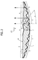
- Figure 2 is a cross-sectional view of a first embodiment of the collimator which does not form part of the present invention, in a plane of cross section perpendicular to the plate.
- the parts corresponding to those of Figure 1 are designated by the same reference numbers.
- the point-like light source typically a chip-LED
- the plate, made of synthetic material, is designated by 2, and I and II designate the two main faces of the plate 2 on which the primary reflector 3 and the secondary reflector 4 are formed.
- the primary reflector 3 has a central section A, which is reflecting in so far as it is equipped with a reflecting coating 5, and a peripheral section B, which does not have a reflecting coating, but gives rise to a total internal reflection (TIR) of the rays of light coming from inside the plate with an angle of inclination with respect to the vertical direction of the figure greater than a given value.
- TIR total internal reflection
- the profile of the right-hand part (with reference to the figure) of the section A of the primary reflector is a profile of parabola with focus in a point corresponding to the source and axis AX inclined by an angle ⁇ with respect to the vertical.
- the left-hand part of the section A has likewise an axis passing through the source and set in a way specularly symmetrical with respect to the axis AX. Consequently, said section A collimates the rays emitted by the source with an angle ⁇ on the secondary reflector C.
- the size of the primary reflector A is such as to subtend an angle with respect to the source again equal to ⁇ , so that the point of radiusing between the sections A and B is continuous both in profile and in curvature.
- the angle ⁇ is chosen so as to be greater than the TIR angle so as to guarantee conditions of TIR on the entire section B of the face II. The choice of an angle slightly greater than the TIR angle enables minimization of the size of the primary reflector A.
- the rays reflected by the primary reflector A are subsequently reflected by the secondary reflector C.
- the rays reflected by the transparent portion B are instead reflected by the secondary reflector D.
- the light is installed on a motor vehicle so that the axis z perpendicular to the surface of the cell is substantially parallel to the longitudinal axis of the vehicle.
- the primary reflector A generates an annular image of the point-like source. Said image can be: at infinity, in the case of section A being parabolic; virtual, in the case of section A being hyperbolic; or real, in the case of section A being elliptical.
- the transparent reflecting portion B generates, instead, a virtual point-like image of the chip-LED.
- the secondary reflector C is a complex surface that operates on the rays reflected by the primary reflector A in order to generate a desired distribution of light.
- the secondary reflector D operates, instead, on the rays reflected by the transparent reflector B to generate a desired distribution of light.
- Each of the two surfaces C and D can be segmented into a number of sectors so as to have an envelope in common (and continuous in the point of radiusing).
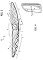
- the light cannot be positioned perpendicular to the longitudinal axis of the vehicle, but rather inclined with respect to two angles: the first is formed by rotating the light with respect to the axis Y (which exits from the plane of the figure); the second is formed by rotating it with respect to the axis X (see Figure 4).
- Figure 3 shows precisely a cell of the light according to the invention, designed for being installed so as to have the axis of the reflector oriented by the angle ⁇ with respect to the longitudinal axis of the motor vehicle.
- the primary reflector A is constituted by a surface of an elliptical, parabolic or hyperbolic type.
- Figure 3 represents the case of a parabolic type (similar to Figure 2), in which the axis of rotation of the parabola has an angle ⁇ with respect to the straight line perpendicular to the faces of the cell.
- the choice of the type of surface of the primary reflector A is dictated by the angle ⁇ , by the thickness of the device, and by considerations regarding the luminance of the cell.
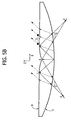
- Figure 5A illustrates a case where the surface of the primary is of a parabolic type, and the angle of collimation ⁇ is such that a part of the light reflected by the secondary reflector C arrives again on the primary reflector (in the portion designated by 4); this entails a loss of efficiency of the device or, in any case, a loss of control of part of the light. In order to prevent this effect, it is possible to resort, in the case of Figure 5A, to a different shape of the primary reflector.
- Figure 5B illustrates a type of primary reflector A of elliptical cross section with one focus in the source and the other focus determined with the following methodology: considering the left-hand side of the profile of the cell of Figure 5B, the focus 2 is determined as the intersection of the two extreme rays 1 and 4 reflected by the primary reflector A.
- the point 1 is the point of intersection between the primary reflector A and the transparent section B, the TIR angle determines the ray reflected by the point 1 of the primary reflector.
- the ray reflected by the point 4 is chosen so that the ray reflected by the secondary reflector C will exit from the cell with an angle ⁇ passing through the point 1, preventing it from arriving back, as occurred in the case of Figure 5A on the primary reflector A.
- the focus 2 of the primary reflector A determines an area 3 of the transparent section B from which rays do not exit. Said area 3 will present as an area of shadow, if the observer is positioned in the direction given by the angle ⁇ .
- the configuration of Figure B enables efficiency/control of the light emitted by the device not to be lost, but leads to an extension of the area of shadow represented by the primary reflector A.
- the primary reflector A can be built not having rotational symmetry as indicated in Figure 5C.
- the cross section of Figure 5C illustrates a surface having a cross section of an elliptical type in the left-hand area of the profile of the cell and of a parabolic type in the right-hand area.
- the secondary reflector in this example of light, is not a surface of rotation.
- the part of reflector C deflects the rays coming from the primary reflector A so that, after the interface B, they will exit with a preferential angle ⁇ to form the desired distribution of intensity.
- the part of reflector D receives the rays that impinge upon the interface B with an angle greater than the limit angle (TIR) and deflects them according to the same principle as that of the reflector C.
- TIR limit angle
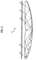
- the part of transparent surface B may be smooth, in which case the distribution of intensity is created by the reflecting surfaces C and D; there may be provided an additional transparent portion, on the internal surface of which there are present microlenses or prisms calculated so as to widen the distribution of light.
- Figure 6 is an example of configuration in which the array of microlenses is inserted in the internal part of a transparent portion set in front of the individual elementary cells. Said transparent portion bearing the microlenses may be colourless or else coloured.
- the dielectric plate which is designed for collimating the light emitted by the sources can be coloured; in both cases, the colour of the transparent portion must be such as to transmit all or almost all of the light of the wavelength emitted by the corresponding microsource or microsources.
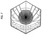
- Figure 7 is a front view of a hexagonal elementary cell.
- the chip-LED source is positioned in the centre and is visible in so far as the primary reflector A has been masked in order to highlight the absence of rotational symmetry of the secondary reflectors C and D.
- Figure 8 represents the distribution of intensity in which the excellent degree of control of the outgoing beam is highlighted.
- the value of efficiency of the device is equal to 70%, with a value of reflectance of the reflecting surfaces of 0.85.
- the number of sources for each individual cell that forms part of the light does not emerge as a constraint. It is in fact possible to set alongside one another a number of microsources about the axis of the individual elementary cell in order to increase the flow of light.
- Figure 9 illustrates, by way of example, a case in which a multitude of cells with a hexagonal shape have been set alongside one another.
Landscapes
- Engineering & Computer Science (AREA)
- General Engineering & Computer Science (AREA)
- Physics & Mathematics (AREA)
- Microelectronics & Electronic Packaging (AREA)
- Optics & Photonics (AREA)
- Mathematical Physics (AREA)
- Optical Elements Other Than Lenses (AREA)
- Non-Portable Lighting Devices Or Systems Thereof (AREA)
- Lighting Device Outwards From Vehicle And Optical Signal (AREA)
- Air-Conditioning For Vehicles (AREA)
Claims (25)
- Beleuchtungssystem, speziell ein Motorfahrzeuglicht, gebildet aus wenigstens einer elementaren Zelle, wobei jede Zelle enthält: ein transparentes dielektrisches Modul in der Form einer Platte (2), mit zwei gegenüberliegenden Hauptseiten (I, II); eine im Wesentlichen punktförmige Quelle (1) angelegt in der Nähe der ersten (I) der zwei Hauptseiten des Moduls; einen Primärreflektor (3) gebildet auf der zweiten (II) der Hauptseiten des Moduls zur erstmaligen Reflektion von Licht, das von der Lichtquelle (1) kommt, welches die Platte (2) durchquert hat; und einen sekundären Reflektor (4) gebildet auf der ersten Hauptseite (I) des Moduls zur Reflektion des Lichts zum zweiten Mal, welches bereits durch den primären Reflektor reflektiert wurde und zur Richtung desselben in Richtung der Außenseite des Moduls, auf der Seite der zweiten Hauptseite (II), damit es in einer vorbestimmten Richtung kollimiert wird, wobei:- der primäre Reflektor (3) aus zwei Teilen gebildet wird: einem im Wesentlichen gekrümmten zentralen Abschnitt (A), welcher mit einer reflektierenden Schicht (5) beschichtet ist, welche dazu bestimmt ist, einen Teil der Strahlen, die durch die Quelle (1) emittiert werden, zu reflektieren; und einen im Wesentlichen flachen und transparenten umfänglichen Abschnitt (B), welcher dazu bestimmt ist, in gesamter innerer Reflektion (TIR) einen weiteren Teil der Strahlen, welche von der Quelle (1) emittiert werden, zu reflektieren; und- der sekundäre Reflektor aus zwei Abschnitten gebildet wird: einem ersten Abschnitt (C), welcher mit einer reflektierenden Schicht beschichtet ist und dazu bestimmt ist das Licht, welches vom zentralen Abschnitt (A) des primären Reflektors reflektiert ist, aufzunehmen und dieses in Richtung des transparenten Abschnitts (B) des primären Reflektors zu reflektieren; und einen zweiten Abschnitt (D), welcher mit einer reflektierenden Schicht beschichtet ist und dazu bestimmt ist das Licht, welches in TIR durch den transparenten Abschnitt (B) reflektiert wurde, aufzunehmen und es wiederum nach außen durch den Abschnitt (B) zu reflektieren;gekennzeichnet dadurch, dass der sekundäre Reflektor (C) aus einer Vielzahl von Segmenten von quadratischen Oberflächen gebildet wird, z.B. Paraboloiden, Ellipsoiden oder Hyperboloiden, welche auf nicht-kontinuierliche Weise aneinander gerundet sind,
dadurch, dass der sekundäre Reflektor (D) aus einer Vielzahl von Segmenten von quadratischen Oberflächen gebildet wird, z.B. Paraboloiden, E1-lipsoiden oder Hyperboloiden, die auf nicht-kontinuierliche Weise aneinander gerundet sind, so dass das Licht in einer vorbestimmten Richtung, geneigt in Bezug auf die geometrische Achse (z) der Zelle kollimiert wird. - Vorrichtung gemäß Anspruch 1, dadurch gekennzeichnet, dass die reflektierenden Schichten auf den Oberflächen A, C und D Metallbeschichtungen sind.
- Vorrichtung gemäß Anspruch 1, dadurch gekennzeichnet, dass die reflektierenden Schichten auf den Oberflächen A, C und D mehrlagige dielektrische Beschichtungen sind.
- Vorrichtung gemäß Anspruch 1, dadurch gekennzeichnet, dass die reflektierenden Schicht auf der Oberfläche A teilweise transparent ist, so dass sie einen Teil des Lichts durchlässt, welches von der Quelle emittiert wird und auf den primären Reflektor auftrifft.
- Vorrichtung gemäß Anspruch 1, dadurch gekennzeichnet, dass der primäre Reflektor A durch eine Oberfläche gebildet wird, die durch Drehung von wenigstens einem Segment einer konischen Kurve erhalten wird (verstanden als Linie, die sich aus dem Schnitt des Konus mit einer Ebene ergibt) um eine Achse, die durch die Quelle senkrecht zu den Hauptoberflächen der Platte verläuft.
- Vorrichtung gemäß Anspruch 1, dadurch gekennzeichnet, dass die Quelle in der Nähe des Brennpunktes der konischen Kurve positioniert ist.
- Vorrichtung gemäß Anspruch 1, dadurch gekennzeichnet, dass das Segment der konischen Kurve ein Segment einer Parabel ist, die eine Achse hat, welche in Richtung der Außenseite um einen Winkel größer oder gleich dem TIR-Winkel geneigt ist.
- Vorrichtung gemäß Anspruch 1, dadurch gekennzeichnet, dass das Segment der konischen Kurve ein Segment einer Ellipse ist, welche den ersten Brennpunkt in der Nähe der Quelle hat.
- Vorrichtung gemäß Anspruch 1, dadurch gekennzeichnet, dass der primäre Reflektor A nicht durch eine Drehoberfläche gebildet wird.
- Vorrichtung gemäß Anspruch 1, dadurch gekennzeichnet, dass der Abschnitt A des primären Reflektors und der Abschnitt B des primären Reflektors so aneinander gerundet sind, dass sowohl das Profil als auch die Krümmung am Ort der Punkte der Rundung fortlaufend sind.
- Vorrichtung gemäß Anspruch 1, dadurch gekennzeichnet, dass der sekundäre Reflektor C durch eine Vielzahl von Segmenten von asymmetrischen Konen gebildet wird, welche entworfen sind, das Licht, das von einem ringförmigen Bild der Quelle kommt, wobei das Bild durch die Drehoberfläche des primären Reflektors A erzeugt wird, in eine vorbestimmte Richtung zu kollimieren.
- Vorrichtung gemäß Anspruch 11, dadurch gekennzeichnet, dass die quadratischen Oberflächen Rotationsparaboloide sind, deren Brennpunkt im virtuellen Bild der Quelle liegt, wobei das Bild durch den transparenten Abschnitt B des primären Reflektors erzeugt wird.
- Vorrichtung gemäß Anspruch 12, dadurch gekennzeichnet, dass die Rotationsparaboloide zueinander parallele Achsen haben, so dass sie das Licht in einer vorbestimmten Richtung kollimieren.
- Vorrichtung gemäß Anspruch 12, dadurch gekennzeichnet, dass die Rotationsparaboloide Achsen haben, die nicht zueinander parallel sind, und so orientiert sind, dass sie eine vorbestimmte Lichtstreuung erzeugen.
- Vorrichtung gemäß irgendeinem der vorhergehenden Ansprüche, dadurch gekennzeichnet, dass die transparente Platte farblos ist.
- Vorrichtung gemäß irgendeinem der vorhergehenden Ansprüche, dadurch gekennzeichnet, dass die transparente Platte gefärbt ist und dadurch, dass die Färbung jeder elementaren Zelle derartig ist, dass sie kein Licht absorbiert, das durch die Quelle dieser Zelle abgegeben wird.
- Vorrichtung gemäß irgendeinem der vorhergehenden Ansprüche, dadurch gekennzeichnet, dass in wenigstens einer der Zellen mehr als eine Quelle vorliegt, wobei die Quellen nahe zueinander positioniert sind.
- Vorrichtung gemäß irgendeinem der vorhergehenden Ansprüche, dadurch gekennzeichnet, dass die Quelle ein LED in der Form eines Chips ist, d.h. ohne Gehäuse.
- Vorrichtung gemäß Anspruch 18, dadurch gekennzeichnet, dass der Chip in die Platte eingelassen ist.
- Vorrichtung gemäß irgendeinem der vorhergehenden Ansprüche, dadurch gekennzeichnet, dass die Dicke der Platte geringer als 15 mm ist.
- Vorrichtung gemäß irgendeinem der vorhergehenden Ansprüche, dadurch gekennzeichnet, dass der zweite transparente Abschnitt in einer Position bereitgestellt ist, die dem Strahl entspricht, der aus der Platte herauskommt.
- Vorrichtung gemäß Anspruch 21, dadurch gekennzeichnet, dass der transparente Abschnitt gefärbt ist, während das Dielektrikum, das die Platte aufbaut, farblos ist.
- Vorrichtung gemäß Anspruch 21, dadurch gekennzeichnet, dass der transparente Abschnitt auf seiner inneren Oberfläche, die der Platte gegenüberliegt, eine Vielzahl von Mikrolinsen und/oder Prismen aufweist, welche dazu entworfen sind, den Lichtstrahl, der aus der Platte herauskommt, gleich zu richten/abzuleiten.
- Fahrzeuglicht, speziell ein Rücklicht, dadurch gekennzeichnet, dass es eine Vorrichtung gemäß irgendeinem der vorhergehenden Ansprüche enthält.
- Frontlicht für ein Fahrzeug dadurch gekennzeichnet, dass es eine Vorrichtung gemäß irgendeinem der vorhergehenden Ansprüche 1 bis 24 enthält.
Priority Applications (4)
| Application Number | Priority Date | Filing Date | Title |
|---|---|---|---|
| DE602004001128T DE602004001128T2 (de) | 2004-04-21 | 2004-04-21 | Dünne, plattenförmige Kraftfahrzeugleuchte |
| EP04425280A EP1589282B1 (de) | 2004-04-21 | 2004-04-21 | Dünne, plattenförmige Kraftfahrzeugleuchte |
| AT04425280T ATE329204T1 (de) | 2004-04-21 | 2004-04-21 | Dünne, plattenförmige kraftfahrzeugleuchte |
| ES04425280T ES2263128T3 (es) | 2004-04-21 | 2004-04-21 | Faro en forma de placa delgada para vehiculos automoviles. |
Applications Claiming Priority (1)
| Application Number | Priority Date | Filing Date | Title |
|---|---|---|---|
| EP04425280A EP1589282B1 (de) | 2004-04-21 | 2004-04-21 | Dünne, plattenförmige Kraftfahrzeugleuchte |
Publications (2)
| Publication Number | Publication Date |
|---|---|
| EP1589282A1 EP1589282A1 (de) | 2005-10-26 |
| EP1589282B1 true EP1589282B1 (de) | 2006-06-07 |
Family
ID=34932449
Family Applications (1)
| Application Number | Title | Priority Date | Filing Date |
|---|---|---|---|
| EP04425280A Expired - Lifetime EP1589282B1 (de) | 2004-04-21 | 2004-04-21 | Dünne, plattenförmige Kraftfahrzeugleuchte |
Country Status (4)
| Country | Link |
|---|---|
| EP (1) | EP1589282B1 (de) |
| AT (1) | ATE329204T1 (de) |
| DE (1) | DE602004001128T2 (de) |
| ES (1) | ES2263128T3 (de) |
Families Citing this family (12)
| Publication number | Priority date | Publication date | Assignee | Title |
|---|---|---|---|---|
| DE102006008199B4 (de) * | 2006-02-22 | 2016-02-04 | Hella Kgaa Hueck & Co. | Leuchteneinheit für Fahrzeuge |
| GB0712614D0 (en) | 2007-06-29 | 2007-08-08 | Dialight Lumidrives Ltd | Improved spatial luminance |
| JP5152572B2 (ja) * | 2008-03-24 | 2013-02-27 | スタンレー電気株式会社 | 車両前照灯 |
| NL1037239C2 (nl) * | 2009-08-31 | 2011-03-01 | Spanninga Metaal | Rijwiel en achterlicht voor een rijwiel. |
| JP5681513B2 (ja) * | 2011-02-08 | 2015-03-11 | 株式会社小糸製作所 | 車両用前照灯 |
| JP5944617B2 (ja) * | 2011-02-08 | 2016-07-05 | 株式会社小糸製作所 | 灯具ユニット |
| JP5707661B2 (ja) * | 2011-03-25 | 2015-04-30 | スタンレー電気株式会社 | 車両用灯具ユニット及び車両用灯具に用いられる導光体 |
| CN102506322A (zh) * | 2011-10-31 | 2012-06-20 | 中国科学院长春光学精密机械与物理研究所 | 一种用于光栅尺的平板型led高度准直照明系统 |
| CN102588787A (zh) * | 2012-02-14 | 2012-07-18 | 杭州光锥科技有限公司 | 基于反射透射型均匀大功率led光源 |
| US10295153B2 (en) * | 2013-08-22 | 2019-05-21 | Signify Holding B.V. | Optical system for producing uniform illumination |
| WO2023012651A1 (en) * | 2021-08-02 | 2023-02-09 | Varroc Engineering Limited | A vehicle tail-light assembly |
| DE102021129851A1 (de) * | 2021-11-16 | 2023-05-17 | HELLA GmbH & Co. KGaA | Lichtleiterelement für eine Beleuchtungsvorrichtung für ein Kraftfahrzeug |
Family Cites Families (7)
| Publication number | Priority date | Publication date | Assignee | Title |
|---|---|---|---|---|
| US5980054A (en) * | 1996-05-09 | 1999-11-09 | Matsushita Electric Industrial Co., Ltd. | Panel-form illuminating system |
| WO1999009349A1 (en) * | 1997-08-12 | 1999-02-25 | Decoma International Inc. | Bireflective lens element |
| DE20206829U1 (de) * | 2002-04-30 | 2002-09-05 | Automotive Lighting Reutlingen GmbH, 72762 Reutlingen | Leuchte, insbesondere Begrenzungsleuchte |
| FR2840388B1 (fr) * | 2002-05-31 | 2004-07-30 | Valeo Vision | Feu de signalisation comportant une piece optique realisant une fonction de signalisation de maniere autonome |
| JP4162935B2 (ja) * | 2002-07-04 | 2008-10-08 | 株式会社小糸製作所 | 車両用灯具 |
| JP2004103379A (ja) * | 2002-09-09 | 2004-04-02 | Koito Mfg Co Ltd | 車両用標識灯 |
| US6896381B2 (en) * | 2002-10-11 | 2005-05-24 | Light Prescriptions Innovators, Llc | Compact folded-optics illumination lens |
-
2004
- 2004-04-21 EP EP04425280A patent/EP1589282B1/de not_active Expired - Lifetime
- 2004-04-21 DE DE602004001128T patent/DE602004001128T2/de not_active Expired - Lifetime
- 2004-04-21 ES ES04425280T patent/ES2263128T3/es not_active Expired - Lifetime
- 2004-04-21 AT AT04425280T patent/ATE329204T1/de not_active IP Right Cessation
Also Published As
| Publication number | Publication date |
|---|---|
| DE602004001128D1 (de) | 2006-07-20 |
| ATE329204T1 (de) | 2006-06-15 |
| EP1589282A1 (de) | 2005-10-26 |
| ES2263128T3 (es) | 2006-12-01 |
| DE602004001128T2 (de) | 2006-12-14 |
Similar Documents
| Publication | Publication Date | Title |
|---|---|---|
| EP0890060B1 (de) | Beleuchtungssystem mit blenden aufweisenden mikroprismen | |
| US7874704B2 (en) | LED luminance-augmentation via specular retroreflection, including collimators that escape the étendue limit | |
| US8454205B2 (en) | LED devices for offset wide beam generation | |
| US8469567B2 (en) | Optical lens and vehicle lighting device using the same | |
| US8960980B2 (en) | Light source module having a curved optical unit | |
| US9260201B2 (en) | Light for an aircraft | |
| US12152744B2 (en) | Motor vehicle headlamp with multiple lighting modules on an inclined common plate | |
| EP1589282B1 (de) | Dünne, plattenförmige Kraftfahrzeugleuchte | |
| US4989125A (en) | Reflector using fresnel-type structures having a plurality of active faces | |
| US20090310379A1 (en) | Optical element and module for the projection of a light beam, and motor vehicle lamp including a plurality of such modules | |
| EP0798506B1 (de) | Kraftfahrzeug-Scheinwerfer | |
| EP2450725B1 (de) | Beleuchtungsvorrichtung | |
| US8562191B2 (en) | Vehicle light | |
| CN112524568A (zh) | 一种车灯透镜 | |
| CN217684748U (zh) | 车灯、投射组件和车辆 | |
| EP0371511B1 (de) | Scheinwerfer für Kraftfahrzeuge | |
| CN108826121A (zh) | 一种小体积星空投影灯 | |
| CN115016200A (zh) | 一种反射式补光器件和摄像机 | |
| US10907774B2 (en) | Light source unit | |
| US20250361997A1 (en) | Vehicle lamp | |
| JP4324133B2 (ja) | 導光板および平面照明装置 | |
| JP4422934B2 (ja) | 信号灯 | |
| US20260022813A1 (en) | Light-emitting module and vehicle lamp including the same | |
| JP2007257857A (ja) | 照明装置 | |
| US20230288039A1 (en) | Lens and lamp assembly |
Legal Events
| Date | Code | Title | Description |
|---|---|---|---|
| PUAI | Public reference made under article 153(3) epc to a published international application that has entered the european phase |
Free format text: ORIGINAL CODE: 0009012 |
|
| 17P | Request for examination filed |
Effective date: 20050404 |
|
| AK | Designated contracting states |
Kind code of ref document: A1 Designated state(s): AT BE BG CH CY CZ DE DK EE ES FI FR GB GR HU IE IT LI LU MC NL PL PT RO SE SI SK TR |
|
| AX | Request for extension of the european patent |
Extension state: AL HR LT LV MK |
|
| GRAP | Despatch of communication of intention to grant a patent |
Free format text: ORIGINAL CODE: EPIDOSNIGR1 |
|
| RIN1 | Information on inventor provided before grant (corrected) |
Inventor name: BERNARD, STEFANO, C/O C.R.F. SOCIETAE CONSORTILE Inventor name: REPETTO, PIERMARIO Inventor name: PERLO, PIERO Inventor name: CAPELLO, DAVIDE Inventor name: BOLLEA, DENIS |
|
| GRAS | Grant fee paid |
Free format text: ORIGINAL CODE: EPIDOSNIGR3 |
|
| GRAA | (expected) grant |
Free format text: ORIGINAL CODE: 0009210 |
|
| AK | Designated contracting states |
Kind code of ref document: B1 Designated state(s): AT BE BG CH CY CZ DE DK EE ES FI FR GB GR HU IE IT LI LU MC NL PL PT RO SE SI SK TR |
|
| PG25 | Lapsed in a contracting state [announced via postgrant information from national office to epo] |
Ref country code: IT Free format text: LAPSE BECAUSE OF FAILURE TO SUBMIT A TRANSLATION OF THE DESCRIPTION OR TO PAY THE FEE WITHIN THE PRESCRIBED TIME-LIMIT;WARNING: LAPSES OF ITALIAN PATENTS WITH EFFECTIVE DATE BEFORE 2007 MAY HAVE OCCURRED AT ANY TIME BEFORE 2007. THE CORRECT EFFECTIVE DATE MAY BE DIFFERENT FROM THE ONE RECORDED. Effective date: 20060607 Ref country code: BE Free format text: LAPSE BECAUSE OF FAILURE TO SUBMIT A TRANSLATION OF THE DESCRIPTION OR TO PAY THE FEE WITHIN THE PRESCRIBED TIME-LIMIT Effective date: 20060607 Ref country code: AT Free format text: LAPSE BECAUSE OF FAILURE TO SUBMIT A TRANSLATION OF THE DESCRIPTION OR TO PAY THE FEE WITHIN THE PRESCRIBED TIME-LIMIT Effective date: 20060607 Ref country code: RO Free format text: LAPSE BECAUSE OF FAILURE TO SUBMIT A TRANSLATION OF THE DESCRIPTION OR TO PAY THE FEE WITHIN THE PRESCRIBED TIME-LIMIT Effective date: 20060607 Ref country code: SK Free format text: LAPSE BECAUSE OF FAILURE TO SUBMIT A TRANSLATION OF THE DESCRIPTION OR TO PAY THE FEE WITHIN THE PRESCRIBED TIME-LIMIT Effective date: 20060607 Ref country code: SI Free format text: LAPSE BECAUSE OF FAILURE TO SUBMIT A TRANSLATION OF THE DESCRIPTION OR TO PAY THE FEE WITHIN THE PRESCRIBED TIME-LIMIT Effective date: 20060607 Ref country code: CH Free format text: LAPSE BECAUSE OF FAILURE TO SUBMIT A TRANSLATION OF THE DESCRIPTION OR TO PAY THE FEE WITHIN THE PRESCRIBED TIME-LIMIT Effective date: 20060607 Ref country code: FI Free format text: LAPSE BECAUSE OF FAILURE TO SUBMIT A TRANSLATION OF THE DESCRIPTION OR TO PAY THE FEE WITHIN THE PRESCRIBED TIME-LIMIT Effective date: 20060607 Ref country code: CZ Free format text: LAPSE BECAUSE OF FAILURE TO SUBMIT A TRANSLATION OF THE DESCRIPTION OR TO PAY THE FEE WITHIN THE PRESCRIBED TIME-LIMIT Effective date: 20060607 Ref country code: LI Free format text: LAPSE BECAUSE OF FAILURE TO SUBMIT A TRANSLATION OF THE DESCRIPTION OR TO PAY THE FEE WITHIN THE PRESCRIBED TIME-LIMIT Effective date: 20060607 Ref country code: NL Free format text: LAPSE BECAUSE OF FAILURE TO SUBMIT A TRANSLATION OF THE DESCRIPTION OR TO PAY THE FEE WITHIN THE PRESCRIBED TIME-LIMIT Effective date: 20060607 Ref country code: PL Free format text: LAPSE BECAUSE OF FAILURE TO SUBMIT A TRANSLATION OF THE DESCRIPTION OR TO PAY THE FEE WITHIN THE PRESCRIBED TIME-LIMIT Effective date: 20060607 |
|
| REG | Reference to a national code |
Ref country code: GB Ref legal event code: FG4D |
|
| REG | Reference to a national code |
Ref country code: CH Ref legal event code: EP |
|
| AKX | Designation fees paid |
Designated state(s): AT BE BG CH CY CZ DE DK EE ES FI FR GB GR HU IE IT LI LU MC NL PL PT RO SE SI SK TR |
|
| REG | Reference to a national code |
Ref country code: IE Ref legal event code: FG4D |
|
| REF | Corresponds to: |
Ref document number: 602004001128 Country of ref document: DE Date of ref document: 20060720 Kind code of ref document: P |
|
| PG25 | Lapsed in a contracting state [announced via postgrant information from national office to epo] |
Ref country code: DK Free format text: LAPSE BECAUSE OF FAILURE TO SUBMIT A TRANSLATION OF THE DESCRIPTION OR TO PAY THE FEE WITHIN THE PRESCRIBED TIME-LIMIT Effective date: 20060907 |
|
| REG | Reference to a national code |
Ref country code: SE Ref legal event code: TRGR |
|
| PG25 | Lapsed in a contracting state [announced via postgrant information from national office to epo] |
Ref country code: PT Free format text: LAPSE BECAUSE OF FAILURE TO SUBMIT A TRANSLATION OF THE DESCRIPTION OR TO PAY THE FEE WITHIN THE PRESCRIBED TIME-LIMIT Effective date: 20061107 |
|
| NLV1 | Nl: lapsed or annulled due to failure to fulfill the requirements of art. 29p and 29m of the patents act | ||
| REG | Reference to a national code |
Ref country code: ES Ref legal event code: FG2A Ref document number: 2263128 Country of ref document: ES Kind code of ref document: T3 |
|
| REG | Reference to a national code |
Ref country code: CH Ref legal event code: PL |
|
| ET | Fr: translation filed | ||
| PLBE | No opposition filed within time limit |
Free format text: ORIGINAL CODE: 0009261 |
|
| STAA | Information on the status of an ep patent application or granted ep patent |
Free format text: STATUS: NO OPPOSITION FILED WITHIN TIME LIMIT |
|
| 26N | No opposition filed |
Effective date: 20070308 |
|
| PG25 | Lapsed in a contracting state [announced via postgrant information from national office to epo] |
Ref country code: GR Free format text: LAPSE BECAUSE OF FAILURE TO SUBMIT A TRANSLATION OF THE DESCRIPTION OR TO PAY THE FEE WITHIN THE PRESCRIBED TIME-LIMIT Effective date: 20060908 |
|
| PG25 | Lapsed in a contracting state [announced via postgrant information from national office to epo] |
Ref country code: IE Free format text: LAPSE BECAUSE OF NON-PAYMENT OF DUE FEES Effective date: 20070423 |
|
| PG25 | Lapsed in a contracting state [announced via postgrant information from national office to epo] |
Ref country code: BG Free format text: LAPSE BECAUSE OF FAILURE TO SUBMIT A TRANSLATION OF THE DESCRIPTION OR TO PAY THE FEE WITHIN THE PRESCRIBED TIME-LIMIT Effective date: 20060907 |
|
| PG25 | Lapsed in a contracting state [announced via postgrant information from national office to epo] |
Ref country code: EE Free format text: LAPSE BECAUSE OF FAILURE TO SUBMIT A TRANSLATION OF THE DESCRIPTION OR TO PAY THE FEE WITHIN THE PRESCRIBED TIME-LIMIT Effective date: 20060607 |
|
| PGFP | Annual fee paid to national office [announced via postgrant information from national office to epo] |
Ref country code: ES Payment date: 20080520 Year of fee payment: 5 |
|
| PGRI | Patent reinstated in contracting state [announced from national office to epo] |
Ref country code: IT Effective date: 20080601 |
|
| PGFP | Annual fee paid to national office [announced via postgrant information from national office to epo] |
Ref country code: SE Payment date: 20080408 Year of fee payment: 5 |
|
| PGFP | Annual fee paid to national office [announced via postgrant information from national office to epo] |
Ref country code: GB Payment date: 20080423 Year of fee payment: 5 |
|
| PG25 | Lapsed in a contracting state [announced via postgrant information from national office to epo] |
Ref country code: MC Free format text: LAPSE BECAUSE OF NON-PAYMENT OF DUE FEES Effective date: 20070430 |
|
| PG25 | Lapsed in a contracting state [announced via postgrant information from national office to epo] |
Ref country code: LU Free format text: LAPSE BECAUSE OF NON-PAYMENT OF DUE FEES Effective date: 20070421 Ref country code: CY Free format text: LAPSE BECAUSE OF FAILURE TO SUBMIT A TRANSLATION OF THE DESCRIPTION OR TO PAY THE FEE WITHIN THE PRESCRIBED TIME-LIMIT Effective date: 20060607 |
|
| PG25 | Lapsed in a contracting state [announced via postgrant information from national office to epo] |
Ref country code: HU Free format text: LAPSE BECAUSE OF FAILURE TO SUBMIT A TRANSLATION OF THE DESCRIPTION OR TO PAY THE FEE WITHIN THE PRESCRIBED TIME-LIMIT Effective date: 20061208 Ref country code: TR Free format text: LAPSE BECAUSE OF FAILURE TO SUBMIT A TRANSLATION OF THE DESCRIPTION OR TO PAY THE FEE WITHIN THE PRESCRIBED TIME-LIMIT Effective date: 20060607 |
|
| EUG | Se: european patent has lapsed | ||
| GBPC | Gb: european patent ceased through non-payment of renewal fee |
Effective date: 20090421 |
|
| PG25 | Lapsed in a contracting state [announced via postgrant information from national office to epo] |
Ref country code: GB Free format text: LAPSE BECAUSE OF NON-PAYMENT OF DUE FEES Effective date: 20090421 |
|
| REG | Reference to a national code |
Ref country code: ES Ref legal event code: FD2A Effective date: 20090422 |
|
| PG25 | Lapsed in a contracting state [announced via postgrant information from national office to epo] |
Ref country code: ES Free format text: LAPSE BECAUSE OF NON-PAYMENT OF DUE FEES Effective date: 20090422 |
|
| PG25 | Lapsed in a contracting state [announced via postgrant information from national office to epo] |
Ref country code: IT Free format text: LAPSE BECAUSE OF NON-PAYMENT OF DUE FEES Effective date: 20090421 |
|
| PG25 | Lapsed in a contracting state [announced via postgrant information from national office to epo] |
Ref country code: SE Free format text: LAPSE BECAUSE OF NON-PAYMENT OF DUE FEES Effective date: 20090422 |
|
| PGRI | Patent reinstated in contracting state [announced from national office to epo] |
Ref country code: IT Effective date: 20110616 |
|
| REG | Reference to a national code |
Ref country code: FR Ref legal event code: PLFP Year of fee payment: 13 |
|
| REG | Reference to a national code |
Ref country code: FR Ref legal event code: PLFP Year of fee payment: 14 |
|
| PGFP | Annual fee paid to national office [announced via postgrant information from national office to epo] |
Ref country code: FR Payment date: 20170428 Year of fee payment: 14 |
|
| PGFP | Annual fee paid to national office [announced via postgrant information from national office to epo] |
Ref country code: IT Payment date: 20170419 Year of fee payment: 14 |
|
| PGFP | Annual fee paid to national office [announced via postgrant information from national office to epo] |
Ref country code: DE Payment date: 20170630 Year of fee payment: 14 |
|
| REG | Reference to a national code |
Ref country code: DE Ref legal event code: R079 Ref document number: 602004001128 Country of ref document: DE Free format text: PREVIOUS MAIN CLASS: F21S0008100000 Ipc: F21S0043000000 |
|
| REG | Reference to a national code |
Ref country code: DE Ref legal event code: R119 Ref document number: 602004001128 Country of ref document: DE |
|
| PG25 | Lapsed in a contracting state [announced via postgrant information from national office to epo] |
Ref country code: DE Free format text: LAPSE BECAUSE OF NON-PAYMENT OF DUE FEES Effective date: 20181101 |
|
| PG25 | Lapsed in a contracting state [announced via postgrant information from national office to epo] |
Ref country code: IT Free format text: LAPSE BECAUSE OF NON-PAYMENT OF DUE FEES Effective date: 20180421 Ref country code: FR Free format text: LAPSE BECAUSE OF NON-PAYMENT OF DUE FEES Effective date: 20180430 |