EP1589282B1 - Thin-plate light for motor vehicles - Google Patents
Thin-plate light for motor vehicles Download PDFInfo
- Publication number
- EP1589282B1 EP1589282B1 EP04425280A EP04425280A EP1589282B1 EP 1589282 B1 EP1589282 B1 EP 1589282B1 EP 04425280 A EP04425280 A EP 04425280A EP 04425280 A EP04425280 A EP 04425280A EP 1589282 B1 EP1589282 B1 EP 1589282B1
- Authority
- EP
- European Patent Office
- Prior art keywords
- source
- light
- section
- primary reflector
- reflecting
- Prior art date
- Legal status (The legal status is an assumption and is not a legal conclusion. Google has not performed a legal analysis and makes no representation as to the accuracy of the status listed.)
- Expired - Lifetime
Links
- 230000002093 peripheral effect Effects 0.000 claims abstract description 5
- 238000000576 coating method Methods 0.000 claims description 6
- 238000004040 coloring Methods 0.000 claims 1
- 239000002184 metal Substances 0.000 claims 1
- 239000011248 coating agent Substances 0.000 description 4
- 230000003287 optical effect Effects 0.000 description 2
- 238000004088 simulation Methods 0.000 description 2
- 238000010276 construction Methods 0.000 description 1
- 230000000694 effects Effects 0.000 description 1
- 239000000463 material Substances 0.000 description 1
- 238000000034 method Methods 0.000 description 1
- 238000005457 optimization Methods 0.000 description 1
- 229920002994 synthetic fiber Polymers 0.000 description 1
Images


Classifications
-
- F—MECHANICAL ENGINEERING; LIGHTING; HEATING; WEAPONS; BLASTING
- F21—LIGHTING
- F21V—FUNCTIONAL FEATURES OR DETAILS OF LIGHTING DEVICES OR SYSTEMS THEREOF; STRUCTURAL COMBINATIONS OF LIGHTING DEVICES WITH OTHER ARTICLES, NOT OTHERWISE PROVIDED FOR
- F21V7/00—Reflectors for light sources
- F21V7/0091—Reflectors for light sources using total internal reflection
-
- F—MECHANICAL ENGINEERING; LIGHTING; HEATING; WEAPONS; BLASTING
- F21—LIGHTING
- F21S—NON-PORTABLE LIGHTING DEVICES; SYSTEMS THEREOF; VEHICLE LIGHTING DEVICES SPECIALLY ADAPTED FOR VEHICLE EXTERIORS
- F21S41/00—Illuminating devices specially adapted for vehicle exteriors, e.g. headlamps
- F21S41/10—Illuminating devices specially adapted for vehicle exteriors, e.g. headlamps characterised by the light source
- F21S41/14—Illuminating devices specially adapted for vehicle exteriors, e.g. headlamps characterised by the light source characterised by the type of light source
- F21S41/141—Light emitting diodes [LED]
- F21S41/143—Light emitting diodes [LED] the main emission direction of the LED being parallel to the optical axis of the illuminating device
-
- F—MECHANICAL ENGINEERING; LIGHTING; HEATING; WEAPONS; BLASTING
- F21—LIGHTING
- F21S—NON-PORTABLE LIGHTING DEVICES; SYSTEMS THEREOF; VEHICLE LIGHTING DEVICES SPECIALLY ADAPTED FOR VEHICLE EXTERIORS
- F21S41/00—Illuminating devices specially adapted for vehicle exteriors, e.g. headlamps
- F21S41/10—Illuminating devices specially adapted for vehicle exteriors, e.g. headlamps characterised by the light source
- F21S41/14—Illuminating devices specially adapted for vehicle exteriors, e.g. headlamps characterised by the light source characterised by the type of light source
- F21S41/141—Light emitting diodes [LED]
- F21S41/151—Light emitting diodes [LED] arranged in one or more lines
- F21S41/153—Light emitting diodes [LED] arranged in one or more lines arranged in a matrix
-
- F—MECHANICAL ENGINEERING; LIGHTING; HEATING; WEAPONS; BLASTING
- F21—LIGHTING
- F21S—NON-PORTABLE LIGHTING DEVICES; SYSTEMS THEREOF; VEHICLE LIGHTING DEVICES SPECIALLY ADAPTED FOR VEHICLE EXTERIORS
- F21S41/00—Illuminating devices specially adapted for vehicle exteriors, e.g. headlamps
- F21S41/20—Illuminating devices specially adapted for vehicle exteriors, e.g. headlamps characterised by refractors, transparent cover plates, light guides or filters
- F21S41/24—Light guides
-
- F—MECHANICAL ENGINEERING; LIGHTING; HEATING; WEAPONS; BLASTING
- F21—LIGHTING
- F21S—NON-PORTABLE LIGHTING DEVICES; SYSTEMS THEREOF; VEHICLE LIGHTING DEVICES SPECIALLY ADAPTED FOR VEHICLE EXTERIORS
- F21S43/00—Signalling devices specially adapted for vehicle exteriors, e.g. brake lamps, direction indicator lights or reversing lights
- F21S43/20—Signalling devices specially adapted for vehicle exteriors, e.g. brake lamps, direction indicator lights or reversing lights characterised by refractors, transparent cover plates, light guides or filters
- F21S43/235—Light guides
- F21S43/236—Light guides characterised by the shape of the light guide
- F21S43/241—Light guides characterised by the shape of the light guide of complex shape
-
- F—MECHANICAL ENGINEERING; LIGHTING; HEATING; WEAPONS; BLASTING
- F21—LIGHTING
- F21S—NON-PORTABLE LIGHTING DEVICES; SYSTEMS THEREOF; VEHICLE LIGHTING DEVICES SPECIALLY ADAPTED FOR VEHICLE EXTERIORS
- F21S43/00—Signalling devices specially adapted for vehicle exteriors, e.g. brake lamps, direction indicator lights or reversing lights
- F21S43/20—Signalling devices specially adapted for vehicle exteriors, e.g. brake lamps, direction indicator lights or reversing lights characterised by refractors, transparent cover plates, light guides or filters
- F21S43/235—Light guides
- F21S43/242—Light guides characterised by the emission area
- F21S43/243—Light guides characterised by the emission area emitting light from one or more of its extremities
-
- F—MECHANICAL ENGINEERING; LIGHTING; HEATING; WEAPONS; BLASTING
- F21—LIGHTING
- F21S—NON-PORTABLE LIGHTING DEVICES; SYSTEMS THEREOF; VEHICLE LIGHTING DEVICES SPECIALLY ADAPTED FOR VEHICLE EXTERIORS
- F21S43/00—Signalling devices specially adapted for vehicle exteriors, e.g. brake lamps, direction indicator lights or reversing lights
- F21S43/20—Signalling devices specially adapted for vehicle exteriors, e.g. brake lamps, direction indicator lights or reversing lights characterised by refractors, transparent cover plates, light guides or filters
- F21S43/235—Light guides
- F21S43/249—Light guides with two or more light sources being coupled into the light guide
-
- F—MECHANICAL ENGINEERING; LIGHTING; HEATING; WEAPONS; BLASTING
- F21—LIGHTING
- F21S—NON-PORTABLE LIGHTING DEVICES; SYSTEMS THEREOF; VEHICLE LIGHTING DEVICES SPECIALLY ADAPTED FOR VEHICLE EXTERIORS
- F21S43/00—Signalling devices specially adapted for vehicle exteriors, e.g. brake lamps, direction indicator lights or reversing lights
- F21S43/30—Signalling devices specially adapted for vehicle exteriors, e.g. brake lamps, direction indicator lights or reversing lights characterised by reflectors
- F21S43/31—Optical layout thereof
- F21S43/315—Optical layout thereof using total internal reflection
-
- F—MECHANICAL ENGINEERING; LIGHTING; HEATING; WEAPONS; BLASTING
- F21—LIGHTING
- F21V—FUNCTIONAL FEATURES OR DETAILS OF LIGHTING DEVICES OR SYSTEMS THEREOF; STRUCTURAL COMBINATIONS OF LIGHTING DEVICES WITH OTHER ARTICLES, NOT OTHERWISE PROVIDED FOR
- F21V7/00—Reflectors for light sources
- F21V7/0008—Reflectors for light sources providing for indirect lighting
-
- F—MECHANICAL ENGINEERING; LIGHTING; HEATING; WEAPONS; BLASTING
- F21—LIGHTING
- F21Y—INDEXING SCHEME ASSOCIATED WITH SUBCLASSES F21K, F21L, F21S and F21V, RELATING TO THE FORM OR THE KIND OF THE LIGHT SOURCES OR OF THE COLOUR OF THE LIGHT EMITTED
- F21Y2115/00—Light-generating elements of semiconductor light sources
- F21Y2115/10—Light-emitting diodes [LED]
Landscapes
- Engineering & Computer Science (AREA)
- General Engineering & Computer Science (AREA)
- Physics & Mathematics (AREA)
- Microelectronics & Electronic Packaging (AREA)
- Optics & Photonics (AREA)
- Mathematical Physics (AREA)
- Optical Elements Other Than Lenses (AREA)
- Non-Portable Lighting Devices Or Systems Thereof (AREA)
- Air-Conditioning For Vehicles (AREA)
- Lighting Device Outwards From Vehicle And Optical Signal (AREA)
Abstract
Description
- The present invention relates to the field of lighting systems, and in particular lights for motor vehicles, of the type comprising one or more elementary cells, each including: a transparent dielectric module in the form of a plate, with two opposite main faces; a substantially point-like source set in the proximity of a first one of the two main faces of said module; a primary reflector formed on the second of the main faces of the module for reflecting a first time the light coming from the source that has traversed the plate; and a secondary reflector formed on the first main face of said module, for reflecting a second time the light already reflected by the primary reflector and directing it towards the outside of the module, on the side of said second main face, so as to collimate it in a pre-determined direction.
- A lighting system of the type specified above has already been proposed by the present applicant in the European patent No. EP 0 766 115 B1 and in the corresponding U.S. patent No. US 5 841 596, as likewise in the European patent No. EP 0 767 393 B1 and in the corresponding U.S. patent No. US 5 884 995. In said system, illustrated in Figure 1 of the annexed plate of drawings, the individual collimation cell operates in a mode similar to a telescope of the Cassegrain type. With reference to Figure 1, a point-
like light source 1 is located in the proximity of a first face I of atransparent plate 2 made of plastic material. The light emitted by thesource 1 is coupled within theplate 2 through a transparent portion of said face I, impinges upon aprimary reflector 3 set on the second face II of the transparent portion and generally obtained by coating a portion of said face II with a reflecting layer, and is reflected by saidprimary reflector 3 towards asecondary reflector 4 set on the face I about said transparent portion and generally obtained by coating a portion of said face I with a reflecting layer. The light is again reflected by thesecondary reflector 4 towards the face II and exits from the plate through a transparent portion of said face II, undergoing a refraction. Theprimary reflector 3 andsecondary reflector 4 have shapes which are designed for producing in combination a collimation of the beam emitted by the point-like source 1. The point-like source 1 can be located in a position corresponding to the transparent portion of theface 1 and possibly englobed in the plate in a position corresponding to said transparent portion. - In the above known solution, only one portion of the rays emitted by the source (which typically has a lambertian emission lobe) is collected by the primary reflector, where a significant portion of said rays is collected by the transparent portion of the face II, through which the rays exit from the plate. A lighting system according to the preamble of
claim 1 is known from US 2004/070855. - The purpose of the present invention is to improve the performance of the optical system proposed previously by increasing control of the light distribution and hence the value of intensity in a pre-determined direction.
- According to the present invention, the aforesaid purpose is achieved by a lighting system according to
claim 1. - In the system according to the invention, the following two solutions are consequently combined together:
- 1) the primary reflector A subtends an angle, with respect to the source, so that the rays emitted by the source at larger angles are reflected by the transparent portion B of the face II as a result of TIR; and
- 2) the secondary reflector consists of two portions: a portion C, which operates prevalently on the rays reflected by the primary reflector A; and a portion D, which operates prevalently on the rays reflected by TIR by the transparent portion B of the face II.
- The primary reflector A is radiused to the transparent portion B with a continuous profile and with a continuous curvature, so that the portions C and D of the secondary reflector operate in a substantially exclusive way on the rays reflected by the primary reflector A and by the transparent portion B of the face II, respectively.
- Thanks to said solution, it is possible to design the reflector C so as to collimate the rays coming from the reflector A, and the reflector D so as to collimate the rays coming from the transparent portion B, thus maximizing control of the distribution. A superimposition, even a partial one, of the rays (reflected by the primary reflector) on the secondary reflector would not enable optimization of the secondary reflector in said region of superimposition.
- Further advantageous characteristics of the invention are specified in the annexed claims.
- The characteristics and advantages of the present invention will emerge clearly evident in the course of the ensuing detailed description, which is provided purely by way of non-limiting example, with reference to the attached plate of drawings, in which:
- Figure 1 is a cross-sectional view of a cell of the light according to the known art;
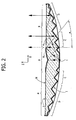
- Figure 2 is a cross-sectional view of a cell of the light according to a first embodiment which does not form part of the invention, with rotational symmetry, which is designed to be installed on a motor vehicle so as to have the axis of revolution of the reflector parallel to the longitudinal axis of the vehicle;
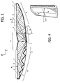
- Figure 3 is a cross-sectional view of a cell of the light according to a second embodiment of the invention, which does not present rotational symmetry, and which is designed to be installed on a motor vehicle so as to have the axis of revolution of the reflector inclined by an angle β with respect to the longitudinal axis of the vehicle;
- Figure 4 is a perspective view of a light according to the invention, designed to be installed on a motor vehicle with the axis of the reflector not coinciding with the longitudinal axis of the vehicle;
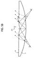
- Figures 5A, 5B, and 5C illustrate a cell of the light according to three variants of the invention in the case where the primary reflector is of a parabolic type (Figure 5A), of an elliptical type (Figure 5B), and not with rotational symmetry (Figure 5C);
- Figure 6 illustrates a cell of the light according to a further variant of the invention, in which the secondary reflector deviates the rays by a pre-determined angle, and a transparent portion is provided that is equipped with micro-optical systems for creating the required photometric pattern;
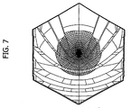
- Figure 7 illustrates a cell of the light according to a further embodiment, with a hexagonal shape, in which the primary reflector A has not been illustrated in order to highlight the secondary reflector made up of the parts C and D, the chip-LED source being set at the centre of the cell;
- Figure 8 illustrates a simulation of the distribution of the light intensity obtained with a non-sequential ray-tracing software, which shows control of the light distribution achieved for an angle β of 45°; and
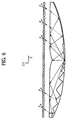
- Figure 9 is a perspective view of a light according to the invention made up of a plurality of hexagonal cells.
- Figure 2 is a cross-sectional view of a first embodiment of the collimator which does not form part of the present invention, in a plane of cross section perpendicular to the plate. The parts corresponding to those of Figure 1 are designated by the same reference numbers. Thus, the point-like light source (typically a chip-LED) is designated by 1. The plate, made of synthetic material, is designated by 2, and I and II designate the two main faces of the
plate 2 on which theprimary reflector 3 and thesecondary reflector 4 are formed. As illustrated above, theprimary reflector 3 has a central section A, which is reflecting in so far as it is equipped with a reflecting coating 5, and a peripheral section B, which does not have a reflecting coating, but gives rise to a total internal reflection (TIR) of the rays of light coming from inside the plate with an angle of inclination with respect to the vertical direction of the figure greater than a given value. - Consequently, all the rays R1 coming from the
source 1 that impinge upon the central section A of the primary reflector are reflected by the latter on the section C (which is a central annular area of the face I) of the secondary reflector, which in turn reflects them outwards in a direction substantially perpendicular to the section B, so that the latter allows them to pass outwards. All of the rays R2 coming from thesource 1 that impinge directly upon the peripheral section B of the primary reflector are reflected by this by TIR on the peripheral section D of the secondary reflector, which then reflects them outwards, again in a direction substantially perpendicular to the section B, so that the latter allows them to pass outwards. - In the example illustrated in Figure 2, the profile of the right-hand part (with reference to the figure) of the section A of the primary reflector is a profile of parabola with focus in a point corresponding to the source and axis AX inclined by an angle α with respect to the vertical. The left-hand part of the section A has likewise an axis passing through the source and set in a way specularly symmetrical with respect to the axis AX. Consequently, said section A collimates the rays emitted by the source with an angle α on the secondary reflector C.
- The size of the primary reflector A is such as to subtend an angle with respect to the source again equal to α, so that the point of radiusing between the sections A and B is continuous both in profile and in curvature. The angle α is chosen so as to be greater than the TIR angle so as to guarantee conditions of TIR on the entire section B of the face II. The choice of an angle slightly greater than the TIR angle enables minimization of the size of the primary reflector A.
- As already mentioned, the rays reflected by the primary reflector A are subsequently reflected by the secondary reflector C. The rays reflected by the transparent portion B are instead reflected by the secondary reflector D. In the configuration of Figure 2, the light is installed on a motor vehicle so that the axis z perpendicular to the surface of the cell is substantially parallel to the longitudinal axis of the vehicle.
- The primary reflector A generates an annular image of the point-like source. Said image can be: at infinity, in the case of section A being parabolic; virtual, in the case of section A being hyperbolic; or real, in the case of section A being elliptical. The transparent reflecting portion B generates, instead, a virtual point-like image of the chip-LED.
- The secondary reflector C is a complex surface that operates on the rays reflected by the primary reflector A in order to generate a desired distribution of light. The secondary reflector D operates, instead, on the rays reflected by the transparent reflector B to generate a desired distribution of light. Each of the two surfaces C and D can be segmented into a number of sectors so as to have an envelope in common (and continuous in the point of radiusing).
- As very frequently occurs, the light cannot be positioned perpendicular to the longitudinal axis of the vehicle, but rather inclined with respect to two angles: the first is formed by rotating the light with respect to the axis Y (which exits from the plane of the figure); the second is formed by rotating it with respect to the axis X (see Figure 4).
- These two rotations are equivalent, on account of the design of the optical surfaces, to just one rotation. In fact, we shall introduce a unit vector p that defines the direction of the longitudinal axis of the vehicle. We shall define, then, a new system of cartesian co-ordinates X', Y', Z', in which Z' = Z and the axis X' coincides with the projection of the unit vector p on the external surface of the light. In the system X', Y', Z', the two rotations defined above are equivalent to just one rotation with respect to the axis Y', with an angle comprised between the unit vector p and the plane X',Y'.
- For this reason, on account of the design of the reflecting surfaces, it is sufficient to consider just one angle of rotation with respect to the axis Y designated, in Figure 3, by β. Figure 3 shows precisely a cell of the light according to the invention, designed for being installed so as to have the axis of the reflector oriented by the angle β with respect to the longitudinal axis of the motor vehicle.
- The primary reflector A is constituted by a surface of an elliptical, parabolic or hyperbolic type. Figure 3 represents the case of a parabolic type (similar to Figure 2), in which the axis of rotation of the parabola has an angle α with respect to the straight line perpendicular to the faces of the cell.
- The choice of the type of surface of the primary reflector A is dictated by the angle β, by the thickness of the device, and by considerations regarding the luminance of the cell.
- Figure 5A illustrates a case where the surface of the primary is of a parabolic type, and the angle of collimation β is such that a part of the light reflected by the secondary reflector C arrives again on the primary reflector (in the portion designated by 4); this entails a loss of efficiency of the device or, in any case, a loss of control of part of the light. In order to prevent this effect, it is possible to resort, in the case of Figure 5A, to a different shape of the primary reflector. Figure 5B illustrates a type of primary reflector A of elliptical cross section with one focus in the source and the other focus determined with the following methodology: considering the left-hand side of the profile of the cell of Figure 5B, the
focus 2 is determined as the intersection of the twoextreme rays point 1 is the point of intersection between the primary reflector A and the transparent section B, the TIR angle determines the ray reflected by thepoint 1 of the primary reflector. The ray reflected by thepoint 4 is chosen so that the ray reflected by the secondary reflector C will exit from the cell with an angle β passing through thepoint 1, preventing it from arriving back, as occurred in the case of Figure 5A on the primary reflector A. Considering the right-hand side of the profile of the cell of Figure 5B, it is noted that thefocus 2 of the primary reflector A determines anarea 3 of the transparent section B from which rays do not exit. Saidarea 3 will present as an area of shadow, if the observer is positioned in the direction given by the angle β. The configuration of Figure B enables efficiency/control of the light emitted by the device not to be lost, but leads to an extension of the area of shadow represented by the primary reflector A. - In order to overcome both of the drawbacks, loss of efficiency/control and lack of uniformity of luminance, the primary reflector A can be built not having rotational symmetry as indicated in Figure 5C. The cross section of Figure 5C illustrates a surface having a cross section of an elliptical type in the left-hand area of the profile of the cell and of a parabolic type in the right-hand area.
- The secondary reflector, in this example of light, is not a surface of rotation. The part of reflector C deflects the rays coming from the primary reflector A so that, after the interface B, they will exit with a preferential angle β to form the desired distribution of intensity. The part of reflector D receives the rays that impinge upon the interface B with an angle greater than the limit angle (TIR) and deflects them according to the same principle as that of the reflector C.
- The part of transparent surface B may be smooth, in which case the distribution of intensity is created by the reflecting surfaces C and D; there may be provided an additional transparent portion, on the internal surface of which there are present microlenses or prisms calculated so as to widen the distribution of light. Figure 6 is an example of configuration in which the array of microlenses is inserted in the internal part of a transparent portion set in front of the individual elementary cells. Said transparent portion bearing the microlenses may be colourless or else coloured.
- Also the dielectric plate which is designed for collimating the light emitted by the sources can be coloured; in both cases, the colour of the transparent portion must be such as to transmit all or almost all of the light of the wavelength emitted by the corresponding microsource or microsources.
- The individual elementary cells which make up the light may have any geometrical shape (circular, rectangular, hexagonal, etc.), said shape being dictated, principally, by stylistic reasons. Figure 7 is a front view of a hexagonal elementary cell. The chip-LED source is positioned in the centre and is visible in so far as the primary reflector A has been masked in order to highlight the absence of rotational symmetry of the secondary reflectors C and D.
- On the elementary cell of Figure 7, which is optimized to present an angle β of 45°, simulations have been made, obtained with non-sequential ray-tracing software. Figure 8 represents the distribution of intensity in which the excellent degree of control of the outgoing beam is highlighted. The value of efficiency of the device is equal to 70%, with a value of reflectance of the reflecting surfaces of 0.85.
- For the purposes of the present invention, the number of sources for each individual cell that forms part of the light does not emerge as a constraint. It is in fact possible to set alongside one another a number of microsources about the axis of the individual elementary cell in order to increase the flow of light.
- The arrangement of the individual cells for the composition of the light can be obtained in various ways, dictated by requirements of a stylistic nature and of encumbrance that the light must satisfy. Figure 9 illustrates, by way of example, a case in which a multitude of cells with a hexagonal shape have been set alongside one another.
- Of course, without prejudice to the principle of the invention, the details of construction and the embodiments may vary widely with respect to what is described and illustrated herein purely by way of example, without thereby departing from the scope of the present invention as defined by the appended claims.
Claims (25)
- A lighting system, in particular a motor-vehicle light, made up of at least one elementary cell, each cell including: a transparent dielectric module in the form of a plate (2), with two opposite main faces (I, II); a substantially point-like source (1) set in the proximity of a first (I) of the two main faces of said module; a primary reflector (3) formed on the second (II) of the main faces of the module for reflecting a first time light coming from the source (1) that has traversed the plate (2); and a secondary reflector (4) formed on the first main face (I) of said module, for reflecting a second time the light already reflected by the primary reflector and directing it towards the outside of the module, on the side of said second main face (II), so as to collimate it in a pre-determined direction, wherein:- said primary reflector (3) is made up of two parts: a substantially curved central section (A), coated with a reflecting layer (5) which is designed to reflect a portion of the rays emitted by the source (1); and a substantially plane and transparent peripheral section (B), which is designed to reflect in total internal reflection (TIR) another portion of the rays emitted by the source (1); and- said secondary reflector is made up of two sections: a first section (C), which is coated with a reflecting layer and is designed for receiving the light reflected by said central section (A) of said primary reflector and reflecting it towards said transparent section (B) of said primary reflector; and a second section (D), which is coated with a reflecting layer and is designed for receiving the light reflected in TIR by said transparent section B and reflecting it again outwards through said section B,characterized in that said secondary reflector C is constituted by a multiplicity of segments of quadric surfaces, for example paraboloids, ellipsoids or hyperboloids, radiused together in a discontinuous way,
in that said secondary reflector D is constituted by a multiplicity of segments of quadric surfaces, for example paraboloids, ellipsoids or hyperboloids, radiused together in a discontinuous way,
so as to collimate the light in a pre-determined direction inclined with respect to the geometrical axis (z) of the cell. - The device according to Claim 1, characterized in that said reflecting layers on the surfaces A, C and D are metal coatings.
- The device according to Claim 1, characterized in that said reflecting layers on the surfaces A, C and D are multilayer dielectric coatings.
- The device according to Claim 1, characterized in that said reflecting layer on the surface A is partially transparent so as to transmit a portion of the light emitted by the source and incident on said primary reflector A.
- The device according to Claim. 1, characterized in that said primary reflector A is constituted by a surface obtained through the revolution of at least one segment of conical curve (understood as line resulting from the intersection of a cone with a plane) about an axis passing through the source and perpendicular to the main faces of the plate.
- The device according to Claim 1, characterized in that the source is positioned in the proximity of the focus of said conical curve.
- The device according to Claim 1, characterized in that said segment of conical curve is a segment of parabola having axis inclined towards the outside by an angle greater than or equal to the TIR angle.
- The device according to Claim 1, characterized in that said segment of conical curve is a segment of ellipse having the first focus in the proximity of the source.
- The device according to Claim 1, characterized in that said primary reflector A is constituted by a surface not of revolution.
- The device according to Claim 1, characterized in that said section A of the primary reflector and said section B of the primary reflector are radiused together so that both the profile and the curvature are continuous in the locus of the points of radiusing.
- The device according to Claim 1, characterized in that said secondary reflector C is constituted by a multiplicity of segments of asymmetrical cones, which are designed for collimating the light coming from the annular image of the source, said image being generated by said surface of revolution of the primary reflector A, in a pre-determined direction.
- The device according to Claim 11, characterized in that said quadric surfaces are paraboloids of rotation having their focus in the virtual image of the source, said image being generated by the transparent section B of said primary reflector.
- The device according to Claim 12, characterized in that said paraboloids of rotation have axes mutually parallel so as to collimate the light in a pre-determined direction.
- The device according to Claim 12, characterized in that said paraboloids of rotation have axes that are not mutually parallel, oriented so as to form a pre-determined distribution of light.
- The device according to any one of the preceding claims, characterized in that said transparent plate is colourless.
- The device according to any one of the preceding claims, characterized in that said transparent plate is coloured and in that colouring of each elementary cell is such as not to absorb the light emitted by the source in said cell.
- The device according to any one of the preceding claims, characterized in that in at least one of said cells is present more than one source, said sources being positioned close to one another.
- The device according to any one of the preceding claims, characterized in that said source is a LED in the form of a chip, i.e., without the package.
- The device according to Claim 18, characterized in that said chip is englobed in the plate.
- The device according to any one of the preceding claims, characterized in that the thickness of the plate is less than 15 mm.
- The device according to any one of the preceding claims, characterized in that a second transparent portion is provided in a position corresponding to the beam coming out of said plate.
- The device according to Claim 21, characterized in that said transparent portion is coloured, whilst the dielectric constituting said plate is colourless.
- The device according to Claim 21, characterized in that said transparent portion has, on its internal surface facing said plate, a multiplicity of microlenses and/or prisms which are designed for conforming/deflecting the light beam coming out of said plate.
- A light for a vehicle, in particular a back light, characterized in that it comprises a device according to any one of the preceding claims.
- A headlight for a vehicle, characterized in that it comprises a device according to any one of Claims 1 to 24.
Priority Applications (4)
| Application Number | Priority Date | Filing Date | Title |
|---|---|---|---|
| EP04425280A EP1589282B1 (en) | 2004-04-21 | 2004-04-21 | Thin-plate light for motor vehicles |
| DE602004001128T DE602004001128T2 (en) | 2004-04-21 | 2004-04-21 | Thin, plate-shaped motor vehicle light |
| AT04425280T ATE329204T1 (en) | 2004-04-21 | 2004-04-21 | THIN, PLATE-SHAPED MOTOR VEHICLE LAMP |
| ES04425280T ES2263128T3 (en) | 2004-04-21 | 2004-04-21 | HEADLIGHT IN THE FORM OF A SMALL PLATE FOR AUTOMOBILE VEHICLES. |
Applications Claiming Priority (1)
| Application Number | Priority Date | Filing Date | Title |
|---|---|---|---|
| EP04425280A EP1589282B1 (en) | 2004-04-21 | 2004-04-21 | Thin-plate light for motor vehicles |
Publications (2)
| Publication Number | Publication Date |
|---|---|
| EP1589282A1 EP1589282A1 (en) | 2005-10-26 |
| EP1589282B1 true EP1589282B1 (en) | 2006-06-07 |
Family
ID=34932449
Family Applications (1)
| Application Number | Title | Priority Date | Filing Date |
|---|---|---|---|
| EP04425280A Expired - Lifetime EP1589282B1 (en) | 2004-04-21 | 2004-04-21 | Thin-plate light for motor vehicles |
Country Status (4)
| Country | Link |
|---|---|
| EP (1) | EP1589282B1 (en) |
| AT (1) | ATE329204T1 (en) |
| DE (1) | DE602004001128T2 (en) |
| ES (1) | ES2263128T3 (en) |
Families Citing this family (12)
| Publication number | Priority date | Publication date | Assignee | Title |
|---|---|---|---|---|
| DE102006008199B4 (en) * | 2006-02-22 | 2016-02-04 | Hella Kgaa Hueck & Co. | Luminaire unit for vehicles |
| GB0712614D0 (en) | 2007-06-29 | 2007-08-08 | Dialight Lumidrives Ltd | Improved spatial luminance |
| JP5152572B2 (en) * | 2008-03-24 | 2013-02-27 | スタンレー電気株式会社 | Vehicle headlamp |
| NL1037239C2 (en) * | 2009-08-31 | 2011-03-01 | Spanninga Metaal | REAR WHEEL AND BACKLIGHT FOR A REAR WHEEL. |
| JP5944617B2 (en) * | 2011-02-08 | 2016-07-05 | 株式会社小糸製作所 | Lamp unit |
| JP5681513B2 (en) * | 2011-02-08 | 2015-03-11 | 株式会社小糸製作所 | Vehicle headlamp |
| JP5707661B2 (en) * | 2011-03-25 | 2015-04-30 | スタンレー電気株式会社 | VEHICLE LIGHT UNIT AND LIGHT GUIDE USED FOR VEHICLE LIGHT |
| CN102506322A (en) * | 2011-10-31 | 2012-06-20 | 中国科学院长春光学精密机械与物理研究所 | Flat-plate type LED high-precision collimating illumination system for grating rulers |
| CN102588787A (en) * | 2012-02-14 | 2012-07-18 | 杭州光锥科技有限公司 | Even high-power light-emitting diode (LED) light source based on reflection and transmission type |
| CN105556374B (en) * | 2013-08-22 | 2019-03-08 | 飞利浦照明控股有限公司 | For generating the optical system of Uniform Illumination |
| WO2023012651A1 (en) * | 2021-08-02 | 2023-02-09 | Varroc Engineering Limited | A vehicle tail-light assembly |
| DE102021129851A1 (en) * | 2021-11-16 | 2023-05-17 | HELLA GmbH & Co. KGaA | Light guide element for a lighting device for a motor vehicle |
Family Cites Families (7)
| Publication number | Priority date | Publication date | Assignee | Title |
|---|---|---|---|---|
| US5980054A (en) * | 1996-05-09 | 1999-11-09 | Matsushita Electric Industrial Co., Ltd. | Panel-form illuminating system |
| DE69803297T2 (en) * | 1997-08-12 | 2002-08-22 | Decoma Int Inc | DOUBLE REFLECTIVE LENS |
| DE20206829U1 (en) * | 2002-04-30 | 2002-09-05 | Automotive Lighting Reutlingen | Luminaire, in particular position lamp |
| FR2840388B1 (en) * | 2002-05-31 | 2004-07-30 | Valeo Vision | SIGNAL LIGHT COMPRISING AN OPTICAL PART PROVIDING A SELF-CONTAINED SIGNALING FUNCTION |
| JP4162935B2 (en) * | 2002-07-04 | 2008-10-08 | 株式会社小糸製作所 | Vehicle lighting |
| JP2004103379A (en) * | 2002-09-09 | 2004-04-02 | Koito Mfg Co Ltd | Marker lamp for vehicle |
| US6896381B2 (en) * | 2002-10-11 | 2005-05-24 | Light Prescriptions Innovators, Llc | Compact folded-optics illumination lens |
-
2004
- 2004-04-21 EP EP04425280A patent/EP1589282B1/en not_active Expired - Lifetime
- 2004-04-21 DE DE602004001128T patent/DE602004001128T2/en not_active Expired - Lifetime
- 2004-04-21 ES ES04425280T patent/ES2263128T3/en not_active Expired - Lifetime
- 2004-04-21 AT AT04425280T patent/ATE329204T1/en not_active IP Right Cessation
Also Published As
| Publication number | Publication date |
|---|---|
| EP1589282A1 (en) | 2005-10-26 |
| ATE329204T1 (en) | 2006-06-15 |
| DE602004001128D1 (en) | 2006-07-20 |
| DE602004001128T2 (en) | 2006-12-14 |
| ES2263128T3 (en) | 2006-12-01 |
Similar Documents
| Publication | Publication Date | Title |
|---|---|---|
| EP0890060B1 (en) | Illumination system comprising microprisms with blocking means | |
| US7874704B2 (en) | LED luminance-augmentation via specular retroreflection, including collimators that escape the étendue limit | |
| US7651246B2 (en) | Optical element and module for the projection of a light beam, and motor vehicle lamp including a plurality of such modules | |
| US8454205B2 (en) | LED devices for offset wide beam generation | |
| US9260201B2 (en) | Light for an aircraft | |
| US6536923B1 (en) | Optical attachment for a light-emitting diode and brake light for a motor vehicle | |
| US8960980B2 (en) | Light source module having a curved optical unit | |
| EP1589282B1 (en) | Thin-plate light for motor vehicles | |
| US8469567B2 (en) | Optical lens and vehicle lighting device using the same | |
| US4989125A (en) | Reflector using fresnel-type structures having a plurality of active faces | |
| EP0798506B1 (en) | Motor vehicle headlamp | |
| US20070236950A1 (en) | Headlight assembly having strongly trained cut-off | |
| CN101779075A (en) | Projection lens for lighting equipment and lighting equipment using projection lens for lighting equipment | |
| US8562191B2 (en) | Vehicle light | |
| EP2450725B1 (en) | Lighting device | |
| US20240102621A1 (en) | Motor vehicle headlamp with multiple lighting modules on an inclined common plate | |
| CN217684748U (en) | Car light, projection assembly and vehicle | |
| EP0371511B1 (en) | Automotive projector-type headlamp | |
| US10907774B2 (en) | Light source unit | |
| JP4324133B2 (en) | Light guide plate and flat illumination device | |
| CN108826121A (en) | A kind of small size starry sky projector | |
| CN220323631U (en) | Refractive optical unit | |
| JP4422934B2 (en) | Signal light | |
| CN115016200A (en) | Reflective light supplementing device and camera | |
| CN112524568A (en) | Car light lens |
Legal Events
| Date | Code | Title | Description |
|---|---|---|---|
| PUAI | Public reference made under article 153(3) epc to a published international application that has entered the european phase |
Free format text: ORIGINAL CODE: 0009012 |
|
| 17P | Request for examination filed |
Effective date: 20050404 |
|
| AK | Designated contracting states |
Kind code of ref document: A1 Designated state(s): AT BE BG CH CY CZ DE DK EE ES FI FR GB GR HU IE IT LI LU MC NL PL PT RO SE SI SK TR |
|
| AX | Request for extension of the european patent |
Extension state: AL HR LT LV MK |
|
| GRAP | Despatch of communication of intention to grant a patent |
Free format text: ORIGINAL CODE: EPIDOSNIGR1 |
|
| RIN1 | Information on inventor provided before grant (corrected) |
Inventor name: BERNARD, STEFANO, C/O C.R.F. SOCIETAE CONSORTILE Inventor name: REPETTO, PIERMARIO Inventor name: PERLO, PIERO Inventor name: CAPELLO, DAVIDE Inventor name: BOLLEA, DENIS |
|
| GRAS | Grant fee paid |
Free format text: ORIGINAL CODE: EPIDOSNIGR3 |
|
| GRAA | (expected) grant |
Free format text: ORIGINAL CODE: 0009210 |
|
| AK | Designated contracting states |
Kind code of ref document: B1 Designated state(s): AT BE BG CH CY CZ DE DK EE ES FI FR GB GR HU IE IT LI LU MC NL PL PT RO SE SI SK TR |
|
| PG25 | Lapsed in a contracting state [announced via postgrant information from national office to epo] |
Ref country code: IT Free format text: LAPSE BECAUSE OF FAILURE TO SUBMIT A TRANSLATION OF THE DESCRIPTION OR TO PAY THE FEE WITHIN THE PRESCRIBED TIME-LIMIT;WARNING: LAPSES OF ITALIAN PATENTS WITH EFFECTIVE DATE BEFORE 2007 MAY HAVE OCCURRED AT ANY TIME BEFORE 2007. THE CORRECT EFFECTIVE DATE MAY BE DIFFERENT FROM THE ONE RECORDED. Effective date: 20060607 Ref country code: BE Free format text: LAPSE BECAUSE OF FAILURE TO SUBMIT A TRANSLATION OF THE DESCRIPTION OR TO PAY THE FEE WITHIN THE PRESCRIBED TIME-LIMIT Effective date: 20060607 Ref country code: AT Free format text: LAPSE BECAUSE OF FAILURE TO SUBMIT A TRANSLATION OF THE DESCRIPTION OR TO PAY THE FEE WITHIN THE PRESCRIBED TIME-LIMIT Effective date: 20060607 Ref country code: RO Free format text: LAPSE BECAUSE OF FAILURE TO SUBMIT A TRANSLATION OF THE DESCRIPTION OR TO PAY THE FEE WITHIN THE PRESCRIBED TIME-LIMIT Effective date: 20060607 Ref country code: SK Free format text: LAPSE BECAUSE OF FAILURE TO SUBMIT A TRANSLATION OF THE DESCRIPTION OR TO PAY THE FEE WITHIN THE PRESCRIBED TIME-LIMIT Effective date: 20060607 Ref country code: SI Free format text: LAPSE BECAUSE OF FAILURE TO SUBMIT A TRANSLATION OF THE DESCRIPTION OR TO PAY THE FEE WITHIN THE PRESCRIBED TIME-LIMIT Effective date: 20060607 Ref country code: CH Free format text: LAPSE BECAUSE OF FAILURE TO SUBMIT A TRANSLATION OF THE DESCRIPTION OR TO PAY THE FEE WITHIN THE PRESCRIBED TIME-LIMIT Effective date: 20060607 Ref country code: FI Free format text: LAPSE BECAUSE OF FAILURE TO SUBMIT A TRANSLATION OF THE DESCRIPTION OR TO PAY THE FEE WITHIN THE PRESCRIBED TIME-LIMIT Effective date: 20060607 Ref country code: CZ Free format text: LAPSE BECAUSE OF FAILURE TO SUBMIT A TRANSLATION OF THE DESCRIPTION OR TO PAY THE FEE WITHIN THE PRESCRIBED TIME-LIMIT Effective date: 20060607 Ref country code: LI Free format text: LAPSE BECAUSE OF FAILURE TO SUBMIT A TRANSLATION OF THE DESCRIPTION OR TO PAY THE FEE WITHIN THE PRESCRIBED TIME-LIMIT Effective date: 20060607 Ref country code: NL Free format text: LAPSE BECAUSE OF FAILURE TO SUBMIT A TRANSLATION OF THE DESCRIPTION OR TO PAY THE FEE WITHIN THE PRESCRIBED TIME-LIMIT Effective date: 20060607 Ref country code: PL Free format text: LAPSE BECAUSE OF FAILURE TO SUBMIT A TRANSLATION OF THE DESCRIPTION OR TO PAY THE FEE WITHIN THE PRESCRIBED TIME-LIMIT Effective date: 20060607 |
|
| REG | Reference to a national code |
Ref country code: GB Ref legal event code: FG4D |
|
| REG | Reference to a national code |
Ref country code: CH Ref legal event code: EP |
|
| AKX | Designation fees paid |
Designated state(s): AT BE BG CH CY CZ DE DK EE ES FI FR GB GR HU IE IT LI LU MC NL PL PT RO SE SI SK TR |
|
| REG | Reference to a national code |
Ref country code: IE Ref legal event code: FG4D |
|
| REF | Corresponds to: |
Ref document number: 602004001128 Country of ref document: DE Date of ref document: 20060720 Kind code of ref document: P |
|
| PG25 | Lapsed in a contracting state [announced via postgrant information from national office to epo] |
Ref country code: DK Free format text: LAPSE BECAUSE OF FAILURE TO SUBMIT A TRANSLATION OF THE DESCRIPTION OR TO PAY THE FEE WITHIN THE PRESCRIBED TIME-LIMIT Effective date: 20060907 |
|
| REG | Reference to a national code |
Ref country code: SE Ref legal event code: TRGR |
|
| PG25 | Lapsed in a contracting state [announced via postgrant information from national office to epo] |
Ref country code: PT Free format text: LAPSE BECAUSE OF FAILURE TO SUBMIT A TRANSLATION OF THE DESCRIPTION OR TO PAY THE FEE WITHIN THE PRESCRIBED TIME-LIMIT Effective date: 20061107 |
|
| NLV1 | Nl: lapsed or annulled due to failure to fulfill the requirements of art. 29p and 29m of the patents act | ||
| REG | Reference to a national code |
Ref country code: ES Ref legal event code: FG2A Ref document number: 2263128 Country of ref document: ES Kind code of ref document: T3 |
|
| REG | Reference to a national code |
Ref country code: CH Ref legal event code: PL |
|
| ET | Fr: translation filed | ||
| PLBE | No opposition filed within time limit |
Free format text: ORIGINAL CODE: 0009261 |
|
| STAA | Information on the status of an ep patent application or granted ep patent |
Free format text: STATUS: NO OPPOSITION FILED WITHIN TIME LIMIT |
|
| 26N | No opposition filed |
Effective date: 20070308 |
|
| PG25 | Lapsed in a contracting state [announced via postgrant information from national office to epo] |
Ref country code: GR Free format text: LAPSE BECAUSE OF FAILURE TO SUBMIT A TRANSLATION OF THE DESCRIPTION OR TO PAY THE FEE WITHIN THE PRESCRIBED TIME-LIMIT Effective date: 20060908 |
|
| PG25 | Lapsed in a contracting state [announced via postgrant information from national office to epo] |
Ref country code: IE Free format text: LAPSE BECAUSE OF NON-PAYMENT OF DUE FEES Effective date: 20070423 |
|
| PG25 | Lapsed in a contracting state [announced via postgrant information from national office to epo] |
Ref country code: BG Free format text: LAPSE BECAUSE OF FAILURE TO SUBMIT A TRANSLATION OF THE DESCRIPTION OR TO PAY THE FEE WITHIN THE PRESCRIBED TIME-LIMIT Effective date: 20060907 |
|
| PG25 | Lapsed in a contracting state [announced via postgrant information from national office to epo] |
Ref country code: EE Free format text: LAPSE BECAUSE OF FAILURE TO SUBMIT A TRANSLATION OF THE DESCRIPTION OR TO PAY THE FEE WITHIN THE PRESCRIBED TIME-LIMIT Effective date: 20060607 |
|
| PGFP | Annual fee paid to national office [announced via postgrant information from national office to epo] |
Ref country code: ES Payment date: 20080520 Year of fee payment: 5 |
|
| PGRI | Patent reinstated in contracting state [announced from national office to epo] |
Ref country code: IT Effective date: 20080601 |
|
| PGFP | Annual fee paid to national office [announced via postgrant information from national office to epo] |
Ref country code: SE Payment date: 20080408 Year of fee payment: 5 |
|
| PGFP | Annual fee paid to national office [announced via postgrant information from national office to epo] |
Ref country code: GB Payment date: 20080423 Year of fee payment: 5 |
|
| PG25 | Lapsed in a contracting state [announced via postgrant information from national office to epo] |
Ref country code: MC Free format text: LAPSE BECAUSE OF NON-PAYMENT OF DUE FEES Effective date: 20070430 |
|
| PG25 | Lapsed in a contracting state [announced via postgrant information from national office to epo] |
Ref country code: LU Free format text: LAPSE BECAUSE OF NON-PAYMENT OF DUE FEES Effective date: 20070421 Ref country code: CY Free format text: LAPSE BECAUSE OF FAILURE TO SUBMIT A TRANSLATION OF THE DESCRIPTION OR TO PAY THE FEE WITHIN THE PRESCRIBED TIME-LIMIT Effective date: 20060607 |
|
| PG25 | Lapsed in a contracting state [announced via postgrant information from national office to epo] |
Ref country code: HU Free format text: LAPSE BECAUSE OF FAILURE TO SUBMIT A TRANSLATION OF THE DESCRIPTION OR TO PAY THE FEE WITHIN THE PRESCRIBED TIME-LIMIT Effective date: 20061208 Ref country code: TR Free format text: LAPSE BECAUSE OF FAILURE TO SUBMIT A TRANSLATION OF THE DESCRIPTION OR TO PAY THE FEE WITHIN THE PRESCRIBED TIME-LIMIT Effective date: 20060607 |
|
| EUG | Se: european patent has lapsed | ||
| GBPC | Gb: european patent ceased through non-payment of renewal fee |
Effective date: 20090421 |
|
| PG25 | Lapsed in a contracting state [announced via postgrant information from national office to epo] |
Ref country code: GB Free format text: LAPSE BECAUSE OF NON-PAYMENT OF DUE FEES Effective date: 20090421 |
|
| REG | Reference to a national code |
Ref country code: ES Ref legal event code: FD2A Effective date: 20090422 |
|
| PG25 | Lapsed in a contracting state [announced via postgrant information from national office to epo] |
Ref country code: ES Free format text: LAPSE BECAUSE OF NON-PAYMENT OF DUE FEES Effective date: 20090422 |
|
| PG25 | Lapsed in a contracting state [announced via postgrant information from national office to epo] |
Ref country code: IT Free format text: LAPSE BECAUSE OF NON-PAYMENT OF DUE FEES Effective date: 20090421 |
|
| PG25 | Lapsed in a contracting state [announced via postgrant information from national office to epo] |
Ref country code: SE Free format text: LAPSE BECAUSE OF NON-PAYMENT OF DUE FEES Effective date: 20090422 |
|
| PGRI | Patent reinstated in contracting state [announced from national office to epo] |
Ref country code: IT Effective date: 20110616 |
|
| REG | Reference to a national code |
Ref country code: FR Ref legal event code: PLFP Year of fee payment: 13 |
|
| REG | Reference to a national code |
Ref country code: FR Ref legal event code: PLFP Year of fee payment: 14 |
|
| PGFP | Annual fee paid to national office [announced via postgrant information from national office to epo] |
Ref country code: FR Payment date: 20170428 Year of fee payment: 14 |
|
| PGFP | Annual fee paid to national office [announced via postgrant information from national office to epo] |
Ref country code: IT Payment date: 20170419 Year of fee payment: 14 |
|
| PGFP | Annual fee paid to national office [announced via postgrant information from national office to epo] |
Ref country code: DE Payment date: 20170630 Year of fee payment: 14 |
|
| REG | Reference to a national code |
Ref country code: DE Ref legal event code: R079 Ref document number: 602004001128 Country of ref document: DE Free format text: PREVIOUS MAIN CLASS: F21S0008100000 Ipc: F21S0043000000 |
|
| REG | Reference to a national code |
Ref country code: DE Ref legal event code: R119 Ref document number: 602004001128 Country of ref document: DE |
|
| PG25 | Lapsed in a contracting state [announced via postgrant information from national office to epo] |
Ref country code: DE Free format text: LAPSE BECAUSE OF NON-PAYMENT OF DUE FEES Effective date: 20181101 |
|
| PG25 | Lapsed in a contracting state [announced via postgrant information from national office to epo] |
Ref country code: IT Free format text: LAPSE BECAUSE OF NON-PAYMENT OF DUE FEES Effective date: 20180421 Ref country code: FR Free format text: LAPSE BECAUSE OF NON-PAYMENT OF DUE FEES Effective date: 20180430 |