EP1589244B1 - Dispositif d'entraînement avec plateau d'entraînement préchargé axiallement - Google Patents
Dispositif d'entraînement avec plateau d'entraînement préchargé axiallement Download PDFInfo
- Publication number
- EP1589244B1 EP1589244B1 EP04009398A EP04009398A EP1589244B1 EP 1589244 B1 EP1589244 B1 EP 1589244B1 EP 04009398 A EP04009398 A EP 04009398A EP 04009398 A EP04009398 A EP 04009398A EP 1589244 B1 EP1589244 B1 EP 1589244B1
- Authority
- EP
- European Patent Office
- Prior art keywords
- plate
- drive plate
- carrier
- plate carrier
- driver
- Prior art date
- Legal status (The legal status is an assumption and is not a legal conclusion. Google has not performed a legal analysis and makes no representation as to the accuracy of the status listed.)
- Expired - Lifetime
Links
- 230000005540 biological transmission Effects 0.000 claims description 5
- 230000000295 complement effect Effects 0.000 claims description 3
- 238000005452 bending Methods 0.000 description 5
- 238000009434 installation Methods 0.000 description 2
- 238000004519 manufacturing process Methods 0.000 description 2
- 230000036316 preload Effects 0.000 description 2
- 241000446313 Lamella Species 0.000 description 1
- 238000010276 construction Methods 0.000 description 1
- 239000000463 material Substances 0.000 description 1
- 239000002184 metal Substances 0.000 description 1
- 230000003068 static effect Effects 0.000 description 1
Images


Classifications
-
- F—MECHANICAL ENGINEERING; LIGHTING; HEATING; WEAPONS; BLASTING
- F16—ENGINEERING ELEMENTS AND UNITS; GENERAL MEASURES FOR PRODUCING AND MAINTAINING EFFECTIVE FUNCTIONING OF MACHINES OR INSTALLATIONS; THERMAL INSULATION IN GENERAL
- F16D—COUPLINGS FOR TRANSMITTING ROTATION; CLUTCHES; BRAKES
- F16D1/00—Couplings for rigidly connecting two coaxial shafts or other movable machine elements
- F16D1/10—Quick-acting couplings in which the parts are connected by simply bringing them together axially
- F16D1/108—Quick-acting couplings in which the parts are connected by simply bringing them together axially having retaining means rotating with the coupling and acting by interengaging parts, i.e. positive coupling
- F16D1/116—Quick-acting couplings in which the parts are connected by simply bringing them together axially having retaining means rotating with the coupling and acting by interengaging parts, i.e. positive coupling the interengaging parts including a continuous or interrupted circumferential groove in the surface of one of the coupling parts
-
- F—MECHANICAL ENGINEERING; LIGHTING; HEATING; WEAPONS; BLASTING
- F16—ENGINEERING ELEMENTS AND UNITS; GENERAL MEASURES FOR PRODUCING AND MAINTAINING EFFECTIVE FUNCTIONING OF MACHINES OR INSTALLATIONS; THERMAL INSULATION IN GENERAL
- F16B—DEVICES FOR FASTENING OR SECURING CONSTRUCTIONAL ELEMENTS OR MACHINE PARTS TOGETHER, e.g. NAILS, BOLTS, CIRCLIPS, CLAMPS, CLIPS OR WEDGES; JOINTS OR JOINTING
- F16B21/00—Means for preventing relative axial movement of a pin, spigot, shaft or the like and a member surrounding it; Stud-and-socket releasable fastenings
- F16B21/10—Means for preventing relative axial movement of a pin, spigot, shaft or the like and a member surrounding it; Stud-and-socket releasable fastenings by separate parts
- F16B21/16—Means for preventing relative axial movement of a pin, spigot, shaft or the like and a member surrounding it; Stud-and-socket releasable fastenings by separate parts with grooves or notches in the pin or shaft
- F16B21/18—Means for preventing relative axial movement of a pin, spigot, shaft or the like and a member surrounding it; Stud-and-socket releasable fastenings by separate parts with grooves or notches in the pin or shaft with circlips or like resilient retaining devices, i.e. resilient in the plane of the ring or the like; Details
-
- F—MECHANICAL ENGINEERING; LIGHTING; HEATING; WEAPONS; BLASTING
- F16—ENGINEERING ELEMENTS AND UNITS; GENERAL MEASURES FOR PRODUCING AND MAINTAINING EFFECTIVE FUNCTIONING OF MACHINES OR INSTALLATIONS; THERMAL INSULATION IN GENERAL
- F16D—COUPLINGS FOR TRANSMITTING ROTATION; CLUTCHES; BRAKES
- F16D13/00—Friction clutches
- F16D13/58—Details
- F16D13/60—Clutching elements
- F16D13/64—Clutch-plates; Clutch-lamellae
- F16D13/644—Hub construction
Definitions
- the invention relates to a driver unit, for use in power transmission units, in particular in multi-plate clutches or friction brakes, consisting of a drive plate and a plate carrier, wherein the drive plate is positively connected to the power transmission with the plate carrier.
- a driver unit of the generic type is for example from the EP 1 382 872 A1 known.
- Such a driver unit finds particular, but not exclusive, to the drive or output connection of multi-plate clutch systems in double clutches use.
- Another driver unit with a spring ring for axially fixing the drive plate is from the DE 2 125 870 known.
- the driver units known from the prior art essentially consist of a driver disk and a disk carrier.
- a positive combination of drive plate and outer plate carrier In the EP 1 382 872 A1 is shown a positive combination of drive plate and outer plate carrier.
- an inner disk carrier is positively connected to the drive or driven side by means of a drive plate.
- the drive plate To produce a positive connection between the drive plate and plate carrier, it is known from the prior art to provide the drive plate with a circumferential outer teeth.
- At the plate carrier is at least partially provided for external toothing of the drive plate form and function complementary internal teeth.
- the driver unit To mount the driver unit, the drive plate is inserted with the external teeth in the internal toothing of the disk carrier.
- the positive connection between the drive plate and plate carrier is usually subject to assembly for reasons of economy and economical production. This leads to increased signs of wear, in particular by hammering the connection of drive plate and plate carrier. Another disadvantage is an idle noise development through the play-affixed positive connection.
- the object of the present invention is to propose a driver unit, in which negative influences due to a play-related, positive connection between the drive plate and plate carrier low cost as far as possible avoided.
- driver unit with the features of claim 1.
- the inventive design of the driver unit is an axial movement of the drive plate within the now partially positive connection to the plate carrier avoided.
- a movement in the circumferential direction within a possibly existing game prevented by the axial bias, because here, too, due to frictional forces for smaller torques there is a frictional connection.
- a noise at idle can be prevented.
- the means for axially biasing the drive plate against the plate carrier is to be interpreted so that the resulting biasing force is so great that the axial force due to the maximum Umlaufbiegemoments always smaller than this biasing force. Only in this way can a "lifting" of the driver disk and thus also a relative movement in the axial direction be avoided. Furthermore, the static friction generated by the biasing force in the circumferential direction should be large enough to prevent in particular at low torque at idle movement of the drive plate in the circumferential direction. As a result, noises, such as an idle rattle, safely prevented. Furthermore, wear on the joint is also prevented.
- At least one resilient tab is provided, which is supported on the one hand on the drive plate and on the other hand, in particular via a provided in a circlip in the plate carrier retaining ring on the plate carrier.
- resilient tabs for example, as a bending springs.
- the assembly of a power transmission unit can be substantially facilitated if the resilient tabs are permanently connected to the drive plate. It is particularly useful when the resilient tabs are integrally formed with the drive plate. Since the drive plate is usually formed as a sheet-metal forming part, it is advisable to form resilient tabs on the drive plate, wherein the tabs are supported with their free end on the plate carrier or a component connected to the plate carrier. Of course, it is also conceivable to form the spring elements in one piece with the plate carrier.
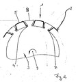
- FIG. 1 shows a perspective and incomplete representation of a driver unit 1.
- Fig. 1 shows no means for axially biasing the drive plate 3.
- Shown are only a drive plate 3 and, for example, an outer disc carrier 2.
- the drive plate 3 is equipped with a circumferential outer toothing 4.
- the outer disk carrier 2 has an internal toothing 5.
- the outer disk carrier 2 in the region of each tooth 6 on a slot-like recess 7, wherein each slot-like recess in the assembled state is penetrated in each case by a tooth 8 of the external toothing 4. Due to the special design of the teeth 8 and the slot-like recesses 7 Hintergreifung external teeth 4 and internal teeth 5 is achieved.
- the illustrated embodiment of the positive connection between the drive plate and plate carrier is shown only by way of example.
- the invention can also be implemented with differently shaped positive connections. It is sufficient, for example, an outer toothing on the circumference of the drive plate 3, which is received in recesses of the disk carrier. A special rear grip, or for example the provision of an internal toothing on the plate carrier are not absolutely necessary.
- a driver unit is indicated in the mounted state, wherein also here no means for axial prestressing of the drive plate 3 are located. It becomes clear that the driver disk 3 and the disk carrier 2 in the mounted state have a common axis of rotation 9.
- the positive connection between the drive plate 3 and outer plate carrier 2 is formed by an external toothing 4 on the drive plate 3 and an internal toothing 5 on the plate carrier 2, wherein the teeth 8 of the external teeth 4 engage in slot-like recesses 7 of the plate carrier 2.
- external teeth 4 and internal teeth 5 engage behind.
- the corrugated non-positive connection is only to be understood as an example. In a much simpler embodiment, no internal toothing is provided and the external toothing 4 is received in recesses in the plate carrier 2.
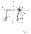
- Fig. 3 shows a schematic representation of a driver unit 1, consisting of a plate carrier 2 with outer plates, not shown, and a drive-side drive plate 3.
- the drive plate 3 is circumferentially positively connected to the outer plate carrier 2.
- teeth 8 of the drive plate 3 engage in slot-like recesses 7 in the plate carrier 2.
- the drive plate is supported in the axial direction at the end 10 of the slot-like recess 7 on the plate carrier 2.
- On the opposite side is provided as a means 11 for axially biasing a corrugated locking ring 12.
- the corrugated retaining ring 12 is formed circumferentially and in turn is supported on the plate carrier 2 in a Sich ceremoniessringnut 13 from.
- the circlip groove 13 is in the Lamella carrier 2 introduced circumferentially.
- a Sich ceremoniessringnut 13 for receiving a conventional locking ring 15 is shown.
- a radial force F R results in a bending moment M.
- the radial force F R is due for example to a not exactly aligned installation of the power transmission unit in the drive train.
- From the bending moment M results in an axial force F a , due to which the drive plate 3 would like to move in the axial direction.
- the axial force F a is compensated.
- the corrugated retaining ring 12 is interpreted as meaning that the axial force Fa due to the bending moment M is always smaller than the biasing force. Only then is a "lifting" of the drive plate 3 prevented.
- the frictional force generated in the circumferential direction with the biasing force must be large enough to prevent movement of the drive plate in the circumferential direction at least at low torques.
- a corrugated locking ring 12 as a means 11 for axial prestressing a significant advantage, since the previously necessary thickness moderately stepped locking rings can be replaced by a single, corrugated ring. Depending on the tolerance situation, up to 11 different thickness gradations were necessary. This tolerance compensation is now taken over by a single, corrugated ring within the spring travel.
- a plate spring 14 is provided in the driver unit 1 shown in Fig. 4, consisting of plate carrier 2 and drive plate 3 is as a means 11 for axially biasing the drive plate 3 against the plate carrier 2 at least a plate spring 14 is provided.
- the plate spring 14 is supported on the left side against the drive plate 3 from. With its right side, the plate spring 14 is supported on the plate carrier 2 via a securing ring 15.
- the securing ring 15 is held in a retaining ring groove 13 in the disk carrier 2.
- the drive plate 3 is mounted on the drive side.
- the driving force is introduced via a hub 16 in the drive plate 3 and transmitted via the positive connection in the plate carrier 2. Hub 16, Mitauerieri3 and plate carrier 2 have a common axis of rotation. 9
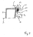
- a driver unit 1 consisting of disc carrier 2 and drive plate 3 is shown.
- the means 11 for axially biasing the drive plate 3 against the plate carrier 2 are formed as resilient tabs 17. With their free end, the tabs 17 are supported on a locking ring 15 in a Sich ceremoniessringnut 13 on the plate carrier. Over the circumference of the drive plate 3, a plurality of tabs 17 are arranged distributed.
- the one-piece construction results in particular advantages in the assembly. Also, the one-piece design leads to a considerable saving in material and manufacturing costs.
Claims (4)
- Dispositif d'entraînement, à utiliser dans des ensembles de transmission de force, en particulier dans des accouplements à lamelles ou des freins à friction, se composant d'un plateau d'entraînement et d'un support de lamelles, dans lequel le plateau d'entraînement est assemblé en complémentarité de forme avec le support de lamelles, caractérisé en ce que l'on prévoit, comme moyens (17) pour précharger axialement le plateau d'entraînement (3) contre le support de lamelles (2), des lames élastiques (17) qui sont formées d'un seul tenant avec le plateau d'entraînement (3).
- Dispositif d'entraînement selon la revendication 1, caractérisé en ce que le plateau d'entraînement (3) est pourvu d'une denture extérieure (4), et le support de lamelles (2) est pourvu d'une denture intérieure (5) de forme complémentaire au moins localement à la denture extérieure (4) du plateau d'entraînement (3), et dans lequel le plateau d'entraînement (3) peut être introduit dans le support de lamelles (2).
- Dispositif d'entraînement selon l'une quelconque des revendications précédentes, caractérisé en ce qu'il est prévu au moins une lame élastique (17), qui s'appuie d'une part sur le plateau d'entraînement (3) et d'autre part sur le support de lamelles (2), en particulier au moyen d'une bague de fixation (15) prévue dans une rainure de bague de fixation (13) dans le support de lamelles (2).
- Dispositif d'entraînement selon la revendication 3, caractérisé en ce qu'il est prévu plusieurs lames élastiques (17) réparties sur la périphérie du plateau d'entraînement (3).
Priority Applications (7)
| Application Number | Priority Date | Filing Date | Title |
|---|---|---|---|
| EP04009398A EP1589244B1 (fr) | 2004-04-21 | 2004-04-21 | Dispositif d'entraînement avec plateau d'entraînement préchargé axiallement |
| DE502004005130T DE502004005130D1 (de) | 2004-04-21 | 2004-04-21 | Mitnehmereinheit mit axial vorgespannter Mitnehmerscheibe |
| JP2007508814A JP2007533930A (ja) | 2004-04-21 | 2005-04-18 | 波形の止め輪付きパワー伝達装置 |
| EP05742774A EP1738088A1 (fr) | 2004-04-21 | 2005-04-18 | Ensemble de transfert de force a bague d'arret ondulee |
| US11/587,069 US20080011571A1 (en) | 2004-04-21 | 2005-04-18 | Force-Transmitting Assembly |
| PCT/EP2005/004094 WO2005103519A1 (fr) | 2004-04-21 | 2005-04-18 | Ensemble de transfert de force a bague d'arret ondulee |
| KR1020067023894A KR20070012482A (ko) | 2004-04-21 | 2005-04-18 | 파형 리테이닝 링을 구비한 힘전달 유닛 |
Applications Claiming Priority (1)
| Application Number | Priority Date | Filing Date | Title |
|---|---|---|---|
| EP04009398A EP1589244B1 (fr) | 2004-04-21 | 2004-04-21 | Dispositif d'entraînement avec plateau d'entraînement préchargé axiallement |
Publications (2)
| Publication Number | Publication Date |
|---|---|
| EP1589244A1 EP1589244A1 (fr) | 2005-10-26 |
| EP1589244B1 true EP1589244B1 (fr) | 2007-10-03 |
Family
ID=34924673
Family Applications (2)
| Application Number | Title | Priority Date | Filing Date |
|---|---|---|---|
| EP04009398A Expired - Lifetime EP1589244B1 (fr) | 2004-04-21 | 2004-04-21 | Dispositif d'entraînement avec plateau d'entraînement préchargé axiallement |
| EP05742774A Withdrawn EP1738088A1 (fr) | 2004-04-21 | 2005-04-18 | Ensemble de transfert de force a bague d'arret ondulee |
Family Applications After (1)
| Application Number | Title | Priority Date | Filing Date |
|---|---|---|---|
| EP05742774A Withdrawn EP1738088A1 (fr) | 2004-04-21 | 2005-04-18 | Ensemble de transfert de force a bague d'arret ondulee |
Country Status (6)
| Country | Link |
|---|---|
| US (1) | US20080011571A1 (fr) |
| EP (2) | EP1589244B1 (fr) |
| JP (1) | JP2007533930A (fr) |
| KR (1) | KR20070012482A (fr) |
| DE (1) | DE502004005130D1 (fr) |
| WO (1) | WO2005103519A1 (fr) |
Families Citing this family (7)
| Publication number | Priority date | Publication date | Assignee | Title |
|---|---|---|---|---|
| FR2881196B1 (fr) * | 2005-01-27 | 2007-03-16 | Renault Sas | Systeme d'embrayage humide multiple comprenant un flasque d'entrainement a languettes de centrage |
| WO2007124709A1 (fr) * | 2006-04-28 | 2007-11-08 | Luk Lamellen Und Kupplungsbau Beteiligungs Kg | Dispositif de disque a embrayage |
| DE202007010294U1 (de) | 2007-07-20 | 2008-11-27 | Wirtgen Gmbh | Baumaschine sowie Schaltkupplung zum Schalten des Kraftflusses |
| EP2246584B1 (fr) * | 2009-04-27 | 2014-01-01 | Transmisiones y Equipos Mecánicos, S.A. de C.V. | Embrayage |
| DE102010044379A1 (de) * | 2010-09-04 | 2012-03-08 | Volkswagen Ag | Kupplung |
| DK178917B1 (da) | 2016-05-31 | 2017-05-22 | Kadicma Aps | Bajonetkobling samt bearbejdningsenhed med sådan bajonetkobling |
| CN114198421B (zh) * | 2021-11-19 | 2024-01-12 | 吉利长兴自动变速器有限公司 | 一种湿式离合器 |
Family Cites Families (12)
| Publication number | Priority date | Publication date | Assignee | Title |
|---|---|---|---|---|
| DE886833C (de) * | 1951-05-26 | 1953-08-17 | Hubert Flamang | Stellring |
| DE1450101A1 (de) * | 1964-06-30 | 1969-07-10 | Daimler Benz Ag | Federnde Abstuetzung von Kupplungslamellen |
| DE2125870B2 (de) * | 1971-05-25 | 1975-09-11 | Zf Getriebe Gmbh, 6600 Saarbruecken | Lamellentrager |
| US4752178A (en) * | 1986-12-17 | 1988-06-21 | Smalley Steel Ring Company | Waved retaining ring |
| US4982620A (en) * | 1988-04-29 | 1991-01-08 | Chrysler Corporation | Method of learning for adaptively controlling an electronic automatic transmission system |
| JPH0756328B2 (ja) * | 1990-10-29 | 1995-06-14 | 株式会社大金製作所 | トルクコンバータ用ロックアップ装置 |
| JP3447346B2 (ja) * | 1993-11-15 | 2003-09-16 | Nskワーナー株式会社 | ワンウェイクラッチの外輪の固定構造 |
| JP3537597B2 (ja) * | 1996-07-05 | 2004-06-14 | ジヤトコ株式会社 | 動力伝達部のスプライン結合構造 |
| US5906255A (en) * | 1997-06-18 | 1999-05-25 | Deltrans, Inc. | Automatic transmission clutch drum assembly with waved ring spring |
| DE10004195B4 (de) * | 1999-09-30 | 2013-02-07 | Volkswagen Ag | Mehrfach-Kupplungseinrichtung |
| JP4211205B2 (ja) * | 2000-07-24 | 2009-01-21 | 株式会社ジェイテクト | クラッチ装置 |
| DE50213480D1 (de) * | 2002-06-15 | 2009-06-04 | Borgwarner Inc | Mitnehmerscheibe für Lamellenkupplungssysteme |
-
2004
- 2004-04-21 EP EP04009398A patent/EP1589244B1/fr not_active Expired - Lifetime
- 2004-04-21 DE DE502004005130T patent/DE502004005130D1/de not_active Expired - Lifetime
-
2005
- 2005-04-18 EP EP05742774A patent/EP1738088A1/fr not_active Withdrawn
- 2005-04-18 US US11/587,069 patent/US20080011571A1/en not_active Abandoned
- 2005-04-18 KR KR1020067023894A patent/KR20070012482A/ko not_active Application Discontinuation
- 2005-04-18 WO PCT/EP2005/004094 patent/WO2005103519A1/fr active Application Filing
- 2005-04-18 JP JP2007508814A patent/JP2007533930A/ja active Pending
Also Published As
| Publication number | Publication date |
|---|---|
| DE502004005130D1 (de) | 2007-11-15 |
| KR20070012482A (ko) | 2007-01-25 |
| US20080011571A1 (en) | 2008-01-17 |
| EP1589244A1 (fr) | 2005-10-26 |
| WO2005103519A1 (fr) | 2005-11-03 |
| JP2007533930A (ja) | 2007-11-22 |
| EP1738088A1 (fr) | 2007-01-03 |
Similar Documents
| Publication | Publication Date | Title |
|---|---|---|
| EP3139053B1 (fr) | Double embrayage dote d'un piston vertical et de butees d'embrayage ameliorees | |
| DE102008063662A1 (de) | Lamelle für eine reibschlüssig arbeitende Einrichtung und reibschlüssig arbeitende Einrichtung mit einer solchen Lamelle | |
| WO2007118441A2 (fr) | Dispositif permettant d'amortir les vibrations d'une roue motrice destinée à entraîner une unité secondaire d'un véhicule automobile | |
| EP1381788B1 (fr) | Engrenage avec liaison sans cliquetis entre cloche d'embrayage et plateau d'entrainement | |
| WO2005103519A1 (fr) | Ensemble de transfert de force a bague d'arret ondulee | |
| DE102004008538B4 (de) | Differential mit einer Bolzenbefestigungsbaugruppe | |
| DE102008011914B4 (de) | Vorspanneinheit | |
| DE102011003030B4 (de) | Kupplungsscheibe für eine Reibungskupplung eines Kraftfahrzeugs | |
| DE102007062363A1 (de) | Schaltgetriebe | |
| DE102017119079A1 (de) | Doppelschlingfeder, Rotationseinrichtung und zu aktuierendes System | |
| DE102008014445A1 (de) | Kopplungsanordnung mit Federeinrichtung, Federeinrichtung für eine solche Kopplungsanordnung und Antriebsstrang für ein Kraftfahrzeug mit einer solchen Kopplungsanordnung | |
| DE102006055220B4 (de) | Kraftübertragungsaggregat mit zwei drehbaren Bauteilen | |
| EP1899628A1 (fr) | Unite d'entrainement par engrenages | |
| DE102008022865A1 (de) | Kupplungsvorrichtung mit einer eingangsseitigen Kopplungseinrichtung und Verwendung eines Zahnrades mit zwei Teilrädern zur Ausbildung einer Steckverzahnung | |
| DE102007015104A1 (de) | Kopplungseinrichtung und Kupplungsanordnung mit einer solchen Kopplungseinrichtung | |
| DE102010006472A1 (de) | Drehmomentübertragungseinrichtung | |
| DE102011006028A1 (de) | Sicherungselement für Doppelkupplung | |
| EP1460303A1 (fr) | Amortisseur de vibrations de torsion | |
| DE102022110823B3 (de) | Nabe mit einer Rotationsachse für eine verzahnte Welle-Nabe-Verbindung | |
| DE102018124338A1 (de) | Reiblamelle | |
| DE202017101823U1 (de) | Tonnenkupplung, insbesondere für eine Seiltrommelgelenkverbindung eines Hubwerks | |
| DE102017121135A1 (de) | Verfahren zur Montage zumindest eines Kupplungsbolzens in einer Kupplungsanordnung für ein Wellgetriebe, Kupplungsanordnung für ein Wellgetriebe und Kupplungsbolzen zur Verwendung in einer Kupplungsanordnung für ein Wellgetriebe | |
| DE10162396B4 (de) | Antriebsstrang für Kraftfahrzeuge | |
| DE102021213313A1 (de) | Welle-Nabe-Verbindung | |
| DE102021211647A1 (de) | Welle-Nabe-Verbindung |
Legal Events
| Date | Code | Title | Description |
|---|---|---|---|
| PUAI | Public reference made under article 153(3) epc to a published international application that has entered the european phase |
Free format text: ORIGINAL CODE: 0009012 |
|
| AK | Designated contracting states |
Kind code of ref document: A1 Designated state(s): AT BE BG CH CY CZ DE DK EE ES FI FR GB GR HU IE IT LI LU MC NL PL PT RO SE SI SK TR |
|
| AX | Request for extension of the european patent |
Extension state: AL HR LT LV MK |
|
| RAP1 | Party data changed (applicant data changed or rights of an application transferred) |
Owner name: BORGWARNER INC. |
|
| 17P | Request for examination filed |
Effective date: 20060204 |
|
| AKX | Designation fees paid |
Designated state(s): DE FR GB IT |
|
| 17Q | First examination report despatched |
Effective date: 20060418 |
|
| GRAP | Despatch of communication of intention to grant a patent |
Free format text: ORIGINAL CODE: EPIDOSNIGR1 |
|
| GRAS | Grant fee paid |
Free format text: ORIGINAL CODE: EPIDOSNIGR3 |
|
| GRAA | (expected) grant |
Free format text: ORIGINAL CODE: 0009210 |
|
| AK | Designated contracting states |
Kind code of ref document: B1 Designated state(s): DE FR GB IT |
|
| REG | Reference to a national code |
Ref country code: GB Ref legal event code: FG4D Free format text: NOT ENGLISH |
|
| REF | Corresponds to: |
Ref document number: 502004005130 Country of ref document: DE Date of ref document: 20071115 Kind code of ref document: P |
|
| GBV | Gb: ep patent (uk) treated as always having been void in accordance with gb section 77(7)/1977 [no translation filed] | ||
| EN | Fr: translation not filed | ||
| PLBE | No opposition filed within time limit |
Free format text: ORIGINAL CODE: 0009261 |
|
| STAA | Information on the status of an ep patent application or granted ep patent |
Free format text: STATUS: NO OPPOSITION FILED WITHIN TIME LIMIT |
|
| 26N | No opposition filed |
Effective date: 20080704 |
|
| PG25 | Lapsed in a contracting state [announced via postgrant information from national office to epo] |
Ref country code: FR Free format text: LAPSE BECAUSE OF FAILURE TO SUBMIT A TRANSLATION OF THE DESCRIPTION OR TO PAY THE FEE WITHIN THE PRESCRIBED TIME-LIMIT Effective date: 20080718 |
|
| PG25 | Lapsed in a contracting state [announced via postgrant information from national office to epo] |
Ref country code: GB Free format text: LAPSE BECAUSE OF FAILURE TO SUBMIT A TRANSLATION OF THE DESCRIPTION OR TO PAY THE FEE WITHIN THE PRESCRIBED TIME-LIMIT Effective date: 20071003 |
|
| PG25 | Lapsed in a contracting state [announced via postgrant information from national office to epo] |
Ref country code: IT Free format text: LAPSE BECAUSE OF NON-PAYMENT OF DUE FEES Effective date: 20080430 |
|
| PGFP | Annual fee paid to national office [announced via postgrant information from national office to epo] |
Ref country code: DE Payment date: 20190318 Year of fee payment: 16 |
|
| REG | Reference to a national code |
Ref country code: DE Ref legal event code: R119 Ref document number: 502004005130 Country of ref document: DE |
|
| PG25 | Lapsed in a contracting state [announced via postgrant information from national office to epo] |
Ref country code: DE Free format text: LAPSE BECAUSE OF NON-PAYMENT OF DUE FEES Effective date: 20201103 |