EP1588947A2 - Vorrichtung zum Umhüllen von Gruppen von Gegenständen mit einem Stretchfolienschlauch - Google Patents
Vorrichtung zum Umhüllen von Gruppen von Gegenständen mit einem Stretchfolienschlauch Download PDFInfo
- Publication number
- EP1588947A2 EP1588947A2 EP05425250A EP05425250A EP1588947A2 EP 1588947 A2 EP1588947 A2 EP 1588947A2 EP 05425250 A EP05425250 A EP 05425250A EP 05425250 A EP05425250 A EP 05425250A EP 1588947 A2 EP1588947 A2 EP 1588947A2
- Authority
- EP
- European Patent Office
- Prior art keywords
- film
- machine according
- carousel
- bars
- station
- Prior art date
- Legal status (The legal status is an assumption and is not a legal conclusion. Google has not performed a legal analysis and makes no representation as to the accuracy of the status listed.)
- Granted
Links
Images





Classifications
-
- B—PERFORMING OPERATIONS; TRANSPORTING
- B65—CONVEYING; PACKING; STORING; HANDLING THIN OR FILAMENTARY MATERIAL
- B65B—MACHINES, APPARATUS OR DEVICES FOR, OR METHODS OF, PACKAGING ARTICLES OR MATERIALS; UNPACKING
- B65B21/00—Packaging or unpacking of bottles
- B65B21/24—Enclosing bottles in wrappers
- B65B21/245—Enclosing bottles in wrappers in flexible wrappers, e.g. foils
-
- B—PERFORMING OPERATIONS; TRANSPORTING
- B65—CONVEYING; PACKING; STORING; HANDLING THIN OR FILAMENTARY MATERIAL
- B65B—MACHINES, APPARATUS OR DEVICES FOR, OR METHODS OF, PACKAGING ARTICLES OR MATERIALS; UNPACKING
- B65B9/00—Enclosing successive articles, or quantities of material, e.g. liquids or semiliquids, in flat, folded, or tubular webs of flexible sheet material; Subdividing filled flexible tubes to form packages
- B65B9/10—Enclosing successive articles, or quantities of material, in preformed tubular webs, or in webs formed into tubes around filling nozzles, e.g. extruded tubular webs
- B65B9/13—Enclosing successive articles, or quantities of material, in preformed tubular webs, or in webs formed into tubes around filling nozzles, e.g. extruded tubular webs the preformed tubular webs being supplied in a flattened state
- B65B9/14—Devices for distending tubes supplied in the flattened state
Definitions
- the present invention addresses the sector of packaging groups of products by wrapping them in tubular film lengths.
- This invention relates in particular to the sector of packaging with stretch film, where the film is not heated but applied cold, stretched over the groups of products to be wrapped and left to return to its original size, thanks to its elastic properties, to form individual packs in which the products are held together tightly.
- machines for stretch wrapping groups of products are well known. These machines typically comprise several operating stations designed to receive groups of products and to wrap each group with a length of stretch film.
- patent IT1285827 to the same Applicant as the present discloses a machine and a method for wrapping groups of products in tubular stretch film lengths.
- the machine described in that patent comprises a station for feeding tubular film lengths to a stretching device where a set of reciprocally mobile parallel rods engage the tube of film lengthways.
- the stretching device After receiving the film, the stretching device moves towards a placing station and, while doing so, stretches the tube of film to the size and shape matching that of the group of products waiting to be wrapped at the placing and unloading station.
- the group of products is inserted into the tube which, on being released by the bars, tends to return to its original size over the group of products in such a way as to form a pack which is then unloaded.
- this type of machine has a revolver-like structure comprising a plurality of stretching devices arranged in a circle and made to move one after the other first through the feed station and then through the placing and unloading station.
- a machine designed in this way has the advantage of offering high productivity in a limited space and making a continuous flow of packages whose formation is synchronised with the feeding of the film tubes to the placing station and hence with the speed of carousel rotation.
- a first aim of the present invention is to overcome the above mentioned disadvantage by providing a high productivity machine with a relatively simple structure.
- the advantages achieved consist essentially in reducing the number of actuators necessary for fully stretching the film and, in particular, the number of actuators that move with the carousel.
- Another advantage is the possibility of using more powerful actuators without increasing the weight to be moved.
- the stretching bars may be advantageously guided in the vertical direction by straight guides and/or guides with cam-like profile, extending for the whole or part of the circumference of the carousel and engaged directly or indirectly with the bars that move with the carousel.
- an active contribution to the stretching of the film may also be provided by the guide profiles acting in conjunction with the rotation of the carousel. This makes it possible to reduce the number of actuators necessary for stretching and positioning the bars (and the length of film) during operations.
- Yet another advantageous feature of a machine according to the appended claims is the possibility of having at least two carousels connected, for example, by a conveyor belt so that a group of products can be wrapped successively by two (or more) lengths of film at a defined angle from each other, thus improving the stability of the package.
- the outer wrap can be used to make a handle by which the package can be carried.
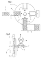
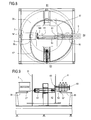
- a machine according to the invention for wrapping groups of products 7 in tubular lengths stretch film 4 comprises a rotating carousel structure 1 mounted on a base B on a rack 16 which may be rotationally driven about a vertical axis by a motor M1 connected to the rack 16 by a toothed belt 17.
- the carousel is driven by a brushless motor which acts on the belt 17.
- this improves the adaptability of the machine since the start-stop motion of the carousel can be varied according to the size of the products to be wrapped.
- the brushless motor and belt drive system might be substituted by an inverter device controlling a kinematic chain consisting of an intermitter meshed directly with rack through a gear.
- This embodiment is less adaptable but simpler and more rigid, which means it may be preferable when the machine is always used for products of the same type and size.
- the carousel is equipped with two or more wrapping units 2 (in the embodiment being described there are four of them but in other embodiments there may be a different number of them, such as for example, three) which rotate as one with the carousel and are preferably spaced at equal angular intervals of 90° around the circumference of the carousel 1.
- the unit 5, shown in Figure 1 but not described in detail because it does not as such form part of the invention, may be of the type capable of forming tubular film lengths either from continuous rollfed plane webs of film that are cut and sealed to form individual tubes, or from a continuous film that is already tubular in shape and must be simply cut into the required lengths.
- the unit 5 after forming the tubular film length 4, feeds the length of film to the wrapping unit 2 at the station S1.
- the unit 5 preferably comprises suction cups for holding the film and transferring the lengths 4 radially from the unit 5 to the wrapping unit 2.
- the unit 5 comprises a transfer unit having arms equipped with suction cups which pick up the length of film from the unit 5 and fit it on the stretch bars at the feed station, in synchrony with the rotation of the carousel.
- a machine according to the invention further comprises:
- the steps of feeding each tubular film length 4, stretching the film, loading the products 7 and unloading the wrapped packages 8 are performed simultaneously at the respective stations S1-S4 during the stops in the intermittent rotation of the carousel 1.
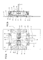
- the wrapping units 2 are each preferably equipped with a plate 31 connected at the top and bottom by a cross 40 and a ring-shaped base 41 together forming a drum 47 (shown in Figure 1a) that turns on the rack 16.
- the base 41 constitutes a support on which the drum 47 is built, whilst the plates 31 are connected by gussets or reinforcements and corner pieces, not illustrated, while the upper cross 40 joins the top of the drum 47 and acts as a counter-rotating element for a rotary power supply distributor 60.
- Two carriages 20 can run up and down on the plates 31 along vertical guides 37, each of said carriages being in turn equipped with two horizontal guides 25 positioned in line with each other, on which there run respective carriages 11, each driven by an independent actuator, preferably pneumatic.
- each actuator may consist of a pneumatic cylinder 32 attached at one end to a fixed point 35 of the respective carriage 20 and at the other end to a lever 33 pivoted on a pin 36; the lever 33 being connected at its opposite end to a connecting rod 34 that drives the carriage 11.
- the two carriages 20 respectively support the upper and lower pairs of the four stretch bars 3, whilst the horizontal motion of each of the bars 3 may be independent and follows the respective carriage 11.
- the movement of the individual carriage 11 is controlled by a position detector preferably at least consisting of a sensor mounted on the carriage 11 and which detects a signal while moving along a magnetic bar fixed to the carriage 20. This signal is then passed to an electronic system that converts it into a value representing the position of the carriage on the guide 25.
- a position detector preferably at least consisting of a sensor mounted on the carriage 11 and which detects a signal while moving along a magnetic bar fixed to the carriage 20.
- This signal is then passed to an electronic system that converts it into a value representing the position of the carriage on the guide 25.
- numeric control system to follow and control the movement of the carriages 11 using, for example, an optical system (encoder) mounted at the fulcrum of the lever 33 and designed to read the rotations of the lever and hence the movement of each carriage 11.
- the electrical signal detected in this way is also used to control the pneumatic actuator 32 by stopping the piston stem when the bar 3 reaches the predetermined position.
- both the control systems and the drive systems of the individual bars 3 are independent of each other, it is possible to create many different configurations, even non symmetrical ones, depending on the geometry of the products to be wrapped or on the properties of the film used, in order to optimise both the power required to stretch the film and the mechanical behaviour of the film after being stretched.
- the bars 3 are mounted in pairs on two vertically mobile carriages 20 equipped with two pins 21 that slide in slots 38 in the plates 31.
- the pins 21 can engage with matching mobile sockets 42 fixed by plates 43 to vertical toothed belts 44 driven by respective actuators 15 in such a way that they can run up and down on a straight guide 45 attached to a fixed wall 46.
- the vertical actuators might be linear actuators 12', consisting, for example, of two recirculating ball screws 51 mounted vertically and rotationally driven by respective motors M2, M3.
- the vertical movement of the bars 3 is also controlled by proximity sensors 58 mounted at the working positions.
- the mobile sockets 42 form part of a set of guides, labelled 13 in their entirety, for moving the pins 21 and extending along the outer walls of a fixed turret structure 47 mounted at the centre of the carousel 1, the above mentioned wall 46 forming the part of it corresponding to the stretching station S2.
- the set of guides 13 comprises:
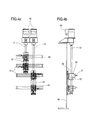
- the rails in the section T4 can be moved vertically by a pair of screws, which are driven by independent motors 50 and which engage with matching lead nuts 52, the latter being attached to the rails 53 and slidable on vertical guides 55 fixed to a wall 66 of the fixed turret 4. Described below with reference to Figures 4 and 5 are the positions adopted by the stretch bars 3 in the successive operating steps.
- the bars 3 are positioned at the station S1 at a distance from each other such that they can receive the film length 4 and then move apart slightly so that they can hold the film securely while they are moved in a horizontal direction by the actuators acting on the carriages 11.
- each unit 2 again by means of the horizontal actuators, starts stretching the film 4 in horizontal direction until it is at least as wide as the group of products to be wrapped.
- the bars 3 are independent of each other so that the lower pair of bars 3 may, depending on the geometry of the products to be wrapped, be moved apart by an amount greater or smaller than the upper pair of bars 3 (in the example shown in Figure 5, they are further apart).
- the carousel 1 stops and, during this stop, the vertical actuators 15 fully stretch the tubular film lengths 4 to size (step F3).
- the pins 21 are engaged in the mobile sockets 42 guided by the vertical guides 45 and driven by the actuators 15.
- the actuators 15 preferably operate on the upper and lower pairs of bars 3 symmetrically in such a way as to stretch the film uniformly about a central geometrical plane 14'.
- the vertical stretching means are fixed at the stretching station S2 where most of the stretching operation is carried out, thus concentrating the power required for stretching and reducing the weight to be carried by the carousel.
- the actuators 32/15 that cause the film to be stretched are controlled electronically so that the stretching of the film by suitable laws of motion can be optimised according to film properties so as to avoid tearing and irregular thickness (stretching controlled in terms of speed and position).
- the bars 3 consist of idle rollers, preferably covered with non-stick material.
- the film is stretched in particularly even fashion, minimising the risk of tearing and deformation of the film lengths.
- suction cups are provided to apply a sideways pulling action on the film length in such a way as to create surface friction between the film and the rollers at least at the moment stretching starts, thus forcing all the rollers to turn and preventing the length of film from being stretched non-uniformly.
- the suction cups prevent individual idle rollers from sticking which, besides causing the film to be distributed evenly, also makes it possible to centre any images printed on the film itself.
- the suction cups prevent the film from rotating relative to the rollers as a result of the stretching action, keeping the sealing line in a fixed position, for example always under the loading table and centred in relation to the products.
- the centring step F4 may be dispensed with by providing a loading table 14 that can move to and fro between a retracted position within the radial dimensions of the bars 3, corresponding to the feed station S1 and the stretching station S2, and an advanced position corresponding to the loading and unloading positions at the stations S3, S4.
- the to and fro movement of the table 14 may be achieved by a fixed flat cam 57' which is located on a supporting surface 58 and which engages with a pin 59 on the underside of the table 14 so that the latter follows the cam profile as the carousel 1 rotates.
- the table is out of the way when the film is being fed so that pins, without the interference of the table 14, can be closer together, the table 14 only appears when the product is loaded.
- a pusher 60 for unloading the packages 8 from the carousel may be provided, mounted in the column 47 and driven by a linear actuator, for example of the type with a lead nut 61, attached to the pusher and moved by a recirculating ball screw 62 powered by a motor M5.
- step F4 the carousel 1 continues rotating until the film length 4 is positioned at the station S3 where the groups of products 7 are placed inside the film length 4 (step F5).
- the feeding of the product groups 7 is accomplished by a belt 9 equipped with pushers 22 designed to push the groups 7 on the loading table 14 into the waiting film length 4, but it will be understood that equivalent feed means of a different type might also be used.
- the bars 3 are positioned in such a way as to guide the bottles, which are narrower at the top, into the film length 4.
- the pin 21 which controls the vertical movement of the upper pair of bars 3 enters a vertical sector and moves down by a predetermined amount such as to make the film 4 come into contact with the top surface of the group of products 7.
- presser plates 23, which move as one with the units 2 and are driven vertically by the actuators 24, may be used to move down onto the package 8 in such a way as to further stabilise it while it is being transferred to the unloading station.
- the pins 21 are engaged in the converging section T3 of the set of guides 13 so that the bars 3 follow the profile T3 of the guides 13, thus moving closer together until they reach a position where they are extracted from the package 8 (step F6) at the unloading station S4.
- the carousel stops and the package 8 is unloaded from the carousel onto a conveyor 10 by an ejection element that is not described in detail because it is of customary type.
- step F7 After unloading at the station S4, the carousel 1 starts rotating again and the pins 21 are engaged in the mobile horizontal sectors 57 of the section T4 of the set of guides 13 and are moved by the actuator 50 along the vertical guides 55 (step F7) so that the bars 3 move closer together in the vertical direction until they are once again centred relative to the loading table 14 and at the height they started from in step F1.
- the bars 3, driven by the carriages 11, move closer together also in the horizontal direction and return to the feed station S1 to the position they started from in step F1, ready to receive the next film length 4 when the carousel 1 next stops.
- the set of guides 13 is designed not only to guide the movement of the carriages 20 but also to cause their vertical movement, either substituting or acting in conjunction with the actuators 15.
- the pins 21 of the carriages 20 are constrained by the rotation of the carousel 1 to follow the profile of the fixed guides 13, thus driving the bars 3 with the film length 4 on them, and either produce the sole vertical stretching action or contribute to the stretching action.
- this solution is particularly useful for small sized products that require less stretching power and makes it possible to eliminate at least the vertical actuators, or reduce their number, thus simplifying and further lightening the machine structure.
- the embodiment of the invention illustrated in Figure 6 is an installation for wrapping groups of products in lengths of tubular film comprising an additional machine 1' of the type described above connected by a conveyor belt 26 to a machine 1 operating in the manner described above.
- the conveyor 26 transfers to the placing station S3' of the second machine 1' a succession of packaged groups 8 that are turned about a vertical axis by 90° relative to the position in which they were fed to the placing station S3 of the first machine 1.
- This embodiment advantageously applies the tubular film lengths to the products in crossed fashion.
- the two carousels are set at 90° so that the direction of the packages 8' feeding out of the second carousel is at right angles to the direction of the groups of products 7 fed into the first carousel.
- the two carousels might also be arranged in such a way as to create an in line configuration, for example by using a differently oriented conveyor 10 or by changing the direction of rotation of the carousels so as to change the relative position of the stations.
- the station S1' for feeding the product packages 8 to the second machine 1' may comprise a unit 28 for forming a handle from the upper portion of the second film length 4'.
- the unit 28 is equipped with a gripper 29 which, after the package 8 has been inserted into the film length 4' and before, or at the same time as, this film length is allowed to shrink onto the package 8, grips the top portion of the film length 4' and gathers it up like a strap.
- Friction causes the film to remain in the gathered up state on the surface of the upper bars 3, thus forming a handle 30 by which the pack can be carried.
- the movements of the bars 3, guided by the guides 13 or driven directly by the actuators 15 can be varied in order to make the most of the shape and size of the products to be wrapped.
- the tapering geometry of the bottle necks forms a cavity between the two rows of bottles which makes it easier to create a handle 30 that is easy to grip (Figure 7).
- the bars 3 may follow at least part of the outer profile of the product groups so that the film adheres better to the products and thus improving the stability of the packages.
Landscapes
- Engineering & Computer Science (AREA)
- Mechanical Engineering (AREA)
- Basic Packing Technique (AREA)
- Shaping By String And By Release Of Stress In Plastics And The Like (AREA)
Applications Claiming Priority (2)
| Application Number | Priority Date | Filing Date | Title |
|---|---|---|---|
| IT000253A ITBO20040253A1 (it) | 2004-04-23 | 2004-04-23 | Macchina per il confezionamento di gruppi di prodotti mediante spezzoni tubolari di film elastico |
| ITBO20040253 | 2004-04-23 |
Publications (3)
| Publication Number | Publication Date |
|---|---|
| EP1588947A2 true EP1588947A2 (de) | 2005-10-26 |
| EP1588947A3 EP1588947A3 (de) | 2005-12-14 |
| EP1588947B1 EP1588947B1 (de) | 2008-06-11 |
Family
ID=34943169
Family Applications (1)
| Application Number | Title | Priority Date | Filing Date |
|---|---|---|---|
| EP05425250A Expired - Lifetime EP1588947B1 (de) | 2004-04-23 | 2005-04-20 | Vorrichtung zum Umhüllen von Gruppen von Gegenständen mit einem Stretchfolienschlauch |
Country Status (5)
| Country | Link |
|---|---|
| US (1) | US7191574B2 (de) |
| EP (1) | EP1588947B1 (de) |
| DE (1) | DE602005007412D1 (de) |
| ES (1) | ES2308422T3 (de) |
| IT (1) | ITBO20040253A1 (de) |
Cited By (2)
| Publication number | Priority date | Publication date | Assignee | Title |
|---|---|---|---|---|
| WO2016096621A1 (en) * | 2014-12-16 | 2016-06-23 | Nestec S.A. | Pack of products comprising a handle |
| WO2016096620A1 (en) * | 2014-12-16 | 2016-06-23 | Nestec S.A. | Process and device for manufacturing a pack of products comprising a handle |
Families Citing this family (17)
| Publication number | Priority date | Publication date | Assignee | Title |
|---|---|---|---|---|
| ITBO20050630A1 (it) * | 2005-10-20 | 2007-04-21 | Kpl Packlaging S P A | Metodo e macchina per l'imballaggio di gruppi di prodotti ordinati su uno o piu' strati |
| US20110036055A1 (en) * | 2008-02-28 | 2011-02-17 | Uni-Charn Corporation | Pusher used in packaging equipment |
| JP5138626B2 (ja) * | 2009-03-27 | 2013-02-06 | 株式会社フジシールインターナショナル | フィルム供給装置 |
| US8695779B2 (en) | 2011-10-24 | 2014-04-15 | Remedi Technology Holdings, Llc | Packaging system for pharmaceutical dispenser and associated method |
| DE102011087729A1 (de) * | 2011-12-05 | 2013-06-06 | Krones Ag | Vorrichtung und Verfahren zum Etikettieren von Behältern mit elastischen Etikettenhülsen |
| DE102011087727A1 (de) * | 2011-12-05 | 2013-06-06 | Krones Ag | Vorrichtung und Verfahren zum Etikettieren von Behältern mit elastischen Etikettenhülsen |
| DE102011090107A1 (de) * | 2011-12-29 | 2013-07-04 | Krones Ag | Vorrichtung und Verfahren zum Etikettieren von Behältern mit Etikettenhülsen |
| US10611508B2 (en) * | 2014-01-23 | 2020-04-07 | Allen Plastic Industries Co., Ltd. | Sleeve labeling machine |
| ITUB20153017A1 (it) * | 2015-08-07 | 2017-02-07 | Bema Srl | Dispositivo per l'avvolgimento di prodotti |
| US11591121B2 (en) * | 2017-06-01 | 2023-02-28 | Illinois Tool Works Inc. | Compact applicating machine |
| CN109649722B (zh) * | 2018-12-27 | 2024-04-09 | 成都市德工思普瑞机器人有限公司 | 一种全自动酒瓶包膜机 |
| BE1027643B1 (de) * | 2019-10-09 | 2021-05-11 | Phoenix Contact Gmbh & Co | Technik zur Kennzeichnung eines prolaten Objekts |
| CN112317650B (zh) * | 2020-09-14 | 2022-09-13 | 岳阳高澜节能装备制造有限公司 | 一种线缆定长切断、套膜设备 |
| CN112191156B (zh) * | 2020-10-12 | 2022-11-29 | 澳优乳业(中国)有限公司 | 基于粉体物料包装整箱的自动混合系统及控制方法 |
| CN113184253B (zh) * | 2021-06-11 | 2022-08-02 | 安阳工学院 | 一种立卧交叉缠膜打包装置 |
| CN115783361A (zh) * | 2022-12-22 | 2023-03-14 | 成都宏明双新科技股份有限公司 | 一种全自动零件裹膜包装设备及方法 |
| CN118928891B (zh) * | 2024-10-14 | 2025-02-11 | 连云港创诚塑胶科技有限公司 | 一种t型轮毂保护圈用包装装置及方法 |
Family Cites Families (11)
| Publication number | Priority date | Publication date | Assignee | Title |
|---|---|---|---|---|
| US3479930A (en) * | 1967-09-05 | 1969-11-25 | Diamond Int Corp | Automatic stretch bag machine |
| FR2203354A5 (de) * | 1972-10-18 | 1974-05-10 | Thes Elephant Ste | |
| US4403463A (en) * | 1979-10-26 | 1983-09-13 | Danti Bernard R | Packaging in extensible bands |
| GB2087338B (en) * | 1980-11-11 | 1984-12-19 | Grace W R & Co | Apparatus and method for wrapping sausage or cheese in a fflexible wrapping material |
| US4514966A (en) * | 1982-12-02 | 1985-05-07 | Konstantin Anatole E | Shrink banding machine for use with thin film |
| EP0442111A3 (en) * | 1989-12-22 | 1991-09-25 | Officina Meccanica Sestese S.P.A. | Process to package loose objects, particularly bottles, machine to carry out said process, and transportable packaging obtained with said process |
| IT1285827B1 (it) | 1996-07-31 | 1998-06-24 | Robopac Sistemi Srl | Metodo ed apparecchiatura per l'avvolgimento di gruppi di prodotti con un film in materiale estensibile |
| DE50104188D1 (de) * | 2000-08-30 | 2004-11-25 | Ferag Ag | Verfahren und Vorrichtung zur Umreifung von Stapeln von Druckereierzeugnissen |
| EP1288127B1 (de) * | 2001-08-03 | 2005-10-26 | AETNA GROUP S.p.A. | Verfahren und Vorrichtung zum Umwickeln von gruppierten Gegenständen mit einer Stretchfolie |
| ITBO20010726A1 (it) * | 2001-11-27 | 2003-05-27 | Aetna Group Spa | Metodo per la realizzazione di una confezione di prodotti e apparecchiatura attuante tale metodo |
| ITBO20020768A1 (it) * | 2002-12-06 | 2004-06-07 | Aetna Group Spa | Apparecchiatura per la definizione di uno spezzone |
-
2004
- 2004-04-23 IT IT000253A patent/ITBO20040253A1/it unknown
-
2005
- 2005-04-20 EP EP05425250A patent/EP1588947B1/de not_active Expired - Lifetime
- 2005-04-20 DE DE602005007412T patent/DE602005007412D1/de not_active Expired - Lifetime
- 2005-04-20 ES ES05425250T patent/ES2308422T3/es not_active Expired - Lifetime
- 2005-04-22 US US11/112,887 patent/US7191574B2/en not_active Expired - Lifetime
Cited By (4)
| Publication number | Priority date | Publication date | Assignee | Title |
|---|---|---|---|---|
| WO2016096621A1 (en) * | 2014-12-16 | 2016-06-23 | Nestec S.A. | Pack of products comprising a handle |
| WO2016096620A1 (en) * | 2014-12-16 | 2016-06-23 | Nestec S.A. | Process and device for manufacturing a pack of products comprising a handle |
| US10435216B2 (en) | 2014-12-16 | 2019-10-08 | Societe Des Produits Nestle S.A. | Pack of products comprising a handle |
| US10730654B2 (en) | 2014-12-16 | 2020-08-04 | Societe Des Produits Nestle S.A. | Process and device for manufacturing a pack of products comprising a handle |
Also Published As
| Publication number | Publication date |
|---|---|
| US7191574B2 (en) | 2007-03-20 |
| US20050235613A1 (en) | 2005-10-27 |
| EP1588947B1 (de) | 2008-06-11 |
| DE602005007412D1 (de) | 2008-07-24 |
| ITBO20040253A1 (it) | 2004-07-23 |
| ES2308422T3 (es) | 2008-12-01 |
| EP1588947A3 (de) | 2005-12-14 |
Similar Documents
| Publication | Publication Date | Title |
|---|---|---|
| EP1588947B1 (de) | Vorrichtung zum Umhüllen von Gruppen von Gegenständen mit einem Stretchfolienschlauch | |
| US7712291B2 (en) | Film wrapping machine simultaneously utilizing two film carriage assemblies | |
| EP3580038B1 (de) | Anordnung zur herstellung von füllbaren behältern und verpackungslinie mit solch einer anordnung und entsprechendes verfahren | |
| CN101663202A (zh) | 使用两个薄膜载架组件以有效地执行薄膜更换操作的薄膜封装机 | |
| US20070289665A1 (en) | Container transportation line bottling plants | |
| WO2007137923A1 (en) | A machine for grouping packs | |
| JP2529721Y2 (ja) | 包装機械 | |
| JP5628740B2 (ja) | 袋詰め包装機における袋底支持装置 | |
| WO2016088023A1 (en) | Machine for continuously making beverage capsules | |
| CN108682781A (zh) | 转盘式全自动软包锂电池注液机 | |
| US6213011B1 (en) | Loading and offloading systems for printing machine | |
| EP0572086B1 (de) | Verfahren und Vorrichtung zumVerpacken von Ampullen | |
| KR102042962B1 (ko) | 연속 진공 시스템 | |
| CN221068642U (zh) | 一种无麸质全谷物面条产品中包的自动包装设备 | |
| CN215591237U (zh) | 用于对不易站立的容器进行套标的套标设备 | |
| JP2025511431A5 (de) | ||
| US6787096B2 (en) | Device for treating preforms to obtain containers made of plastics | |
| JP2001106337A (ja) | 筒状物品群の図柄位置合わせを兼ねた搬送方法並びに搬送装置 | |
| GB2368058A (en) | Automatic Packaging Machine for paper rolls | |
| CN113562281A (zh) | 用于对不易站立的容器进行套标的套标设备及方法 | |
| US3451669A (en) | Material handling apparatus | |
| CN221296107U (zh) | 灌装出料装置 | |
| EP1497179B1 (de) | Verfahren und vorrichtung zum herstellen von verpackungsgruppen von pastösen nahrungsprodukten | |
| CN115180569B (zh) | 旋转进桶装置及旋转灌装生产线 | |
| WO2026088117A1 (en) | Apparatus and method for moving objects |
Legal Events
| Date | Code | Title | Description |
|---|---|---|---|
| PUAI | Public reference made under article 153(3) epc to a published international application that has entered the european phase |
Free format text: ORIGINAL CODE: 0009012 |
|
| AK | Designated contracting states |
Kind code of ref document: A2 Designated state(s): AT BE BG CH CY CZ DE DK EE ES FI FR GB GR HU IE IS IT LI LT LU MC NL PL PT RO SE SI SK TR |
|
| AX | Request for extension of the european patent |
Extension state: AL BA HR LV MK YU |
|
| PUAL | Search report despatched |
Free format text: ORIGINAL CODE: 0009013 |
|
| AK | Designated contracting states |
Kind code of ref document: A3 Designated state(s): AT BE BG CH CY CZ DE DK EE ES FI FR GB GR HU IE IS IT LI LT LU MC NL PL PT RO SE SI SK TR |
|
| AX | Request for extension of the european patent |
Extension state: AL BA HR LV MK YU |
|
| 17P | Request for examination filed |
Effective date: 20060123 |
|
| AKX | Designation fees paid |
Designated state(s): DE ES FR |
|
| 17Q | First examination report despatched |
Effective date: 20070323 |
|
| GRAP | Despatch of communication of intention to grant a patent |
Free format text: ORIGINAL CODE: EPIDOSNIGR1 |
|
| GRAS | Grant fee paid |
Free format text: ORIGINAL CODE: EPIDOSNIGR3 |
|
| GRAA | (expected) grant |
Free format text: ORIGINAL CODE: 0009210 |
|
| AK | Designated contracting states |
Kind code of ref document: B1 Designated state(s): DE ES FR |
|
| REF | Corresponds to: |
Ref document number: 602005007412 Country of ref document: DE Date of ref document: 20080724 Kind code of ref document: P |
|
| REG | Reference to a national code |
Ref country code: ES Ref legal event code: FG2A Ref document number: 2308422 Country of ref document: ES Kind code of ref document: T3 |
|
| PLBE | No opposition filed within time limit |
Free format text: ORIGINAL CODE: 0009261 |
|
| STAA | Information on the status of an ep patent application or granted ep patent |
Free format text: STATUS: NO OPPOSITION FILED WITHIN TIME LIMIT |
|
| 26N | No opposition filed |
Effective date: 20090312 |
|
| REG | Reference to a national code |
Ref country code: FR Ref legal event code: PLFP Year of fee payment: 12 |
|
| REG | Reference to a national code |
Ref country code: FR Ref legal event code: PLFP Year of fee payment: 13 |
|
| REG | Reference to a national code |
Ref country code: FR Ref legal event code: PLFP Year of fee payment: 14 |
|
| PGFP | Annual fee paid to national office [announced via postgrant information from national office to epo] |
Ref country code: FR Payment date: 20220425 Year of fee payment: 18 Ref country code: ES Payment date: 20220503 Year of fee payment: 18 Ref country code: DE Payment date: 20220502 Year of fee payment: 18 |
|
| REG | Reference to a national code |
Ref country code: DE Ref legal event code: R119 Ref document number: 602005007412 Country of ref document: DE |
|
| PG25 | Lapsed in a contracting state [announced via postgrant information from national office to epo] |
Ref country code: FR Free format text: LAPSE BECAUSE OF NON-PAYMENT OF DUE FEES Effective date: 20230430 Ref country code: DE Free format text: LAPSE BECAUSE OF NON-PAYMENT OF DUE FEES Effective date: 20231103 |
|
| REG | Reference to a national code |
Ref country code: ES Ref legal event code: FD2A Effective date: 20240531 |
|
| PG25 | Lapsed in a contracting state [announced via postgrant information from national office to epo] |
Ref country code: ES Free format text: LAPSE BECAUSE OF NON-PAYMENT OF DUE FEES Effective date: 20230421 |
|
| PG25 | Lapsed in a contracting state [announced via postgrant information from national office to epo] |
Ref country code: ES Free format text: LAPSE BECAUSE OF NON-PAYMENT OF DUE FEES Effective date: 20230421 |