EP1588934B1 - Transmission de bicyclette commandée électriquement - Google Patents
Transmission de bicyclette commandée électriquement Download PDFInfo
- Publication number
- EP1588934B1 EP1588934B1 EP05003333A EP05003333A EP1588934B1 EP 1588934 B1 EP1588934 B1 EP 1588934B1 EP 05003333 A EP05003333 A EP 05003333A EP 05003333 A EP05003333 A EP 05003333A EP 1588934 B1 EP1588934 B1 EP 1588934B1
- Authority
- EP
- European Patent Office
- Prior art keywords
- derailleur
- motor
- output shaft
- electrically controlled
- bicycle transmission
- Prior art date
- Legal status (The legal status is an assumption and is not a legal conclusion. Google has not performed a legal analysis and makes no representation as to the accuracy of the status listed.)
- Active
Links
- 230000005540 biological transmission Effects 0.000 title claims description 29
- 230000007246 mechanism Effects 0.000 claims description 33
- 230000033001 locomotion Effects 0.000 claims description 15
- 230000008859 change Effects 0.000 claims description 8
- 230000004044 response Effects 0.000 claims description 6
- 238000000034 method Methods 0.000 claims description 5
- 230000002441 reversible effect Effects 0.000 claims description 4
- 230000036961 partial effect Effects 0.000 description 5
- 239000000463 material Substances 0.000 description 4
- 230000000881 depressing effect Effects 0.000 description 3
- 238000010586 diagram Methods 0.000 description 3
- 230000006870 function Effects 0.000 description 3
- 238000004519 manufacturing process Methods 0.000 description 3
- 239000002184 metal Substances 0.000 description 3
- 230000003287 optical effect Effects 0.000 description 3
- 230000009977 dual effect Effects 0.000 description 2
- 239000003562 lightweight material Substances 0.000 description 2
- 239000007769 metal material Substances 0.000 description 2
- 230000008569 process Effects 0.000 description 2
- 230000000712 assembly Effects 0.000 description 1
- 238000000429 assembly Methods 0.000 description 1
- 238000004891 communication Methods 0.000 description 1
- 230000002860 competitive effect Effects 0.000 description 1
- 230000000295 complement effect Effects 0.000 description 1
- 238000001514 detection method Methods 0.000 description 1
- 230000005611 electricity Effects 0.000 description 1
- 238000012986 modification Methods 0.000 description 1
- 230000004048 modification Effects 0.000 description 1
- 230000009467 reduction Effects 0.000 description 1
- 125000006850 spacer group Chemical group 0.000 description 1
Images


Classifications
-
- B—PERFORMING OPERATIONS; TRANSPORTING
- B62—LAND VEHICLES FOR TRAVELLING OTHERWISE THAN ON RAILS
- B62M—RIDER PROPULSION OF WHEELED VEHICLES OR SLEDGES; POWERED PROPULSION OF SLEDGES OR SINGLE-TRACK CYCLES; TRANSMISSIONS SPECIALLY ADAPTED FOR SUCH VEHICLES
- B62M25/00—Actuators for gearing speed-change mechanisms specially adapted for cycles
- B62M25/08—Actuators for gearing speed-change mechanisms specially adapted for cycles with electrical or fluid transmitting systems
-
- B—PERFORMING OPERATIONS; TRANSPORTING
- B62—LAND VEHICLES FOR TRAVELLING OTHERWISE THAN ON RAILS
- B62M—RIDER PROPULSION OF WHEELED VEHICLES OR SLEDGES; POWERED PROPULSION OF SLEDGES OR SINGLE-TRACK CYCLES; TRANSMISSIONS SPECIALLY ADAPTED FOR SUCH VEHICLES
- B62M9/00—Transmissions characterised by use of an endless chain, belt, or the like
- B62M9/04—Transmissions characterised by use of an endless chain, belt, or the like of changeable ratio
- B62M9/06—Transmissions characterised by use of an endless chain, belt, or the like of changeable ratio using a single chain, belt, or the like
- B62M9/10—Transmissions characterised by use of an endless chain, belt, or the like of changeable ratio using a single chain, belt, or the like involving different-sized wheels, e.g. rear sprocket chain wheels selectively engaged by the chain, belt, or the like
- B62M9/12—Transmissions characterised by use of an endless chain, belt, or the like of changeable ratio using a single chain, belt, or the like involving different-sized wheels, e.g. rear sprocket chain wheels selectively engaged by the chain, belt, or the like the chain, belt, or the like being laterally shiftable, e.g. using a rear derailleur
- B62M9/121—Rear derailleurs
- B62M9/122—Rear derailleurs electrically or fluid actuated; Controls thereof
-
- B—PERFORMING OPERATIONS; TRANSPORTING
- B62—LAND VEHICLES FOR TRAVELLING OTHERWISE THAN ON RAILS
- B62M—RIDER PROPULSION OF WHEELED VEHICLES OR SLEDGES; POWERED PROPULSION OF SLEDGES OR SINGLE-TRACK CYCLES; TRANSMISSIONS SPECIALLY ADAPTED FOR SUCH VEHICLES
- B62M9/00—Transmissions characterised by use of an endless chain, belt, or the like
- B62M9/04—Transmissions characterised by use of an endless chain, belt, or the like of changeable ratio
- B62M9/06—Transmissions characterised by use of an endless chain, belt, or the like of changeable ratio using a single chain, belt, or the like
- B62M9/10—Transmissions characterised by use of an endless chain, belt, or the like of changeable ratio using a single chain, belt, or the like involving different-sized wheels, e.g. rear sprocket chain wheels selectively engaged by the chain, belt, or the like
- B62M9/12—Transmissions characterised by use of an endless chain, belt, or the like of changeable ratio using a single chain, belt, or the like involving different-sized wheels, e.g. rear sprocket chain wheels selectively engaged by the chain, belt, or the like the chain, belt, or the like being laterally shiftable, e.g. using a rear derailleur
- B62M9/131—Front derailleurs
- B62M9/132—Front derailleurs electrically or fluid actuated; Controls thereof
Definitions
- This invention generally relates to an electrically controlled bicycle transmission comprising a derailleur including an electrical derailleur motor unit. More specifically, the present invention relates to calibrating a motor that moves a derailleur.
- Bicycling is becoming an increasingly more popular form of recreation as well as a means of transportation. Moreover, bicycling has become a very popular competitive sport for both amateurs and professionals. Whether the bicycle is used for recreation, transportation or competition, the bicycle industry is constantly improving the various components of the bicycle. In particular, the bicycle transmission has been significantly changed over the years.
- Derailleur operated bicycle transmissions typically comprise a plurality of sprockets that rotate with another rotating member (e.g., the front crank and/or the rear wheel of the bicycle) and a derailleur that is used to shift a chain among the plurality of sprockets.
- Conventional derailleur transmissions were manually controlled by a hand operated actuator such as a lever or twist-grip attached to the bicycle handlebar, wherein the derailleur is connected to the actuator by a Bowden cable.
- potentiometer is used by an electronic device to shift the chain among the plurality of sprockets.
- high precision potentiometers are relatively expensive, thus making electronically controlled deraille using high precision potentiometers unsuitable for mass production.
- Inexpensive potentiometers have nonlinear characteristics, and such characteristics vary from one potentiometer to another. Thus, the actual derailleur position is difficult to ascertain with such potentiometers, and the unpredictability from one potentiometer to another also makes deraille using such potentiometers unsuitable for mass production.
- a front derailleur is typically secured to the seat tube of the bicycle frame or the bottom bracket.
- a front derailleur includes a fixed or base member non-movably secured to a bicycle frame, and a movable member supported to be movable relative to the fixed member.
- the fixed member is a tubular clamping member that is secured to the seat tube.
- the movable member typically has a chain guide with a pair of cage plates for contacting and moving a chain between the front sprockets.
- the movable member is usually biased in a given direction relative to the fixed member by a spring.
- the movable member is usually moved relative to the fixed member by pulling and/or releasing a shift control cable that is coupled to the front derailleur.
- the movable member and the fixed member usually are interconnected through pivotal links.
- the motor is used to pull and release a control cable or the motor is connected by a drive train to the front derailleur.
- One object of the present invention is to provide an electrically controlled bicycle transmission comprising a derailleur including an electric derailleur motor unit that can be easily calibrated to avoid excessive use of electrical energy.
- Another object of the present invention is to provide an electrically controlled bicycle transmission comprising a derailleur including an electric derailleur motor unit that is durable.
- Another object of the present invention is to provide an electrically controlled bicycle transmission comprising a derailleur including an electric derailleur motor unit that is relatively simple and inexpensive to manufacture and assemble.
- an electrically controlled bicycle transmission comprising a derailleur including an electric derailleur motor unit comprising a derailleur motor, an output shaft and a controller.
- the output shaft is operatively coupled to the derailleur motor to rotate through a moveable range including a first derailleur shift position and a second derailleur shift position.
- the controller is operatively coupled to the derailleur motor and is configured to detect a predetermined lockup position of the derailleur motor occurring at one of the first and second derailleur shift positions.
- the controller is further configured to set a predetermined stop position for the derailleur motor that is located at a calculated distance prior to the lockup position based on the position signal of the position control mechanism.
- the electrical derailleur motor unit further comprises a position control mechanism configured and arranged to provide a position signal indicative of an angular position of the output shaft.
- the position control mechanism further includes a position sensing device configured to provide a plurality of angular position values corresponding to a plurality of angular positions of the output shaft.
- the controller is operatively coupled to the position control mechanism to calculate the distance of the predetermined stop position based on the position signal of the position control mechanism.
- the foregoing objects can basically be attained by performing a method of calibrating a derailleur motor of an electric derailleur, comprising the steps of: supplying current to the derailleur motor to rotate an output shaft to a lockup position; determining the lockup position of the derailleur motor; determining an angular range of the output shaft prior to the lockup position that corresponds to an end gear position of a derailleur moving member, by using a potentiometer having an electrical sensor element with an electrical contact that moves as the output shaft rotates and an electrical brush that contacts the electrical contact during movement along the end gear range of the derailleur moving member; and setting a stop position for the derailleur motor within the angular range of the output shaft that is calculated distance prior to the lockup position.
- a bicycle 10 is illustrated that is equipped with a motorized front derailleur 12 and a motorized rear derailleur 13 in accordance with a first embodiment of the present invention.
- the bicycle 10 further includes a bicycle frame 14 having a seat tube 16 with the motorized front derailleur 12 mounted to the seat tube 16 by a bracket 18 and fasteners or bolts 19 as seen in Figures 1-5 .
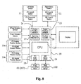
- FIG. 8 a block diagram of the electronically controlled bicycle transmission of the present invention is illustrated.
- the front and rear deraille 12 and 13 are operated by an electronic controller or control unit 20 that is electrically coupled to a pair of electronic shifters 21 and 22 via electric shift cables.
- the front and rear deraille 12 and 13 are operated by the rider depressing shift buttons to move a chain C between at least two front sprockets or chain wheels S 1 and S 2 or rear gears G 1 , G 2 , G 3 , G 4 , G 5 , G 6 or G 7 of the bicycle drive train.
- Each of the electronic shifters 21 and 22 is preferably provided with a pair of shift buttons that are operatively coupled to the electronic controller 20, preferably in accordance with U.S. Patent No.
- the electronic controller 20 preferably includes front and rear automatic shifting programs that are activated by depressing the mode switches on the electronic shifters 21 and 22.
- the electronic controller 20 is a processing mechanism that preferably includes a microcomputer 23 with shifting control programs that controls the front and rear deraille 12 and 13, as discussed below.
- the electronic controller 20 can also include other conventional components such as an input interface circuit, an output interface circuit, and storage devices such as a ROM (Read Only Memory) device and a RAM (Random Access Memory) device.
- the internal RAM of the electronic controller 20 stores statuses of operational flags and various control data.
- the internal ROM of the electronic controller 20 stores the predetermined parameter for various shifting operations.
- the electronic controller 20 also preferably includes an analog position memory 24 for storing a plurality of analog position values, a digital position memory 25 for storing a plurality of digital position values, a position counter 26; an updating mechanism 27 for updating at least one of the analog position memory 24 and the digital position memory 25, a front derailleur motor driver 28 for providing signals that moves the front derailleur 12, and a rear derailleur motor driver 29 for providing signals that moves the rear derailleur 13.
- the microcomputer 23 determines the proper signals for driving the front and rear derailleurs 12 and 13 using the signals received from front and rear derailleur positioning mechanisms 30a and 30b, respectively.
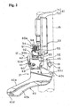
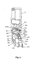
- the motorized front derailleur 12 basically includes a motorized front derailleur unit 31, a motorized front derailleur mounting member 32, a front derailleur motor unit 33 and a motor linkage 34.
- the motorized front derailleur unit 31, the front derailleur motor unit 33 and the motor linkage 34 are all mounted on the motorized front derailleur mounting member 32 that is configured and arranged to fixedly couple the motorized derailleur 12 to the seat tube 16 of the bicycle frame 14.
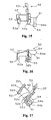
- the motorized front derailleur 12 is constructed to move between at least a low derailleur shift position as illustrated in Figures 1-4 and a top derailleur shift position as illustrated in Figure 5 .
- the motor linkage 34 is designed with a derailleur protection arrangement such that the derailleur motor unit 33 can operated even though the motorized front derailleur unit 32 becomes jammed.
- the basic operation of shifting the chain C is relatively conventional, and thus, will not be illustrated shown in detail herein.
- the front derailleur unit 31 basically includes a chain guide 40, a derailleur linkage 41 and a fixing body 42 that is part of the mounting member 32, as explained below.
- the derailleur linkage 41 together with the chain guide 40 and the fixing body 42 preferably form a four-bar linkage that controls the lateral movement of the chain guide 40.
- the derailleur linkage 41 is configured and arranged to operatively couple between the fixing body 42 and the chain guide 40 for lateral movement of the chain guide 40 between at least a top derailleur shift position and a low derailleur shift position, i.e., at least first and second derailleur shift positions.
- the chain guide 40 is movably coupled to the fixing body 42 by a derailleur linkage 41 that is operatively coupled to the motor linkage 34 to move the chain guide 40 between a first derailleur shift position and a second derailleur shift position in response to operation of front derailleur motor unit 33.
- This lateral movement of the chain guide 40 causes the chain C to be shift between the sprockets 22 and 23 of the bicycle drive train 24.
- the chain guide 40 is preferably constructed of a hard rigid material.
- the chain guide 40 is preferably constructed of a metal material such as a rigid sheet metal that is bent to the desired shape.
- the chain guide 40 has first and second shifted pivot points P 1 and P 2 , respectively, for pivotally securing the derailleur linkage 41 to the chain guide 40.
- pivot pins 43 and 44 pivotally couple the chain guide 40 to the derailleur linkage 41.
- the chain guide 40 has a chain receiving slot that is formed by a pair of vertical shift plates 40a and 40b. The vertical shift plates 40a and 40b are adapted to engage the chain C, and thus, move the chain C in a direction substantially transverse to the bicycle 10.
- the shift plates 40a and 40b are connected together by a pair of plates 40c and 40d.
- the upper plate 40c is integrally formed between the shift plates 40a and 40b.
- the lower plate 40d has one end that is integrally formed with the outer shift plate 40a, and the other end that is attached to the inner shift plate 40bvia a fastener, such as a screw or rivet.
- the derailleur linkage 41 basically includes a first or outer link 45 and a second or inner link 46 with first ends pivotally coupled to the fixing body 42 and with second ends pivotally coupled to the chain guide 40.
- the first link 45 has a first end 45a pivotally coupled to a first fixed pivot point P 3 of the fixing body 42 by a pivot pin 47 and a second end 45b pivotally coupled to the first shifted pivot point P 1 of the chain guide 40 by the pivot pin 43.
- the second link 46 has a first end 46a pivotally coupled to a second fixed pivot point P 4 of the fixing body 42 by a pivot pin 48 and a second end 46b pivotally coupled to the second shifted pivot point P 2 of the chain guide 40 by the pivot pin 44.
- the derailleur linkage 41 is preferably a four-bar linkage that is formed by the first or outer link 45, the second or inner link 46, the portion of the chain guide 40 extending between the first and second shifted pivot points P 1 and P 2 , and the portion of the fixing body 42 extending between the first and second pivot fixed points P 3 and P 4 .
- pivot axes of the pivot points P 1 , P 2 , P 3 and P 4 are all substantially parallel to each other.
- the chain guide 40 When the derailleur linkage 41 holds the chain guide 40 in its extended most position, the chain guide 40 is located over the outermost sprocket 22, i.e., the furthest sprocket from the seat tube 16. When the derailleur linkage 41 holds the chain guide 40 in its retracted most position, the chain guide 40 is located over the innermost sprocket 23, i.e., the closest sprocket to the seat tube 16.
- the first or outer link 45 includes two threaded holes 45c and 45d that receive a top position adjustment screw 49 and a low position adjustment screw 50.
- the two threaded holes 45c and 45d of the first or outer link 45 and the adjustment screws 49 and 50 form a mechanical adjustment device that finely adjusts the top and low positions of the chain guide 40.
- the mechanical adjustment device is configured and arranged to change the first and second derailleur shift positions (top and low end gear positions) of the chain guide 40 relative to the fixing body 42.
- the low adjustment screw 50 is configured and arranged to change the low derailleur shift position of the chain guide 40 relative to the fixing body 42
- the top adjustment screw 49 is configured and arranged to change the top derailleur shift position of the chain guide 40 relative to the fixing body 42.
- adjustment screws 49 and 50 are mounted on the first or outer link 45, it will be apparent from this disclosure that the adjustment screws 49 and 50 can be mounted on any one of the fixing body 42, the chain guide 40 and the links 45 and 46 with a free end of the adjustment screw contacting one of the fixing body 42, the chain guide 40 and the links 45 and 46 or the motor linkage 34 in which the adjustment screw is not threadedly coupled thereto. Also it will be apparent from this disclosure that an adjustment screw can be threadedly coupled to one of the motor linkage 34 and the derailleur linkage 41 with a free end of the adjustment screw contacting one of the motor linkage 34 and the derailleur linkage 41 in which the adjustment screw is not threadedly coupled thereto.
- the first or low adjustment screw 50 is configured and arranged to change the first or low derailleur shift position of the chain guide 40 relative to the fixing body 42 by the free end of the low adjustment screw 50 contacting the fixing body 42
- the second or top adjustment screw 49 is configured and arranged to change the second or top derailleur shift position of the chain guide 40 relative to the fixing body 42 by the free end of the top adjustment screw 49 contacting the motor linkage 34 as explained below.
- the motorized front derailleur mounting member 32 basically includes a bicycle frame mounting portion 51, a front derailleur mounting portion 52 and a motor unit mounting portion 53.
- the bicycle frame mounting portion 51, the front derailleur mounting portion 52 and the motor unit mounting portion 53 are integrally formed as a one-piece, unitary member.
- the front derailleur mounting portion 52 and the motor unit mounting portion 53 form a derailleur motor support structure.
- the bicycle frame mounting portion 51 is configured and arranged to be coupled to the seat tube 16 of the bicycle frame 14 by the bracket 18.
- the bicycle frame mounting portion 51 includes a projection 54 that projects outwardly from a first side of the motorized front derailleur mounting member 32 to a free end that forms a curved front surface 54a with a threaded hole 54b.
- the curved front surface 54a is configured and arranged to contact a corresponding curved portion of the bracket 18 such that the motorized front derailleur mounting member 32 cannot rotated relative to the bracket 18.
- One of the fasteners or bolts 19 is threaded into the threaded hole 54b of the bicycle frame mounting portion 51, while the other two fasteners or bolts 19 are threaded into the threaded holes formed the seat tube 16 such that the motorized front derailleur mounting member 32 is secured to the bicycle frame 14 via the bracket 18.
- the front derailleur mounting portion 52 is configured and arranged to be coupled to a derailleur linkage 41 of the front derailleur unit 31.
- the front derailleur mounting portion 52 has first and second link supporting parts 52a and 52b that are configured and arranged to define a link receiving space therebetween for receiving the first and second links 45 and 46.
- the first and second link supporting parts 52a and 52b are configured and arranged to form the front derailleur fixing body 42.
- the first and second link supporting parts 52a and 52b each include a first pivot pin mounting hole 52c forming the first pivot axis of the first fixed pivot point P 3 and a second pivot pin mounting hole 52d forming the second fixed pivot point P 4 .
- the first and second link supporting parts 52a and 52b are configured and arranged such that the first and second link supporting parts 52a and 52b are spaced different at the first pivot pin mounting holes 52c than at the second pivot pin mounting holes 52d to accommodate the different sizes of the first and second links 45 and 46.
- the second pivot axis of the second fixed pivot point P 4 is substantially parallel to the first pivot axis of the first fixed pivot point P 3 .
- the first pivot axis of the second pivot pin mounting holes 52d that defines the second fixed pivot point P 4 passes through the threaded hole 54b.
- the motor unit mounting portion 53 is configured and arranged to be coupled to the front derailleur motor unit 33.
- the motor unit mounting portion 53 includes a plurality (three) of threaded holes 53 a that form a plurality mounting parts of the motor unit mounting portion 53.
- the motor unit mounting portion 53 also includes an output shaft cutout 53b that has a center axis that is substantially parallel to the pivot axes of the first and second fixed pivot points P 3 and P 4 of the front derailleur mounting portion 52.
- the output shaft cutout 53b of the motor unit mounting portion 53 is a hole surrounded by material of the motor unit mounting portion 53.
- the motor unit mounting portion 53 further includes a pin mounting hole 53c in which a spring mounting pin 55 is mounted.
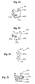
- the front derailleur motor unit 33 basically includes a derailleur motor unit support structure 61 ( Figures 2 , 35 and 38-42 ), a front derailleur motor 62 ( Figures 36 and 37 ), a motor drive train 63 ( Figures 36 and 37 ), and a position control mechanism or device 64 ( Figures 35-36 ).
- the front derailleur motor unit 33 is mounted to the motor unit mounting portion 53 that forms a derailleur motor support.
- the front derailleur motor unit 33 is operatively coupled the chain guide 40 by the motor linkage 34 and the derailleur linkage 41.
- operation of the front derailleur motor unit 33 by the controller 20 causes the chain guide 40 to be shifted between the low and top derailleur shift positions.
- the front derailleur motor 62 is electrically connected the controller 20 which has the microcomputer 23 and the front derailleur motor driver circuit 28.
- An overcurrent detecting circuit is operatively coupled to the central processing unit of the microcomputer 23 and/or the motor driver circuit 28 for stopping the front derailleur motor 62 as explained below.
- the power source or battery can be located in either the controller 20 or a separate housing (not shown), and is operatively coupled to the front derailleur motor 62 via the motor driver circuit 29 and to the overcurrent detecting circuit.
- the central processing unit of the microcomputer 23, the motor driver circuit 29 and the overcurrent detecting circuit operate together to stop the movement of the front derailleur motor 62 upon detection of the front derailleur motor 62 beginning to lockup.
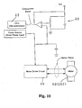
- the overcurrent detecting circuit has a comparator that compares the voltage being inputted into the motor driver circuit 29 with a predetermined reference voltage Vcc. If the voltage in the motor driver circuit 29 becomes greater than the predetermined voltage Vcc, then the comparator will send a signal to the central processing unit of the microcomputer 23 to send a motor control signal to the motor driver circuit 29 which will stop the flow of current to the front derailleur motor 62. In other words, when the front derailleur motor 62 begins to lockup, this will increase the voltage level such that an overcurrent signal is sent from the overcurrent detecting circuit back to the central processing unit of the microcomputer 23 to stop the electricity from energizing the front derailleur motor 62.
- the derailleur motor unit support structure 61 basically includes a motor unit casing or housing 71 ( Figures 38-42 ) and a motor unit cover 72 ( Figures 2-4 ).
- the casing 71 and the cover 72 are configured and arranged to enclose and support the front derailleur motor 62 and the motor drive train 63.
- the casing 71 and the cover 72 are constructed of a rigid, lightweight material such as a hard plastic material.
- the casing 71 includes a recess 71a for receiving and supporting the front derailleur motor unit 33 therein.
- the casing 71 also includes a pair of gear shaft supporting bores 71b and 71c and an output shaft hole 71d that are configured and arranged to support the motor drive train 63.
- the front derailleur motor 62 is mounted to the casing 71 of the derailleur motor unit support structure 61.
- the front derailleur motor 62 is a reversible electric motor that is powered by a battery source or a generator ( Figure 10 ).
- the front derailleur motor 62 is electrically coupled to the controller 20 by an electrical cord and to the power source (battery source or generator) by another electrical cord.
- the front derailleur motor 62 has a driving shaft 75 that is operatively coupled to the motor drive train 63. Reversible electric motors such as the front derailleur motor 62 are well known. Thus, the front derailleur motor 62 will not be discussed or illustrated in detail.
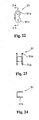
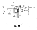
- the motor drive train 63 basically includes a worm gear 81, a first intermediate gear 82, a second intermediate gear 83, and an output gear 84.
- the output gear 84 is mounted on an output shaft 85.
- the motor drive train 63 transmits rotational movement of the driving shaft 75 of the front derailleur motor 62 to the motor linkage 34 via the output shaft 85.
- the worm gear 81 is mounted on the driving shaft 75 of the front derailleur motor 62, with the spiral tooth of the worm gear 81 engaged with a first set of teeth of the first intermediate gear 82.
- the first intermediate gear 82 has a second set of teeth that engages a first set of teeth of the second intermediate gear 83, which in turn has a second set of teeth that engages the teeth of the output gear 84.
- the output gear 84 is mounted on the output shaft 85, which in turn is coupled to the motor linkage 34.
- the motor drive train 63 is disposes between the driving shaft 75 of the front derailleur motor 62 and the output shaft 85.
- the output shaft 85 is rotatably supported in the output shaft hole 71d of the casing 71 by a bearing 86.
- the bearing 86 can be mounted on the motorized derailleur mounting member 32 instead of the casing 71 such that the output shaft 85 is rotatably supported on the motorized derailleur mounting member 32.
- the output shaft 85 is configured and arranged to rotate about a rotational axis A 1 between a first rotational position and a second rotational position that is opposite the first rotational direction by rotation of the driving shaft 75 of the front derailleur motor 62.
- the output shaft 85 includes an eccentric drive pin 85a having an axis A 2 that is offset from a rotational axis A 1 of the output shaft 85.
- the position control mechanism 64 basically includes a printed circuit board 87 with a digital signal providing mechanism in the form of a digital position sensor 89 and an analog signal providing mechanism in the form of an analog (top-low brush) position sensor 90.
- the digital position sensor 89 forms a digital position sensing device
- the analog position sensor 90 forms a mechanical/electrical position sensing device.
- the printed circuit board 87 has a plurality of electrical circuits formed thereon in a conventional manner for controlling the operation of the front derailleur motor 62 via the controller 20 in response to signals from the electronic shifters 21 and 22, the digital position sensor 89 and the analog position sensor 90 as well as other sensors as such a wheel rotation sensor and a crank rotation sensor ( Figure 8 ).
- the digital position sensor 89 and the analog position sensor 90 are configured and arranged to send digital and analog signals, respectively, to the controller 20 such that the controller 20 controls the electrical current to the front derailleur motor 62.
- the digital position sensor 89 is formed by a position sensor element or shutter wheel 89a and a photo interrupter 89b.
- the angular position of the output shaft 85 is determined by utilizing the shutter wheel 89a and the photo interpreter 89b.
- the shutter wheel 89a is mounted on the first intermediate gear 82 such that the shutter wheel 89a rotates therewith.
- the shutter wheel 89a is provided with a plurality of circumstantially spaced apart openings that are detected by the photo interpreter 89.
- the photo interpreter 89b senses the openings in the shutter wheel 89a to determine the relative position of the first intermediate gear 82. Since the position of the first intermediate gear 82 directly relates to the position of the output shaft 85, the position of the output shaft 85 can easily be determined.
- the controller 20 can determine the position of the chain guide 40 based on the relative position of the first intermediate gear 82.
- the a photo interrupter 89b is preferably a dual channel photo interrupter having a light source or LED disposed on one side of the shutter wheel 89a and a light detector such as a phototransistor disposed on the other side of the shutter wheel 89a.
- Rotation of the shutter wheel 89a by the front derailleur motor 62 causes the passage of light of LED to phototransistor to be intermittently blocked, thus producing a digital signal having a period determined by the rate of rotation of the shutter wheel 89a.
- the shape of the digital signal typically will have square or rectangular saw tooth configuration with each of the pulses representing one of a plurality of angular positions of the output shaft 85.
- the digital position sensor 89 functions as an intermittent optical sensor that can detect both the rotational direction and the angular position of the output shaft 85 of the motor drive train 63 of the motor 62.
- the digital position sensor 89 sends a position signal indicative of an angular position and rotational direction of the output shaft 85 of the motor drive train 63 of the motor 62.
- the analog position sensor 90 which operates like a potentiometer in a known manner, merely acts as an on-off sensor to indicate an edge of the top contact range spaced from the top stop position and an edge of the low contact range spaced from the low stop position.
- the analog position sensor 90 includes an electrical contact plate with three stationary electrical brushes 90a, 90b and 90c that are mounted on the printed circuit board 87, and three movable electrical contacts 90a', 90b' and 90c' that are mounted on the output shaft 85 to rotate therewith.
- the electrical brushes 90a, 90b and 90c are coupled in a cantilever fashion to the printed circuit board 87 with their free ends arranged to selectively contact the movable electrical contacts 90a', 90b' and 90c' that are mounted to the output gear 84 of the output shaft 85.
- electrical contacts 90a', 90b' and 90c' rotate together with the output gear 84 and the output shaft 85.
- the brushes 90a', 90b' and 90c' cooperate with the contacts 90a, 90b and 90c to complete electrical circuit.
- the electrical brush 90a and the top position contact 90a' selectively contact each other to define a top derailleur position or top end gear range of the output shaft 85 from the top stop or top lockup position.
- the electrical brush 90b and the low position contact 90b' selectively contact each other to define a low derailleur position or low end gear range of the output shaft 85 from the low stop or low lockup position.
- the electrical brush 90c and the ground contact 90c' contact each other to from a ground connection either while the electrical brush 90a and the top position contact 90a' are contacting or while the electrical brush 90b and the low position contact 90b' are contacting.
- an analog or mechanical signal is sent to the controller 20.
- the analog or mechanical signal is stop.
- the controller 20 can determine when the output shaft 85 is located at the top derailleur position or top end gear range.
- the controller 20 can determine when the output shaft 85 is located at the low derailleur position or low end gear range.
- the top derailleur position of the chain guide 40 is controlled by the top adjustment screw 49 contacting the motor linkage 34, while the low derailleur position of the chain guide 40 is controlled by the low adjustment screw 50 contacting the motor linkage 34.
- the analog position sensor 90 merely acts as an on-off sensor to indicate when the electrical brushes 90a and 90b engage or disengage the top and low position contacts 90a' and 90b', respectively. More specifically, the controller 20 determines the precise location of the edges of the top and low position contacts 90a' and 90b' that are spaced from the top and low stop positions, respectively.
- the controller 20 is operatively coupled to the front derailleur motor 62 and the position control mechanism 64.
- the controller 20 is configured to detect a predetermined lockup position of the front derailleur motor 62 occurring at one of the first and second derailleur shift positions.
- the controller 20 is further configured to set a predetermined stop position for the front derailleur motor 62 that is calculated distance prior to the lockup position based on the position signal of the position control mechanism 64.
- the front derailleur motor 62 should be calibrated to avoid an overcurrent from occurring when the output shaft 85 is driven to a lockup position.
- this calibration could be conducted at the factory or before mounting to the bicycle 10.
- the controller 20 is set to a calibration mode to start the process set forth in the flow chart of Figure 9 .
- the front derailleur motor 62 is first energized by the controller 20 (e.g., depressing one of the shift buttons of the shifter 21 or otherwise supply electrical current to motor 62) to provide electrical current to the front derailleur motor 62. If the top position of the derailleur motor 62 is to be calibrated, the front derailleur motor 62 is driven from the low position towards the top position until the front derailleur motor 62 locks up.
- the output gear 84 has teeth that do not extend completely around periphery of the output gear 84.
- the top and low lockup positions of the derailleur motor 62 occurs when the teeth of the second intermediate gear 83 reach the ends of the teeth of the output gear 84.
- the front derailleur motor 62 locks up and an overcurrent is produced.
- step S2 the program of the controller 20 determines when the overcurrent occurs.
- the overcurrent circuit ( Figure 10 ) detects a rise in the voltage by comparing the currently detected voltage to a reference voltage Vcc. Accordingly, in step S3, the controller 20 stops electrical current to the front derailleur motor 62.
- the stop or lockup position is stored in the memory of the controller 20 in step S4.
- the relative position of the position sensor element or shutter wheel 89a is stored in the digital position memory 25 of the controller 20.
- step S5 the controller 20 drives the front derailleur motor 62 to the low position, preferably by this is done automatically in the calibration mode.
- the controller 20 detects and stores the edge of the top position contact 90' in step S6.
- the photo sensor element 89a is rotated such that the photo interrupter 86 counts the openings in the position sensor element 89a as pulses that are used to calculate and store the number of pulses between the edge of the top position contact and the lockup position at the top derailleur shift position.
- step S8 the controller 20 calculates a new stop position that is a calculated distance prior to the lockup position. For example, if there are ten pulses between the edge of the top position contact and the lockup position, then the new stop position can be set to seven pulses from the lockup position. Accordingly, when the front derailleur motor 62 is energized by the rider shifting from a low position to the top position, the controller 20 will deenergize the front derailleur motor 62 such that motor will stop seven pulses counts from the lockup position. In this way, the front derailleur motor 62 will not be driven to a lockup condition in future up shifts from the top position. It will be apparent to those skilled in the art from this disclosure that the low position can also be calibrated in a similar matter.
- step S5 can be eliminated by performing detecting of the top position edge (step S6) and the counting of the pulse (step S8) in a different order.
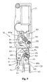
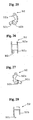
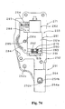
- the motor linkage 34 basically includes a drive or motor link 91, a saver link 92, a saver link biasing element 93 and a position biasing element 94.
- the saver link 92 and the saver link biasing element 93 form a jamming protection arrangement.
- the motor linkage 34 is operatively coupled between the eccentric drive pin 85a of the output shaft 85 and the derailleur linkage 41. This jamming protection arrangement is configured and arranged to move between a force transmitting state and a force override state.
- the drive link 91 is configured and arranged relative to the output shaft 85 and the derailleur linkage 41 to shift the chain guide 40 between the first derailleur shift position and a second derailleur shift position.
- the drive link 91 as particularly seen in Figures 23-25 , has a first drive link end 91a and a second drive link end 91b.
- the first drive link end 91a is mounted on the eccentric drive pin 85a of the output shaft 85 such that the eccentric drive pin 85a can rotate within the holes formed in the first drive link end 91a.
- the second drive link end 91b is pivotally coupled to the saver link 92 by a pivot pin 95.
- the saver link 92 preferably has a first saver link end 92a, a second saver link end 92b and a control or stop flange 92c.
- the first saver link end 91a of the saver link 92 is pivotally coupled to the second drive link end 91b of the drive link 91 by the pivot pin 95.
- the second saver link end 92b is operatively coupled to the first or outer link 45 of the derailleur linkage 41.
- the control or stop flange 92c extends from the second saver link end 92b and is arranged to contact the top adjustment screw 49 when the motor linkage 34 is driven to the top derailleur shift position as seen in Figure 6 .
- the second or top adjustment screw 49 is configured and arranged to change the second or top derailleur shift position of the chain guide 40 relative to the fixing body 42 by the free end of the top adjustment screw 49 contacting the control or stop flange 92c of the saver link 92.
- the front derailleur unit 31 is mounted to the frame 12 by the motorized front derailleur mounting member 32 and bracket 18. Then the top derailleur shift position is set by adjusting the top adjustment screw 49 so that the chain guide 40 is disposed over the front chain wheel 22.
- This adjustment of the top derailleur shift position causes the relative orientation between the outer link 46 and the saver link 92 to change.
- the adjusting of the top adjustment screw 49 changes the relative orientation between the outer link 46 and the saver link 92 by counteracting the urging force of the saver link biasing element 93, i.e., compressing the saver link biasing element 93.
- the low derailleur shift position is also changed by the adjusting of the top adjustment screw 49 because the chain guide 40 moves with the outer link 46.
- the low position is next set by using the low adjustment screw 50, which contacts the fixing body 42, such that the chain guide 40 is disposed over the smaller front chain wheel 23.
- the adjusting of the low adjustment screw 50 changes the relative orientation between the outer link 46 and the saver link 92 when the chain guide 40 is disposed over the front chain wheel 23 by further counteracting the urging force of the saver link biasing element 93, i.e., further compressing the saver link biasing element 93.
- the saver link biasing element 93 is preferably a torsion spring having a coiled portion 93a, a first leg portion 93b and a second leg portion 93c.
- the coiled portion 93a is located about the pivot pin 47 that connects the saver link 92 to the first or outer link 45.
- the first leg portion 93b of the saver link biasing element 93 engages the saver link 92, while the second leg portion 93b contacts the first or outer link 45 of the derailleur linkage 41.
- the saver link 92 is biased in a counter clockwise direction about pivot pin 47 as viewed from the rear of the derailleur.
- the first or outer link 45 is also biased in a counterclockwise direction about the pivot pin 47 as viewed from the rear of the derailleur.
- the saver link biasing element 93 is configured and arranged to apply an urge force that normally maintains a substantially rigid connection between the drive link 91 and the derailleur linkage 41.
- the saver link 92 is pivotally coupled to the derailleur linkage 41 and the saver link biasing element 93 is operatively coupled between the saver link 92 and the derailleur linkage 41 to urge the saver link 92 from the force override state to the force transmitting state such that a substantially rigid connection is normally maintained between the saver link and the derailleur linkage 41.
- the saver link 92 and the saver link biasing element 93 form a non-rigid connection that connects a second drive link end 91b of the drive link 91 to the derailleur linkage 41.
- This non-rigid connection forms the jamming protection arrangement.
- the position biasing element 94 is preferably a tension spring that has a first end coupled to the eccentric drive pin 85a and a second end connected to the spring mounting pin 55 of the motor unit mounting portion 53.
- the position biasing element 94 is configured and arranged such that the urging force of the position biasing element 94 holds the motor linkage 34 in either the top position or the low position. In other words, when the motor linkage 34 is in the top position, the line of force of the position biasing element 94 is offset from the rotational axis A 1 of the output shaft 85 to apply a clockwise force on the output shaft 85 as viewed from the rear of the derailleur 12.
- the position biasing element 94 is configured and arranged to assure assist in the holding chain guide 40 in either the top or low position when the motor is no longer energized.
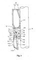
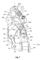
- the rear derailleur 13 is mounted to the frame 14 in close proximity to the sprocket unit for moving chain C among the plurality of rear sprockets G 1 -G 7 .
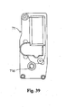
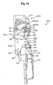
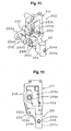
- the rear derailleur 13 includes a rear derailleur control housing 131 that is mounted between a base member 132 and an outer cover 133.
- the base member 132 is swingably mounted to the frame 14 in a known manner, and it includes an electrical connector for connecting to a complementary connector on intermediate communication path that is connected to the controller 20.
- the outer cover 133 and the rear derailleur control housing 131 are mounted to the base member 132 by screws 134 and 135.
- the screws 134 extend through openings in the outer cover 133, through the spacer tubes 137 that extend through openings 138 in a rear derailleur control housing cover 140 and into threaded openings 142 in the base member 132.
- the screws 135 extend through openings 144 in the outer cover 133, and into threaded openings 148 in the base member 132.
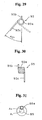
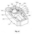
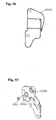
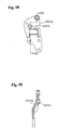
- the rear derailleur 13 further comprises link members 150 and 152 pivotally coupled to the rear derailleur control housing 131 through respective pivot shafts 154 and 156, wherein the link member 152 is non-rotatably fixed to the pivot shaft 156 by a flat 156a ( Figure 47 ).
- the other ends of link members 150 and 152 are pivotally coupled to a movable member 158 through respective the pivot shafts 160 and 162.
- the movable member 158 rotatably supports a chain guide 164 which, in turn, rotatably supports a guide pulley 166 and a tension pulley 168 for engaging the chain C in a known manner.
- a rear derailleur motor 180 ( Figures 45-47 ) rotates the pivot shaft 156 for causing the link member 152 to move the movable member 158 and the chain guide 164 laterally for transferring chain C among the plurality of rear sprockets G1-G7.
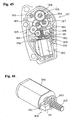
- Figure 45 is a view illustrating the contents of the rear derailleur control housing 131 with the rear derailleur control housing cover 140 as well as a contact plate 182 removed, as discussed below.
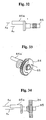
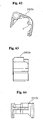
- the rear derailleur motor 180 includes a pinion drive shaft 183 that drives pivot shaft 156 through a gear reduction mechanism comprising gears 184, 185, 186, 187 and 188, wherein a small diameter gear portion of each gear 184, 185, 186 and 187 drives a larger diameter gear portion of the next gear in the power transmission path.
- the gear 188 rotates integrally with the pivot shaft 156.
- a digital signal providing mechanism in the form of a digital position sensor 189 is mounted in the rear derailleur control housing 131.
- the digital position sensor 189 includes a position sensor element or shutter wheel 190 that rotates integrally with the pinion drive shaft 183, a light source or LED 191 disposed on one side of the shutter wheel 190, and a light detector such as a phototransistor 192 disposed on the other side of the shutter wheel 190.
- Rotation of the shutter wheel 190 with the pinion drive shaft 183 causes the passage of light of LED 191 to phototransistor 192 to be intermittently blocked, thus producing a digital signal having a period determined by the rate of rotation of the shutter wheel 190.
- the shape of the digital signal typically will have square or rectangular saw tooth configuration depending upon the operation condition.
- digital position sensor 189 functions as an intermittent optical sensor in this embodiment.
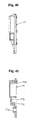
- an analog signal providing mechanism in the form of an analog position sensor 193 also is mounted in rear derailleur control housing 131.
- Analog position sensor 193 comprises a contact plate 182 and a brush plate 194.
- the contact plate 182 is mounted to the rear derailleur control housing 131 by screws 195 that screw into threaded openings 196 ( Figure 45 ), and it includes resistive contacts 197a and 197b.
- the brush plate 194 rotates integrally with pivot shaft 156, and it includes brushes 198a and 198b for contacting resistive contacts 197a and 197b to operate like a potentiometer in a known manner.
- the calibration and shifting movements of the motorized rear derailleur 13 are controlled by the controller 20 of the first embodiment.
- the flow chart of Figure 9 and the schematic block of the overcurrent in Figure 10 are used to control the motorized rear derailleur 13 during the initial calibration of the motorized rear derailleur 13 by the controller 20.
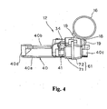
- the motorized front derailleur 212 is identical to the motorized front derailleur 12, as discussed above, except that the motorized front derailleur mounting member 32 and the front derailleur motor mounting unit 33 of the first embodiment have been replaced with a modified motorized front derailleur mounting member 232 and a modified front derailleur motor unit 233.
- all other parts of the front motorized derailleur 212 are identical to the motorized front derailleur 12 of the first embodiment, except for the modified motorized front derailleur mounting member 232 and the modified front derailleur motor unit 233.
- the parts of the second embodiment that are identical to the parts of the first embodiment will be given the same reference numerals as the parts of the first embodiment. Moreover, the descriptions of the parts of the second embodiment that are identical to the parts of the first embodiment may be omitted for the sake of brevity.
- the motorized front derailleur 212 of the second embodiment replaces the motorized front derailleur 12 as seen in Figure 8 .
- the calibration and shifting movements of the motorized front derailleur 212 are controlled by the controller 20 of the first embodiment.
- the flow chart of Figure 9 and the schematic block of the overcurrent in Figure 10 are used to control the motorized front derailleur 212 during the initial calibration of the motorized front derailleur 212 by the controller 20.
- the motorized front derailleur mounting member 232 basically includes a bicycle frame mounting portion 251, a front derailleur mounting portion 252 and a motor unit mounting portion 253 that includes an integrated front derailleur motor casing 271.
- the bicycle frame mounting portion 251, the front derailleur mounting portion 252 and the motor unit mounting portion 253 are integrally formed as a one-piece, unitary member together with the front derailleur motor casing 271.
- the front derailleur mounting portion 252 and the motor unit mounting portion 253 form a derailleur motor support structure.
- the bicycle frame mounting portion 251 is configured and arranged to be coupled to the seat tube 16 of the bicycle frame 14 by the bracket 18 in the same manner as the first embodiment.
- the bicycle frame mounting portion 251 includes a projection 254 that projects outwardly from a first side of the motorized front derailleur mounting member 232 to a free end that forms a curved front surface 254a with a threaded hole 254b.
- the curved front surface 254a is configured and arranged to contact a corresponding curved portion of the bracket 18 such that the motorized front derailleur mounting member 232 cannot rotated relative to the bracket 18.
- the front derailleur mounting portion 252 is configured and arranged to be coupled to the derailleur linkage 41 of the front derailleur unit 31 in the same manner as the first embodiment, as discussed above.
- the front derailleur mounting portion 252 has first and second link supporting parts 252a and 252b that are configured and arranged to define a link receiving space therebetween for receiving the first and second links 45 and 46.
- the first and second link supporting parts 252a and 252b are configured and arranged to form the front derailleur fixing body 242.
- the first and second link supporting parts 252a and 252b each include a first pivot pin mounting hole 252c forming the first pivot axis of the first fixed pivot point P 3 and a second pivot pin mounting hole 252d forming the second fixed pivot point P 4 .
- the first and second link supporting parts 252a and 252b are configured and arranged such that the first and second link supporting parts 252a and 252b are spaced different at the first pivot pin mounting holes 252c than at the second pivot pin mounting holes 252d to accommodate the different sizes of the first and second links 45 and 46.
- the first pivot axis of the second pivot pin mounting holes 252d passes through the threaded hole 254b as best seen in Figure 53 .
- the motor unit mounting portion 253 is configured and arranged to be coupled to the front derailleur motor unit 233.
- the motor unit mounting portion 253 has cup shaped portion that forms the front derailleur motor casing 271.
- the motor unit mounting portion 253 has an output shaft opening 253b that has a center axis that is substantially parallel to the pivot axes of the first and second fixed pivot points of the front derailleur mounting portion 252.
- the motor unit mounting portion 253 further includes various mounting holes for securing the parts of the front derailleur motor unit 233 thereto.
- the front derailleur motor unit 233 is designed to be mounted to the casing 271 of the motorized front derailleur mounting member 232.
- the front derailleur motor unit 233 basically includes a motor unit cover structure 260, a derailleur motor support structure 261, a derailleur motor 262, a motor drive train 263 and a position control mechanism or device 264.
- the front derailleur motor unit 233 is operatively coupled to the chain guide 40 by the motor linkage 34 and the derailleur linkage 41 in the same manner as the first embodiment.
- operation of the front derailleur motor unit 233 by the controller 20 causes the chain guide 40 to be shifted between below and top shift positions.
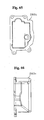
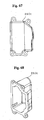
- the motor unit cover structure 260 of the front derailleur motor unit 233 basically includes a rear cover 260a ( Figures 56-59 ), an intermediate cover 260b ( Figures 60-64 ), and a front cover 260c ( Figures 65-68 ).
- the parts of the motor unit cover structure 260 are constructed of rigid materials such as a hard rigid plastic or a metal.
- the rear cover 260a, the intermediate cover 260b, and the front cover 260c are fixedly coupled to the casing 271 by fasteners (not shown).
- the rear cover 260a is preferably made of metal, and has an output shaft receiving bore 260c that receives a bearing 265.
- the precise structures of the rear cover 260a, the intermediate cover 260b, and the front cover 260c are not important to the present invention, and thus, they will not be discussed in detail herein.
- the derailleur motor unit support 261 is configured and arranged to enclose and support the derailleur motor 262 and the motor drive train 263.
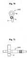
- the derailleur motor unit support 261 in the illustrated embodiment includes a main support 261a ( Figures 74 and 76 ) and a bottom gear support 261b ( Figures 77-79 ).
- the main support 261a and the bottom gear support 261b of the derailleur motor unit support 261 are constructed of rigid, light weight materials such as a hard plastic.
- the main support 261a is configured and arranged to support the derailleur motor 262, the motor drive train 263 and the position control mechanism 264.
- the derailleur motor 262 has a drive shaft 275 that is operatively coupled to the motor drive train 263.
- the derailleur motor 262 is a reversible electrical motor that is powered by a battery source or a generator.
- the derailleur motor 262 is electrically coupled to the controller 20 by an electrical cord and to a power source (battery source or a generator) by another electrical cord.
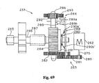
- the motor drive train 263 basically includes a driving gear 280, a first intermediate gear 281, a second intermediate gear 282, a worm gear 283 and an output gear 284.
- the output gear 284 is mounted on an output shaft 285.
- the motor drive train 283 transmits rotational movement of the driving shaft 275 of the derailleur motor 262 to the motor linkage 34 by the output shaft 285.
- the gears 280-284 are all constructed of a metal material.
- the driving gear 280 is mounted on the driving shaft 275 of the derailleur motor 262, with the teeth of the driving gear engaged with a first set of teeth of the first intermediate gear 281.
- the first intermediate gear 281 has a second set of teeth that engage a first set of teeth of the second intermediate gear 282.
- the second intermediate gear 282 and the worm gear 283 are mounted on an intermediate driven shaft 286.
- rotation of the second intermediate 282 causes the worm gear 283 to rotate therewith.
- the worm gear 283 has a spiral tooth that is engaged with the output gear 284 to rotate the output shaft 285.
- the output shaft 285 is rotatably supported at a rear end in the output shaft receiving bore 260c of the rear cover 260a by the bearing 265, at a center portion in the output shaft hole 271d of the casing 271 by a bearing 187 and at a forward end in a hole 261c of the main support 261a. Similar to the first embodiment, the output shaft 285 is configured and arranged to rotate about a rotational axis A 1 between a first rotational position and a second rotational position that is opposite the first rotational direction by rotation of the driving shaft 275 of the derailleur motor 262.
- the output shaft 285 is coupled to the motor or drive link 91 by an eccentric drive pin 285a having an axis A 2 that is offset from the rotational axis A 1 of the output shaft 285.
- the eccentric drive pin 285a is a separate part of the output shaft 285.
- the driving gear 292 is mounted on the intermediate driven shaft 286, which has the second intermediate gear 282 and the worm gear 283 mounted thereto.
- the driving gear 292 has its teeth engaged with the teeth of the position sensor gear 293 such that the driving gear 292 rotates the position sensor gear 293.
- the position sensor element 289 is mounted on the position sensor gear 293 such that they rotate together.
- the output shaft has an abutment X that contacts an abutment on the intermediate cover 260b as seen in Figure 51 .
- the motor 262 is in its top end position in which an overcurrent occurs.
- the derailleur 212 is calibrated such that a new stop position is set to avoid contact between the abutments X and Y using the position control mechanism 264.
- the position control mechanism 264 basically includes a printed circuit board 288, a digital signal providing mechanism in the form of a digital position sensor 289 and an analog signal providing mechanism in the form of an analog (top-low brush) position sensor 290.
- the digital position sensor 289 forms a digital position sensing device
- the analog position sensor 290 forms a mechanical/electrical position sensing device.
- the printed circuit board 288 has a plurality of electrical circuits formed thereon in a conventional manner for controlling the operation of the front derailleur motor 262 via the controller 20 in response to signals from the electronic shifters 21 and 22, the digital position sensor 289 and the analog position sensor 290 as well as other sensors as such a wheel rotation sensor and a crank rotation sensor ( Figure 8 ).
- the digital position sensor 289 and the analog position sensor 290 are configured and arranged to send digital and analog signals, respectively, to the controller 20 such that the controller 20 controls the electrical current to the front derailleur motor 262.
- the digital position sensor 289 is formed by a position sensor element or shutter wheel 289a and a photo interrupter 289b.
- the angular position of the output shaft 285 is determined by utilizing the shutter wheel 289a and the photo interpreter 289.
- the shutter wheel 289a is mounted on the position sensor gear 293 such that the shutter wheel 289a rotates therewith.
- the shutter wheel 289a is provided with a plurality of circumstantially spaced apart openings that are detected by the photo interpreter 289.
- the photo interpreter 289 senses the openings in the shutter wheel 289a to determine the relative position of the gear 293. Since the position of the gear 293 directly relates to the position of the output shaft 285, the position of the output shaft 285 can easily be determined.
- the controller 20 can determine the position of the chain guide 40 based on the relative position of the gear 293.
- the photo interrupter 289b is preferably a dual channel photo interrupter having a light source or LED disposed on one side of the shutter wheel 289a and a light detector such as a phototransistor disposed on the other side of the shutter wheel 289a.
- Rotation of the shutter wheel 289a by the front derailleur motor 262 causes the passage of light of LED to phototransistor to be intermittently blocked, thus producing a digital signal having a period determined by the rate of rotation of the shutter wheel 289a.
- the shape of the digital signal typically will have square or rectangular saw tooth configuration with each of the pulses representing one of a plurality of angular positions of the output shaft 285.
- the digital position sensor 289 functions as an intermittent optical sensor that can detect both the rotational direction and the angular position of the output shaft 285 of the motor drive train 263 of the motor 262.
- the digital position sensor 289 sends a position signal indicative of an angular position and rotational direction of the output shaft 285 of the motor drive train 263 of the motor 262.
- the analog position sensor 290 which operates like a potentiometer in a known manner, merely acts as an on-off sensor to indicate an edge of the top contact range spaced from the top stop position and an edge of the low contact range spaced from the low stop position.
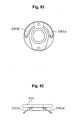
- the analog position sensor 290 includes an electrical contact plate with three stationary electrical contacts 290a, 290b and 290c that are formed on the printed circuit board 288, and two movable electrical brushes 290a' and 290b' that are mounted on the output shaft 285 to rotate therewith via a mounting member 291.
- the electrical brushes 290a' and 290b' are coupled in a cantilever fashion to the mounting member 291 with their free ends arranged to selectively contact the electrical contacts 290a, 290b and 290c that are mounted to the printed circuit board 288.
- electrical brushes 290a' and 290b' rotate together with the output shaft 285.
- the brushes 290a' and 290b' cooperate with the contacts 290a, 290b and 290c to complete an electrical circuit.
- the electrical brush 290a' selectively contacts both the contacts 290a and 290b to define the top and low derailleur positions (top and low end gear ranges) of the output shaft 285 from the stops or lockup positions.
- the electrical brush 290b' contact the ground contact 290c to form a ground connection either while the electrical brush 290a' is contacting either the contact 290a or 290b.
- an analog or mechanical signal indicating a top position is sent to the controller 20.
- the controller 20 can determine when the output shaft 285 is located at the top derailleur position or top end gear range.
- an analog or mechanical signal is sent indicating a low position to the controller 20.
- the controller 20 can determine when the output shaft 285 is located at the low derailleur position or low end gear range.
- the top derailleur position of the chain guide 40 is controlled by the top adjustment screw 49 contacting the motor linkage 34, while the low derailleur position of the chain guide 40 is controlled by the low adjustment screw 50 contacting the motor linkage 34.
- the analog position sensor 290 merely acts as an on-off sensor to indicate when the electrical brushes 290a' engage or disengage the top and low position contacts 290a and 290b, respectively. More specifically, the controller 20 determines the precise location of the edges of the top and low position contacts 290a and 290b that are spaced from the top and low stop positions, respectively.
- the controller 20 is operatively coupled to the front derailleur motor 262 and the position control mechanism 264 to run the program shown by the flow chart in Figure 9 .
- the controller 20 is configured to detect a predetermined lockup position of the front derailleur motor 262 occurring at the top derailleur shift positions when the abutments X and Y contact each other as seen in Figure 51 . This lockup position is defected by the overcurrent circuit of Figure 10 in the same manner as the first embodiment.
- the controller 20 is further configured to set a predetermined stop position for the front derailleur motor 262 that is calculated distance prior to the lockup position based on the position signal of the position control mechanism 264 in the same manner as the first embodiment.
Landscapes
- Engineering & Computer Science (AREA)
- Chemical & Material Sciences (AREA)
- Combustion & Propulsion (AREA)
- Transportation (AREA)
- Mechanical Engineering (AREA)
- Devices For Conveying Motion By Means Of Endless Flexible Members (AREA)
- Connection Of Motors, Electrical Generators, Mechanical Devices, And The Like (AREA)
- Electric Propulsion And Braking For Vehicles (AREA)
Claims (18)
- Transmission de bicyclette à commande électrique, comprenant :un dérailleur (12, 13, 212, 213) comprenant une unité de moteur de dérailleur électrique (33, 233) comprenant :un moteur de dérailleur (62, 262), et un arbre de sortie (85, 285) couplé fonctionnellement au moteur de dérailleur (62, 262) pour tourner dans une plage mobile comprenant une première position de vitesse de dérailleur et une deuxième position de vitesse de dérailleur ; etun contrôleur (20, 220) couplé fonctionnellement au moteur de dérailleur (62, 262), le contrôleur (20, 220) étant configuré pour détecter une position de verrouillage prédéterminée du moteur de dérailleur (62, 262) se produisant à l'une des première et deuxième positions de vitesse de dérailleur, et le contrôleur (20, 220) étant en outre configuré pour déterminer une position d'arrêt prédéterminée pour le moteur de dérailleur (62, 262) qui est située à une distance calculée avant la position de verrouillage,dans laquelle l'unité de moteur de dérailleur (33, 233) comprend un mécanisme de commande de position (64, 264) configuré et agencé pour fournir un signal de position indicatif d'une position angulaire de l'arbre de sortie (85, 285), dans laquelle le contrôleur (20, 220) est couplé fonctionnellement au mécanisme de commande de position (64, 264) pour calculer la distance de la position d'arrêt prédéterminée sur la base du signal de position du mécanisme de commande de position (64, 264) ; et
caractérisée en ce que le mécanisme de commande de position (64, 264) comprend un premier dispositif de détection de position (89, 289) configuré pour fournir une pluralité de valeurs de position angulaire correspondant à une pluralité de positions angulaires de l'arbre de sortie (85, 285). - Transmission de bicyclette à commande électrique selon la revendication 1, dans laquelle le premier dispositif de détection de position (89, 289) comprend un élément formant capteur de position (89a, 289a) qui est configuré pour se déplacer alors que l'arbre de sortie (85, 285) tourne et un photointerrupteur (89b, 289b) qui est configuré pour détecter la rotation de l'élément formant capteur de position (89a, 289a).
- Transmission de bicyclette à commande électrique selon la revendication 2, comprenant en outre une transmission de moteur (63, 263) couplée entre un arbre d'entraînement (75, 275) du moteur de dérailleur (62, 262) et l'arbre de sortie (85, 285), l'élément formant capteur de position (89a, 289a) étant couplé fonctionnellement à l'un de la transmission de moteur (63, 263), de l'arbre d'entraînement (75, 275) et de l'arbre de sortie (85, 285).
- Transmission de bicyclette à commande électrique selon la revendication 2 ou 3, dans laquelle le moteur de dérailleur (62, 262) est un moteur de dérailleur réversible qui est configuré et agencé pour faire tourner l'arbre de sortie (85, 285) dans un premier sens de rotation et un deuxième sens de rotation qui est opposé au premier sens de rotation, et le photointerrupteur (89b, 289b) comprend un premier canal agencé pour produire un premier signal et un deuxième canal agencé pour produire un deuxième signal qui est différent du premier signal pour indiquer le sens de rotation du moteur de dérailleur (62, 262).
- Transmission de bicyclette à commande électrique selon la revendication 1, dans laquelle le mécanisme de commande de position (64, 264) comprend un deuxième dispositif de détection de position analogue (90, 290) configuré pour fournir un signal de position angulaire correspondant à la première position de vitesse de dérailleur.
- Transmission de bicyclette à commande électrique selon la revendication 5, dans laquelle le dispositif de détection de position analogue (90, 290) comprend un potentiomètre comportant un élément formant capteur électrique avec un premier contact électrique (90a', 290a') qui est configuré pour se déplacer alors que l'arbre de sortie (85, 285) tourne et un premier balai électrique (90a, 290a) qui est configuré pour venir en contact avec le premier contact électrique (90a', 290a') pendant un déplacement dans une première plage finale de pignon qui correspond à l'une des première et deuxième positions de vitesse de dérailleur.
- Transmission de bicyclette à commande électrique selon la revendication 6, dans laquelle le potentiomètre comprend en outre un deuxième contact électrique (90b', 290b') disposé sur l'élément formant capteur électrique qui se déplace alors que l'arbre de sortie (85, 285) tourne et un deuxième balai électrique (90b, 290b) qui est configuré pour venir en contact avec le deuxième contact électrique (90b', 290b') pendant un déplacement dans une deuxième plage finale de pignon qui correspond à l'autre des première et deuxième positions de vitesse de dérailleur.
- Transmission de bicyclette à commande électrique selon l'une quelconque des revendications 1, 2 ou 5 à 7, dans laquelle le mécanisme de commande de position (64, 264) comprend un circuit de détection de surtension couplé fonctionnellement à une ligne d'entrée de puissance du moteur de dérailleur (62, 262) pour comparer la tension dans la ligne d'entrée de puissance avec une tension de référence pour déterminer quand une surtension apparaît dans le moteur de dérailleur (62, 262) du fait que le moteur de dérailleur (62, 262) atteint la position de verrouillage prédéterminée.
- Transmission de bicyclette à commande électrique selon la revendication 8, comprenant en outre une transmission de moteur (263) couplée entre un arbre d'entraînement (275) du moteur de dérailleur (262) et l'arbre de sortie (285), et l'un de la transmission de moteur (263), de l'arbre d'entraînement (275) et de l'arbre de sortie (285) comprenant une butée mobile (X) agencée pour venir en contact avec une deuxième butée fixe (Y) lorsque l'arbre de sortie (285) atteint la position de verrouillage prédéterminée du moteur de dérailleur (262).
- Transmission de bicyclette à commande électrique selon la revendication 9, dans laquelle la butée mobile (249) est fixée à l'arbre de sortie (285).
- Transmission de bicyclette à commande électrique selon la revendication 1 ou 2, dans laquelle le mécanisme de commande de position (64) comprend un deuxième dispositif de détection de position analogue (90, 290) configuré pour fournir une valeur de position angulaire correspondant à une position de vitesse de dérailleur.
- Transmission de bicyclette à commande électrique selon la revendication 11, dans laquelle le mécanisme de commande de position (64, 264) comprend en outre un circuit de détection de surtension couplé fonctionnellement à une ligne d'entrée de puissance du moteur de dérailleur (62, 262) pour comparer la tension dans la ligne d'entrée de puissance avec une tension de référence pour déterminer quand une surtension apparaît dans le moteur de dérailleur (62, 262) du fait que le moteur de dérailleur (62, 262) atteint la position de verrouillage prédéterminée.
- Transmission de bicyclette à commande électrique selon la revendication 11 ou 12, comprenant en outre une transmission de moteur (263) couplée entre un arbre d'entraînement (275) du moteur de dérailleur (262) et l'arbre de sortie (285), et l'un de la transmission de moteur (263), de l'arbre d'entraînement (275) et de l'arbre de sortie (285) comprenant une butée mobile (X) agencée pour venir en contact avec une deuxième butée fixe (Y) lorsque l'arbre de sortie (285) atteint la position de verrouillage prédéterminée du moteur de dérailleur (262).
- Transmission de bicyclette à commande électrique selon la revendication 1, comprenant en outre un élément de déplacement de dérailleur couplé fonctionnellement à l'arbre de sortie (85, 285) pour se déplacer en réponse à la rotation de l'arbre de sortie (85, 285).
- Transmission de bicyclette à commande électrique selon la revendication 14, dans laquelle l'élément de déplacement de dérailleur comprend une liaison mécanique de dérailleur (41, 241) couplée fonctionnellement à l'arbre de sortie (85, 285) pour se déplacer en réponse à la rotation de l'arbre de sortie (85, 285), et un guide de chaîne (40, 240) couplé de manière mobile par la liaison mécanique de dérailleur (41, 241) pour déplacer le guide de chaîne (40, 240) entre les première et deuxième positions de vitesse de dérailleur en réponse au déplacement de l'arbre de sortie (85, 285).
- Transmission de bicyclette à commande électrique selon la revendication 14 ou 15, dans laquelle le dérailleur (12, 212) est un dérailleur avant (12, 212) et comprend en outre un dispositif d'ajustement mécanique configuré et agencé pour modifier au moins une position finale de pignon du guide de chaîne (40, 240).
- Procédé d'étalonnage d'un moteur de dérailleur (62, 262) d'un dérailleur électrique (12, 13, 212, 213), consistant à :appliquer un courant au moteur de dérailleur (62, 262) pour faire tourner un arbre de sortie (85, 285) vers une position de verrouillage ;déterminer la position de verrouillage du moteur de dérailleur (62, 262) en détectant une surtension dans une ligne d'entrée de puissance vers le moteur de dérailleur (62, 262) due au fait que le moteur de dérailleur atteint la position de verrouillage, déterminer une plage angulaire de l'arbre de sortie (85, 285) avant la position de verrouillage qui correspond à une position finale de pignon d'un élément de déplacement de dérailleur, en utilisant un potentiomètre comportant un élément formant capteur électrique (90, 290) avec un contact électrique (90a', 290a') qui se déplace alors que l'arbre de sortie (85, 285) tourne et un balai électrique (90a, 290a) qui vient en contact avec le contact électrique pendant un déplacement dans la plage finale de pignon de l'élément de déplacement de dérailleur (58, 258) ;et déterminer une position d'arrêt pour le moteur de dérailleur (62, 262) dans la plage angulaire de l'arbre de sortie (85, 285) qui est une distance calculée avant la position de verrouillage.
- Procédé selon la revendication 17, dans lequel la détermination de la position d'arrêt pour le moteur de dérailleur (62, 262) dans la plage angulaire de l'arbre de sortie (85, 285) est effectuée en comptant les impulsions d'un photointerrupteur (89b, 289b).
Applications Claiming Priority (2)
| Application Number | Priority Date | Filing Date | Title |
|---|---|---|---|
| US830461 | 1986-02-18 | ||
| US10/830,461 US7306531B2 (en) | 2004-04-23 | 2004-04-23 | Electric bicycle derailleur |
Publications (3)
| Publication Number | Publication Date |
|---|---|
| EP1588934A2 EP1588934A2 (fr) | 2005-10-26 |
| EP1588934A3 EP1588934A3 (fr) | 2009-04-29 |
| EP1588934B1 true EP1588934B1 (fr) | 2011-10-19 |
Family
ID=34933787
Family Applications (1)
| Application Number | Title | Priority Date | Filing Date |
|---|---|---|---|
| EP05003333A Active EP1588934B1 (fr) | 2004-04-23 | 2005-02-16 | Transmission de bicyclette commandée électriquement |
Country Status (5)
| Country | Link |
|---|---|
| US (1) | US7306531B2 (fr) |
| EP (1) | EP1588934B1 (fr) |
| JP (1) | JP2005306369A (fr) |
| CN (1) | CN100482530C (fr) |
| TW (1) | TWI247711B (fr) |
Cited By (1)
| Publication number | Priority date | Publication date | Assignee | Title |
|---|---|---|---|---|
| EP3037337B1 (fr) | 2012-11-01 | 2018-06-06 | Shimano Inc. | Unité moteur de vitesse pour dérailleur électrique |
Families Citing this family (78)
| Publication number | Priority date | Publication date | Assignee | Title |
|---|---|---|---|---|
| US7503863B2 (en) * | 2005-02-18 | 2009-03-17 | Shimano Inc. | Bicycle derailleur motor unit assembly |
| US7442136B2 (en) * | 2005-02-18 | 2008-10-28 | Shimano Inc. | Motorized bicycle derailleur assembly |
| US7704173B2 (en) * | 2006-02-08 | 2010-04-27 | Shimano Inc. | Motorized bicycle derailleur assembly |
| US8066597B2 (en) | 2007-03-15 | 2011-11-29 | Shimano, Inc. | Electrically operated derailleur with force overload protection |
| ITMI20070883A1 (it) * | 2007-05-03 | 2008-11-04 | Campagnolo Srl | Deragliatore anteriore per una bicicletta |
| US8137223B2 (en) * | 2007-05-16 | 2012-03-20 | Shimano Inc. | Bicycle rear derailleur |
| ITMI20072062A1 (it) * | 2007-10-25 | 2009-04-26 | Campagnolo Srl | Cambio di bicicletta |
| US8025597B2 (en) * | 2008-02-20 | 2011-09-27 | Shimano Inc. | Bicycle component position correcting device |
| US7805268B2 (en) | 2008-02-20 | 2010-09-28 | Shimano Inc. | Bicycle component calibration device |
| US10207772B2 (en) | 2011-01-28 | 2019-02-19 | Paha Designs, Llc | Gear transmission and derailleur system |
| US9327792B2 (en) | 2011-01-28 | 2016-05-03 | Paha Designs, Llc | Gear transmission and derailleur system |
| US9033833B2 (en) | 2011-01-28 | 2015-05-19 | Paha Designs, Llc | Gear transmission and derailleur system |
| JP5237421B2 (ja) * | 2011-08-29 | 2013-07-17 | 株式会社シマノ | 自転車用制御装置 |
| US9776685B2 (en) * | 2011-11-24 | 2017-10-03 | Shimano Inc. | Front derailleur |
| US8979683B2 (en) | 2012-01-31 | 2015-03-17 | Shimano Inc. | Bicycle electric actuator unit |
| US8723659B2 (en) | 2012-07-10 | 2014-05-13 | Shimano Inc. | Bicycle gear shift indicator |
| US8878658B2 (en) | 2012-09-12 | 2014-11-04 | Shimano Inc. | Gear shift notification apparatus having a preselected notification pattern |
| US9394030B2 (en) * | 2012-09-27 | 2016-07-19 | Sram, Llc | Rear derailleur |
| US9890838B2 (en) * | 2012-10-18 | 2018-02-13 | Sram, Llc | Front gear changer |
| US8864611B2 (en) * | 2012-12-05 | 2014-10-21 | Shimano Inc. | Front derailleur |
| US8888620B2 (en) * | 2012-12-05 | 2014-11-18 | Shimano Inc. | Front derailleur |
| US20140196560A1 (en) * | 2013-01-14 | 2014-07-17 | Jian-Hong Lai | Automatic transmission system for bicycle |
| ITMI20130299A1 (it) * | 2013-02-28 | 2014-08-29 | Campagnolo Srl | Deragliatore di bicicletta, particolarmente deragliatore anteriore, ad affidabilità migliorata |
| US9151379B2 (en) | 2013-03-26 | 2015-10-06 | Shimano Inc. | Bicycle gear changing apparatus |
| US8882122B2 (en) | 2013-03-26 | 2014-11-11 | Shimano Inc. | Bicycle gear changing apparatus |
| US9008923B2 (en) * | 2013-04-05 | 2015-04-14 | Shimano Inc. | Bicycle derailleur adjusting apparatus |
| JP2014213705A (ja) * | 2013-04-25 | 2014-11-17 | 株式会社シマノ | 自転車用のディレーラ |
| JP2015016792A (ja) * | 2013-07-11 | 2015-01-29 | 株式会社シマノ | フロントディレーラ |
| US9676444B2 (en) * | 2013-10-23 | 2017-06-13 | Sram, Llc | Electromechanical rear derailleur |
| ITPD20130301A1 (it) * | 2013-11-08 | 2015-05-09 | Claudio Tiso | Dispositivo autoalimentato di cambio dei rapporti di trasmissione per biciclette |
| WO2015073791A1 (fr) | 2013-11-15 | 2015-05-21 | Robert Bosch Gmbh | Système de changement de vitesse automatique pour une bicyclette électrique |
| CN104773256B (zh) * | 2014-01-14 | 2017-10-03 | 株式会社岛野 | 前拨链器 |
| US9085340B1 (en) * | 2014-03-14 | 2015-07-21 | Tien Hsin Industries Co., Ltd. | Electronic front derailleur |
| US10505588B2 (en) | 2014-04-24 | 2019-12-10 | Shimano Inc. | Bicycle component with wireless communication |
| US9371103B2 (en) | 2014-05-19 | 2016-06-21 | Shimano Inc. | Bicycle shift notification apparatus |
| US9555857B2 (en) * | 2014-06-04 | 2017-01-31 | Shimano Inc. | Bicycle front derailleur |
| DE202014005554U1 (de) | 2014-07-08 | 2014-10-21 | Shimano Inc. | Fahrradgangschaltanzeigevorrichtung und Fahrradgangschaltsystem |
| US9278728B1 (en) * | 2014-10-29 | 2016-03-08 | Shimano Inc. | Bicycle shifting control apparatus and method of controlling derailleur |
| US10370060B2 (en) * | 2015-10-30 | 2019-08-06 | Shimano Inc. | Bicycle electrical component assembly |
| US9873482B2 (en) * | 2015-10-09 | 2018-01-23 | Shimano Inc. | Bicycle front derailleur |
| US9815522B2 (en) * | 2015-12-02 | 2017-11-14 | Shimano Inc. | Bicycle shifting apparatus |
| US10137964B2 (en) * | 2016-01-15 | 2018-11-27 | Shimano Inc. | Electrical bicycle operating system, electrical derailleur, and electrical seatpost assembly |
| US9969462B2 (en) | 2016-02-09 | 2018-05-15 | Shimano Inc. | Bicycle shifting system |
| US9714067B1 (en) * | 2016-02-29 | 2017-07-25 | Shimano Inc. | Bicycle chain device |
| IT201600080244A1 (it) | 2016-07-29 | 2018-01-29 | Campagnolo Srl | Metodo di controllo di un motore di un deragliatore di un cambio elettronico di bicicletta e componente atto ad eseguire tale metodo |
| TWI648198B (zh) * | 2016-08-10 | 2019-01-21 | 天心工業股份有限公司 | 自行車及其變速裝置 |
| IT201700015324A1 (it) * | 2017-02-13 | 2018-08-13 | Campagnolo Srl | Deragliatore anteriore per bicicletta |
| IT201700018702A1 (it) * | 2017-02-20 | 2018-08-20 | Campagnolo Srl | Deragliatore elettrico posteriore di bicicletta |
| US10793222B1 (en) | 2017-03-21 | 2020-10-06 | Jonathan K. Harris | Bicycle derailleur having upper and lower alignment assemblies |
| US10745081B2 (en) * | 2017-07-28 | 2020-08-18 | Shimano Inc. | Bicycle rear derailleur and bicycle shifting control apparatus |
| TWM562815U (zh) * | 2018-04-03 | 2018-07-01 | 彥豪金屬工業股份有限公司 | 變速器總成 |
| TWM562816U (zh) * | 2018-04-03 | 2018-07-01 | 彥豪金屬工業股份有限公司 | 變速器總成 |
| DE102018207493A1 (de) * | 2018-05-15 | 2019-11-21 | Sram Deutschland Gmbh | Stelleinrichtung für ein Fahrrad und Verfahren zur Steuerung oder Einstellung solcher Stelleinrichtungen |
| US11498643B2 (en) * | 2019-02-26 | 2022-11-15 | Shimano Inc. | Bicycle electric derailleur |
| TWI723397B (zh) * | 2019-03-19 | 2021-04-01 | 彥豪金屬工業股份有限公司 | 自行車後變速器 |
| US10640171B2 (en) * | 2019-03-25 | 2020-05-05 | Hazem Nihad Hamed | Automatic bicycle shifter and user interface |
| US11046390B2 (en) * | 2019-03-25 | 2021-06-29 | Hazem Nihad Hamed | Automatic bicycle shifter and electrical derailleur |
| US10569836B2 (en) * | 2019-03-25 | 2020-02-25 | Hazem Nihad Hamed | Automatic bicycle shifter and chain driver |
| DE102020000827A1 (de) * | 2019-04-25 | 2020-10-29 | Sram Deutschland Gmbh | Elektromechanisches Schaltwerk zur koaxialen Montage |
| US11608139B2 (en) * | 2019-05-13 | 2023-03-21 | Shimano Inc. | Bicycle rear derailleur |
| US11192607B2 (en) * | 2019-05-30 | 2021-12-07 | Shimano Inc. | Electric front derailleur |
| US11535339B2 (en) * | 2019-08-30 | 2022-12-27 | Shimano Inc. | Bicycle derailleur |
| DE102019214663A1 (de) * | 2019-09-25 | 2021-03-25 | Shimano Inc. | Fahrradkettenschaltungssystem |
| TWI729557B (zh) * | 2019-11-06 | 2021-06-01 | 天心工業股份有限公司 | 自行車之後變速器 |
| TWI718791B (zh) * | 2019-11-29 | 2021-02-11 | 彥豪金屬工業股份有限公司 | 自行車前變速器 |
| US11565772B2 (en) * | 2020-06-30 | 2023-01-31 | Shimano Inc. | Bicycle derailleur, bicycle gear structure, bicycle motor unit, and front derailleur |
| US11697474B2 (en) * | 2020-06-30 | 2023-07-11 | Shimano Inc. | Bicycle derailleur and link pin for bicycle derailleur |
| US11745828B2 (en) * | 2020-06-30 | 2023-09-05 | Shimano Inc. | Front derailleur and chain guide of bicycle derailleur |
| US11981398B2 (en) * | 2020-09-11 | 2024-05-14 | Shimano Inc. | Bicycle derailleur |
| US11554832B2 (en) * | 2020-09-11 | 2023-01-17 | Shimano Inc. | Bicycle derailleur and method of controlling bicycle derailleur |
| US11685469B2 (en) * | 2020-09-11 | 2023-06-27 | Shimano Inc. | Bicycle derailleur |
| US20230002006A1 (en) * | 2021-06-30 | 2023-01-05 | Shimano (Singapore) Pte. Ltd. | Derailleur for human-powered vehicle |
| US11345441B2 (en) * | 2021-07-05 | 2022-05-31 | Hazem Nihad Hamed | Automatic bicycle shifter and torque computation algorithm |
| IT202100024773A1 (it) * | 2021-09-28 | 2023-03-28 | Campagnolo Srl | Deragliatore posteriore di bicicletta a parallelogramma articolato |
| TWI781864B (zh) * | 2021-12-30 | 2022-10-21 | 彥豪金屬工業股份有限公司 | 變速控制盒及自行車控制組件 |
| TWI803295B (zh) * | 2022-04-19 | 2023-05-21 | 介隆興齒輪股份有限公司 | 內變速器的檔位切換電控機構 |
| US11794856B2 (en) * | 2023-02-14 | 2023-10-24 | Hazem Nihad Hamed | Front derailleur electrical actuator |
| US11787504B2 (en) * | 2023-02-14 | 2023-10-17 | Hazem Nihad Hamed | Rear derailleur electrical actuator |
Family Cites Families (34)
| Publication number | Priority date | Publication date | Assignee | Title |
|---|---|---|---|---|
| FR2233220A1 (en) * | 1973-06-18 | 1975-01-10 | Guiot Maurice | Gear change mechanism for motor bikes - chain carrying fork is stopped when ferrite body moves into magnetic field |
| US3919891A (en) * | 1973-10-15 | 1975-11-18 | Brian J Stuhlmuller | Electrical gear changer for chain driven vehicle |
| US4143557A (en) * | 1977-04-18 | 1979-03-13 | Sanyo Electric Co., Ltd | Control system for use in a multiple speed transmission system |
| US4490127A (en) * | 1981-05-29 | 1984-12-25 | Sanyo Electric Co., Ltd. | Electrically operated transmission gear system for bicycles |
| US4605240A (en) * | 1983-08-18 | 1986-08-12 | Telewe', Inc. | Electronically controlled bicycle transmission |
| DE3631481A1 (de) * | 1986-09-16 | 1988-05-05 | Villiger Soehne Ag | Elektromechanische fahrrad-gangschaltung |
| EP0380479A1 (fr) * | 1987-04-01 | 1990-08-08 | RENNERFELT, Gustav Bernhard | Codeur absolu a tours multiples |
| US5059158A (en) * | 1990-05-08 | 1991-10-22 | E.B.T., Inc. | Electronic transmission control system for a bicycle |
| IT1252263B (it) * | 1991-11-18 | 1995-06-08 | Catene Calibrate Regina | Cambio elettromeccanico per bicicletta |
| US5213548A (en) * | 1992-03-02 | 1993-05-25 | Colbert Ralph G | Gear shifting system for derailleur equipped bicycle |
| DE4212320A1 (de) * | 1992-04-13 | 1993-10-14 | Fichtel & Sachs Ag | Elektrische Stellvorrichtung |
| IT1261090B (it) * | 1993-07-08 | 1996-05-08 | Antonio Romano | Gruppo di cambio di velocita' motorizzato per biciclette. |
| JP3470820B2 (ja) * | 1993-10-06 | 2003-11-25 | 株式会社シマノ | 自転車用変速装置 |
| DE4340471C1 (de) * | 1993-11-27 | 1995-02-02 | Fichtel & Sachs Ag | Kettenschaltung für Fahrräder |
| JP3372616B2 (ja) * | 1993-11-30 | 2003-02-04 | 株式会社シマノ | 自転車用ディレーラ |
| US5551315A (en) * | 1994-02-03 | 1996-09-03 | Pikoulas; George W. | Automatic gear changing system |
| IT1266817B1 (it) * | 1994-02-24 | 1997-01-21 | Campagnolo Srl | Dispositivo di cambio di velocita' per biciclette. |
| US5599244A (en) * | 1995-08-14 | 1997-02-04 | Ethington; Russell A. | Automatic transmission shifter for velocipedes |
| US5860880A (en) * | 1996-11-21 | 1999-01-19 | Shimano, Inc. | Low normal bicycle derailleur which allows lateral movement of the chain guide toward the rear wheel in response to a force directed laterally towards the rear wheel |
| US5873283A (en) * | 1997-01-14 | 1999-02-23 | Chen; Cheng Hsiung | Motorized control for a derailleur |
| DE69824393T2 (de) * | 1997-02-20 | 2005-06-16 | Sram Corp., Chicago | Schaltgriff für fahrräder mit veränderlicher mechanischer übersetzung |
| US6047230A (en) * | 1997-02-27 | 2000-04-04 | Spencer; Marc D. | Automatic bicycle transmission |
| JP3474080B2 (ja) | 1997-05-16 | 2003-12-08 | 株式会社シマノ | 自転車用スイッチ |
| JP2000095181A (ja) * | 1998-09-25 | 2000-04-04 | Akebono Brake Ind Co Ltd | 自転車用変速システム |
| US6212078B1 (en) | 1999-10-27 | 2001-04-03 | Microcoating Technologies | Nanolaminated thin film circuitry materials |
| IT1310731B1 (it) * | 1999-11-23 | 2002-02-22 | Campagnolo Srl | Dispositivo di cambio di velocita' per biciclette. |
| IT1320405B1 (it) * | 2000-06-06 | 2003-11-26 | Campagnolo Srl | Dispositivo di comando elettrico per un deragliatore motorizzato perbiciclette. |
| IT1320581B1 (it) * | 2000-08-03 | 2003-12-10 | Campagnolo Srl | Deragliatore anteriore di bicicletta con motore elettrico di comando e riduttore ad ingranaggi. |
| IT1320643B1 (it) * | 2000-09-15 | 2003-12-10 | Campagnolo Srl | Attuatore ad azionamento elettrico, particolarmente per il comando diun componente di una bicicletta, ad esempio un deragliatore anteriore |
| IT1321071B1 (it) * | 2000-11-17 | 2003-12-30 | Campagnolo Srl | Dispositivo attuatore per un deragliatore di bicicletta, con giunto di collegamento all'albero condotto. |
| US6767308B2 (en) * | 2001-03-09 | 2004-07-27 | Shimano Inc. | Method of controlling bicycle assembly |
| US6726586B2 (en) * | 2001-11-09 | 2004-04-27 | Shimano Inc. | Motorized bicycle actuator assembly |
| ATE383304T1 (de) * | 2002-04-26 | 2008-01-15 | Campagnolo Srl | Fahrradgangschaltung |
| US6740003B2 (en) * | 2002-05-02 | 2004-05-25 | Shimano, Inc. | Method and apparatus for controlling a bicycle transmission |
-
2004
- 2004-04-23 US US10/830,461 patent/US7306531B2/en not_active Expired - Fee Related
- 2004-11-11 TW TW093134493A patent/TWI247711B/zh not_active IP Right Cessation
- 2004-12-30 CN CNB2004101045078A patent/CN100482530C/zh active Active
-
2005
- 2005-02-16 EP EP05003333A patent/EP1588934B1/fr active Active
- 2005-04-19 JP JP2005121579A patent/JP2005306369A/ja active Pending
Cited By (1)
| Publication number | Priority date | Publication date | Assignee | Title |
|---|---|---|---|---|
| EP3037337B1 (fr) | 2012-11-01 | 2018-06-06 | Shimano Inc. | Unité moteur de vitesse pour dérailleur électrique |
Also Published As
| Publication number | Publication date |
|---|---|
| EP1588934A3 (fr) | 2009-04-29 |
| US7306531B2 (en) | 2007-12-11 |
| CN1689901A (zh) | 2005-11-02 |
| JP2005306369A (ja) | 2005-11-04 |
| TW200535045A (en) | 2005-11-01 |
| TWI247711B (en) | 2006-01-21 |
| EP1588934A2 (fr) | 2005-10-26 |
| US20050239587A1 (en) | 2005-10-27 |
| CN100482530C (zh) | 2009-04-29 |
Similar Documents
| Publication | Publication Date | Title |
|---|---|---|
| EP1588934B1 (fr) | Transmission de bicyclette commandée électriquement | |
| EP2383178B1 (fr) | Dérailleur arrière de bicyclette | |
| EP1568594B1 (fr) | Unité de moteur de dérailleur électrique | |
| EP1818253B1 (fr) | Dérailleur motorisé de bicyclette | |
| EP1568588B1 (fr) | Elément de montage pour dérailleur avant motorisé | |
| EP1568590B1 (fr) | Commande de dérailleur avant à moteur | |
| EP2093142B1 (fr) | Dispositif de correction du positionnement d'un composant de bicyclette | |
| US5538477A (en) | Electronic transmission control system for a bicycle or the like | |
| EP2093141B1 (fr) | Dispositif d'étalonnage de composant de bicyclette | |
| EP1832504B1 (fr) | Système électronique de commande pour dérailleur | |
| EP1568589B1 (fr) | Dérailleur motorisé de bicyclette |
Legal Events
| Date | Code | Title | Description |
|---|---|---|---|
| PUAI | Public reference made under article 153(3) epc to a published international application that has entered the european phase |
Free format text: ORIGINAL CODE: 0009012 |
|
| AK | Designated contracting states |
Kind code of ref document: A2 Designated state(s): AT BE BG CH CY CZ DE DK EE ES FI FR GB GR HU IE IS IT LI LT LU MC NL PL PT RO SE SI SK TR |
|
| AX | Request for extension of the european patent |
Extension state: AL BA HR LV MK YU |
|
| RAP1 | Party data changed (applicant data changed or rights of an application transferred) |
Owner name: SHIMANO INC. |
|
| PUAL | Search report despatched |
Free format text: ORIGINAL CODE: 0009013 |
|
| AK | Designated contracting states |
Kind code of ref document: A3 Designated state(s): AT BE BG CH CY CZ DE DK EE ES FI FR GB GR HU IE IS IT LI LT LU MC NL PL PT RO SE SI SK TR |
|
| AX | Request for extension of the european patent |
Extension state: AL BA HR LV MK YU |
|
| 17P | Request for examination filed |
Effective date: 20090708 |
|
| 17Q | First examination report despatched |
Effective date: 20090903 |
|
| AKX | Designation fees paid |
Designated state(s): DE FR IT NL |
|
| GRAP | Despatch of communication of intention to grant a patent |
Free format text: ORIGINAL CODE: EPIDOSNIGR1 |
|
| RTI1 | Title (correction) |
Free format text: ELECTRICALLY CONTROLLED BICYCLE TRANSMISSION |
|
| GRAS | Grant fee paid |
Free format text: ORIGINAL CODE: EPIDOSNIGR3 |
|
| GRAA | (expected) grant |
Free format text: ORIGINAL CODE: 0009210 |
|
| AK | Designated contracting states |
Kind code of ref document: B1 Designated state(s): DE FR IT NL |
|
| REG | Reference to a national code |
Ref country code: NL Ref legal event code: T3 |
|
| REG | Reference to a national code |
Ref country code: DE Ref legal event code: R096 Ref document number: 602005030652 Country of ref document: DE Effective date: 20120126 |
|
| PLBE | No opposition filed within time limit |
Free format text: ORIGINAL CODE: 0009261 |
|
| STAA | Information on the status of an ep patent application or granted ep patent |
Free format text: STATUS: NO OPPOSITION FILED WITHIN TIME LIMIT |
|
| 26N | No opposition filed |
Effective date: 20120720 |
|
| REG | Reference to a national code |
Ref country code: DE Ref legal event code: R097 Ref document number: 602005030652 Country of ref document: DE Effective date: 20120720 |
|
| PGFP | Annual fee paid to national office [announced via postgrant information from national office to epo] |
Ref country code: NL Payment date: 20140110 Year of fee payment: 10 |
|
| PGFP | Annual fee paid to national office [announced via postgrant information from national office to epo] |
Ref country code: FR Payment date: 20140211 Year of fee payment: 10 |
|
| REG | Reference to a national code |
Ref country code: NL Ref legal event code: V1 Effective date: 20150901 |
|
| PG25 | Lapsed in a contracting state [announced via postgrant information from national office to epo] |
Ref country code: NL Free format text: LAPSE BECAUSE OF NON-PAYMENT OF DUE FEES Effective date: 20150901 |
|
| REG | Reference to a national code |
Ref country code: FR Ref legal event code: ST Effective date: 20151030 |
|
| PG25 | Lapsed in a contracting state [announced via postgrant information from national office to epo] |
Ref country code: FR Free format text: LAPSE BECAUSE OF NON-PAYMENT OF DUE FEES Effective date: 20150302 |
|
| PGFP | Annual fee paid to national office [announced via postgrant information from national office to epo] |
Ref country code: IT Payment date: 20170221 Year of fee payment: 13 |
|
| PG25 | Lapsed in a contracting state [announced via postgrant information from national office to epo] |
Ref country code: IT Free format text: LAPSE BECAUSE OF NON-PAYMENT OF DUE FEES Effective date: 20180216 |
|
| P01 | Opt-out of the competence of the unified patent court (upc) registered |
Effective date: 20230428 |
|
| PGFP | Annual fee paid to national office [announced via postgrant information from national office to epo] |
Ref country code: DE Payment date: 20231228 Year of fee payment: 20 |