EP1588933B1 - Actionneur pour transmission de bicyclette commandé électriquement - Google Patents
Actionneur pour transmission de bicyclette commandé électriquement Download PDFInfo
- Publication number
- EP1588933B1 EP1588933B1 EP04026865A EP04026865A EP1588933B1 EP 1588933 B1 EP1588933 B1 EP 1588933B1 EP 04026865 A EP04026865 A EP 04026865A EP 04026865 A EP04026865 A EP 04026865A EP 1588933 B1 EP1588933 B1 EP 1588933B1
- Authority
- EP
- European Patent Office
- Prior art keywords
- shift control
- electrical
- handlebar
- bicycle
- mounting portion
- Prior art date
- Legal status (The legal status is an assumption and is not a legal conclusion. Google has not performed a legal analysis and makes no representation as to the accuracy of the status listed.)
- Expired - Fee Related
Links
Images


Classifications
-
- B—PERFORMING OPERATIONS; TRANSPORTING
- B62—LAND VEHICLES FOR TRAVELLING OTHERWISE THAN ON RAILS
- B62M—RIDER PROPULSION OF WHEELED VEHICLES OR SLEDGES; POWERED PROPULSION OF SLEDGES OR SINGLE-TRACK CYCLES; TRANSMISSIONS SPECIALLY ADAPTED FOR SUCH VEHICLES
- B62M25/00—Actuators for gearing speed-change mechanisms specially adapted for cycles
- B62M25/08—Actuators for gearing speed-change mechanisms specially adapted for cycles with electrical or fluid transmitting systems
-
- Y—GENERAL TAGGING OF NEW TECHNOLOGICAL DEVELOPMENTS; GENERAL TAGGING OF CROSS-SECTIONAL TECHNOLOGIES SPANNING OVER SEVERAL SECTIONS OF THE IPC; TECHNICAL SUBJECTS COVERED BY FORMER USPC CROSS-REFERENCE ART COLLECTIONS [XRACs] AND DIGESTS
- Y10—TECHNICAL SUBJECTS COVERED BY FORMER USPC
- Y10T—TECHNICAL SUBJECTS COVERED BY FORMER US CLASSIFICATION
- Y10T74/00—Machine element or mechanism
- Y10T74/20—Control lever and linkage systems
- Y10T74/20012—Multiple controlled elements
- Y10T74/20018—Transmission control
- Y10T74/20037—Occupant propelled vehicle
- Y10T74/20043—Transmission controlled by flexible cable
-
- Y—GENERAL TAGGING OF NEW TECHNOLOGICAL DEVELOPMENTS; GENERAL TAGGING OF CROSS-SECTIONAL TECHNOLOGIES SPANNING OVER SEVERAL SECTIONS OF THE IPC; TECHNICAL SUBJECTS COVERED BY FORMER USPC CROSS-REFERENCE ART COLLECTIONS [XRACs] AND DIGESTS
- Y10—TECHNICAL SUBJECTS COVERED BY FORMER USPC
- Y10T—TECHNICAL SUBJECTS COVERED BY FORMER US CLASSIFICATION
- Y10T74/00—Machine element or mechanism
- Y10T74/20—Control lever and linkage systems
- Y10T74/20012—Multiple controlled elements
- Y10T74/20018—Transmission control
- Y10T74/2014—Manually operated selector [e.g., remotely controlled device, lever, push button, rotary dial, etc.]
-
- Y—GENERAL TAGGING OF NEW TECHNOLOGICAL DEVELOPMENTS; GENERAL TAGGING OF CROSS-SECTIONAL TECHNOLOGIES SPANNING OVER SEVERAL SECTIONS OF THE IPC; TECHNICAL SUBJECTS COVERED BY FORMER USPC CROSS-REFERENCE ART COLLECTIONS [XRACs] AND DIGESTS
- Y10—TECHNICAL SUBJECTS COVERED BY FORMER USPC
- Y10T—TECHNICAL SUBJECTS COVERED BY FORMER US CLASSIFICATION
- Y10T74/00—Machine element or mechanism
- Y10T74/20—Control lever and linkage systems
- Y10T74/20012—Multiple controlled elements
- Y10T74/20201—Control moves in two planes
-
- Y—GENERAL TAGGING OF NEW TECHNOLOGICAL DEVELOPMENTS; GENERAL TAGGING OF CROSS-SECTIONAL TECHNOLOGIES SPANNING OVER SEVERAL SECTIONS OF THE IPC; TECHNICAL SUBJECTS COVERED BY FORMER USPC CROSS-REFERENCE ART COLLECTIONS [XRACs] AND DIGESTS
- Y10—TECHNICAL SUBJECTS COVERED BY FORMER USPC
- Y10T—TECHNICAL SUBJECTS COVERED BY FORMER US CLASSIFICATION
- Y10T74/00—Machine element or mechanism
- Y10T74/20—Control lever and linkage systems
- Y10T74/20396—Hand operated
- Y10T74/20402—Flexible transmitter [e.g., Bowden cable]
- Y10T74/2042—Flexible transmitter [e.g., Bowden cable] and hand operator
- Y10T74/20438—Single rotatable lever [e.g., for bicycle brake or derailleur]
-
- Y—GENERAL TAGGING OF NEW TECHNOLOGICAL DEVELOPMENTS; GENERAL TAGGING OF CROSS-SECTIONAL TECHNOLOGIES SPANNING OVER SEVERAL SECTIONS OF THE IPC; TECHNICAL SUBJECTS COVERED BY FORMER USPC CROSS-REFERENCE ART COLLECTIONS [XRACs] AND DIGESTS
- Y10—TECHNICAL SUBJECTS COVERED BY FORMER USPC
- Y10T—TECHNICAL SUBJECTS COVERED BY FORMER US CLASSIFICATION
- Y10T74/00—Machine element or mechanism
- Y10T74/20—Control lever and linkage systems
- Y10T74/20576—Elements
- Y10T74/20732—Handles
- Y10T74/2078—Handle bars
- Y10T74/20822—Attachments and accessories
Definitions
- This invention generally relates to an electrical bicycle shift control device. More specifically, the present invention relates to an electrical bicycle shift control assembly according to the preamble of claim 1.
- Bicycling is becoming an increasingly more popular form of recreation as well as a means of transportation. Moreover, bicycling has become a very popular competitive sport for both amateurs and professionals. Whether the bicycle is used for recreation, transportation or competition, the bicycle industry is constantly improving the various components of the bicycle. One component that has been extensively redesigned is the bicycle shifting mechanism.
- One object of the present invention is to provide a combination brake control and electrical bicycle shift control system/assembly that allows the rider to operate various bicycle control devices without difficulty by positioning control devices at various convenient locations.
- Another object of the present invention is to provide an electrical bicycle shift control device for the control system/assembly that is relatively easy and convenient to operate, particularly near the center of the transverse portion of the bicycle handlebar.
- Another object of the present invention is to provide at least one electrical bicycle shift control device for the control system/assembly that supports the bicycle computer of the control system/assembly.
- Still another object of the present invention is to provide an electrical bicycle shift control device for the control system that is relatively simple and inexpensive to manufacture and assemble.
- Yet still another object of the present invention is to provide an electrical bicycle shift control device for the control system that is relatively easy to attach to the bicycle handlebar.
- the foregoing objects is attained by providing an electrical bicycle shift control assembly as defined by the features of claim 1.
- the first shift control device includes a first handlebar mounting portion configured to be clamped onto a handlebar and a first electrical shift control switch portion mounted to the first handlebar mounting portion.
- the bicycle computer unit including a display screen is supported by the first handlebar mounting portion.
- a bicycle 10 is illustrated with a pair of electrical shift/brake control devices 12R and 12L (only one shown in Figure 1 ) and a pair of additional electrical shift control devices 13R and 13L (only one shown in Figure 1 ) mounted on a bicycle handlebar 14 in accordance with the present invention.
- the electrical shift/brake control devices 12R and 12L and the additional electrical shift control devices 13R and 13L form parts of a brake and shift control system or assembly of the bicycle 10 in accordance with the present invention.
- the additional electrical shift control devices 13R and 13L are preferably mounted to a central transverse portion T of the handlebar 14 in accordance with the present invention, as explained below.
- the transverse portion T is preferably straight (i.e., linear).
- the right and left hand side control devices 12R and 12L are essentially identical in construction and operation, except that that are mirror images. Moreover, the parts of right and left hand side control devices 12R and 12L that are identical or mirror images will be given the same reference numerals for the sake of brevity.
- the additional shift control devices 13R and 13L are also essentially identical in construction and operation, except that that are mirror images. Thus, only one of the shift control devices 13R and 13L will be discussed and illustrated herein. Moreover, the parts of right and left hand side shift control devices 13R and 13L that are identical or mirror images will be given the same reference numerals for the sake of brevity.
- the right hand side control device 12R is operatively coupled to a rear derailleur 16 via a bicycle computer unit 24, while the left hand side control device 12L is operatively coupled to a front derailleur 20 via the bicycle computer unit 24.
- the additional right hand side shift control device 13R is also operatively coupled to the rear derailleur 16 via the bicycle computer unit 24, while the additional left hand side shift control device 13L is also operatively coupled to the front derailleur 20 via the bicycle computer unit 24.
- the right hand side control device 12R is preferably directly mechanically coupled to a rear brake device 18 via a brake cable 18a
- the left hand side control device 12L is preferably directly mechanically coupled to a front brake device 22 via a brake cable 22a.
- the cycle computer unit 24 also forms a part of the brake and shift control system or assembly of the bicycle 10 mentioned above.
- the cycle computer unit 24 operates the rear and front deraille 16 and 20 via electrical wires 16a and 20a in a conventional manner.
- at least one of the additional electrical shift control devices 13R and 13L supports the cycle computer unit 24, as explained below.
- the brake and shift control system of the bicycle 10 controls the rear derailleur 16, the rear brake device 18, the front derailleur 20 and the front brake device 22.
- the brake and shift control system of the bicycle 10 mechanically controls the rear brake device 18 and the front brake device 22, while the brake and shift control system of the bicycle 10 electronically controls the rear derailleur 16 and the front derailleur 20.
- the brake and shift control system of the bicycle 10 preferably includes a conventional mechanical brake control system as well as an electrical shift control system or assembly in accordance with the present invention, as explained below.
- each of the shift control devices 13R and 13L includes a handlebar mounting portion 30 and an electrical shift control switch portion 32.
- the handlebar mounting portion 30 is configured to be clamped onto the transverse portion T of the handlebar 14.
- the electrical shift control switch portion 32 is detachably coupled to the handlebar mounting portion 30 via a protrusion and recess arrangement and a threaded fastener or screw 34. The parts of the protrusion and recess arrangement will be discussed in more detail below.
- the "electrical shift control switch portion 32" will also simply be referred to as “the electrical switch portion 32" hereinafter.
- the electrical (shift control) switch portions 32 can be removed from the handlebar mounting portions 30 without removing the handlebar mounting portions 30 from the handlebar 14.
- the electrical (shift control) switch portions 32 of the shift control devices 13R and 13L are utilized by the rider to shift the rear derailleur 16 and the front derailleur 20, respectively.
- the handlebar mounting portion 30 basically includes a tubular clamping member 36, a switch mounting structure 38 and a computer support leg 40.
- the switch mounting structure 38 is fixedly coupled to the tubular clamping member 36, while the computer support leg 40 is removably coupled to the tubular clamping member 36.
- the electrical switch portion 32 is detachably coupled to the switch mounting structure 38 of the handlebar mounting portion 30, as explained below in more detail.
- the switch mounting structure 38 and the tubular clamping member 36 are integrally formed together as a one-piece, unitary member of a lightweight, rigid material such as cast aluminum or hard plastic.
- the tubular clamping member 36 includes a first attachment end 36a, a second attachment end 36b and a band section 36c extending between the attachment ends 36a and 36b.
- a bolt 42a and a nut 42b couple the attachment ends 36a and 36b together to mount the tubular clamping member 36 on the handlebar 14.
- the nut 42b is non-rotatably coupled to the second attachment end 36b, while the bolt 42a is rotatably coupled to the first attachment end 36a.
- rotation of the bolt 42a causes the attachment ends 36a and 36b to move toward each other to reduce the effective inner diameter of a curved mounting surface 36d of the band section 36c.
- the curved surface 36d contacts the outer surface of the handlebar 14. Accordingly, the tubular clamping member 36 is clamped onto the handlebar 14.
- the computer support leg 40 is mounted on the bolt 42a between the attachment ends 36a and 36b.
- a pair of resilient members 44 e.g. rubber washers
- the resilient members 44 are deformable such that the computer support leg 40 and the members 44 do not interfere with securing the tubular clamping member 36 onto the handlebar 14. In other words, the resilient members will deform to become effectively thinner if needed in order to securely clamp the tubular clamping member 36 onto the handlebar 14.
- the computer support leg 40 basically includes a bicycle attachment end 40a, a computer attachment end 40b and a bent section 40c disposed between the bicycle attachment end 40a and the computer attachment end 40b.
- the bicycle attachment end 40a has opposed flat surfaces with a through hole extending therebetween for receiving the bolt 42a.
- the computer attachment end 40b is releasably coupled to the cycle computer by a snap-fit or using fasteners (not shown) in a conventional manner.
- the bent section 40c is configured and arranged such that the bicycle computer unit 24 is longitudinally offset from the band section 36c of the tubular clamping portion 36.
- the computer support legs 40 of the additional shift control devices 13R and 13L are preferably integrally formed together as a one-piece, unitary computer support member 41 that has a substantially U-shaped configuration, as best seen in Figures 2 and 3 .
- the computer attachment end 40b of one of the computer support legs 40 is preferably common to the other computer support leg 40.
- the computer support legs 40 could be formed as separate members, and/or that one of the computer support legs 40 could be completely eliminated if needed and/or desired.
- the single computer support leg 40 could be integrally formed with the tubular clamping member 36 of one of the shift control devices 13R and 13L, as discussed below with reference to another embodiment of the present invention.
- the computer support leg or legs 40 are preferably configured and arranged such that the bicycle computer unit 24 is longitudinally offset from the band sections 36c along the handlebar 14, as best seen in Figures 2 and 3 .
- the switch mounting structure 38 basically includes a pair of longitudinal rails 46 extending from an abutment member 48 to form a substantially T-shaped longitudinal recess 50 with a single open end.
- a hexagonal shaped cutout 52 preferably extends through the abutment member 48, the longitudinal recess 50 and partially through the rails 46, as best seen in Figures 9 and 11 .
- the nut 42b is received in the cutout 52 prior to attaching the electrical switch portion 32 to the handlebar mounting portion 30.
- a stepped through bore 48a is formed in the abutment member 48 to receive the fastener 34.
- the switch mounting structure 38 i.e., the T-shaped recess 50
- the switch mounting structure 38 preferably forms part of the protrusion and recess arrangement, which couples the handlebar mounting portion 30 with the electrical switch portion 32 mentioned above.
- the bicycle computer unit 24 basically includes a computer housing 54 with a display screen 56.
- the display screen is preferably an LCD display screen.
- the internal workings of the bicycle computer unit 24 are well known in the art. Thus, the bicycle computer unit 24 will not be discussed and/or illustrated in detail herein, except as related to the present invention.
- the computer housing 54 basically encloses the internal parts of the bicycle computer unit 24 such as the CPU, ROM, RAM, I/O interface, etc.
- the bicycle computer unit 24 can be powered by an internal power supply (e.g. a battery) or externally as needed and/or desired.
- the computer unit 24 receives electrical signals from the various electrical switches of the bicycle 10, processes the signals, and then operates/actuates (i.e., via electrical signals sent through the cords 16a and 20a) the rear and front deraille 16 and 20 in a conventional manner.
- the computer housing 54 also is utilized to support the bicycle computer unit 24 by the computer support legs 40.
- the computer housing 54 includes a bottom surface 54a configured to be coupled to the computer attachment end 40b of the computer support legs 40 as best seen in Figure 2 .
- the bottom surface 54a is preferably configured to be snap fit with the computer attachment end 40b, or configured with threaded holes to be attached via fasteners in a conventional manner.
- the computer attachment end 40b of the computer support leg 40 and the bottom surface 54a are preferably configured to be snap-fitted together in a conventional manner. Accordingly, the precise structure of the computer attachment end 40b of the computer support leg 40 as well as the bottom surface 54a will not be discussed and/or illustrated in detail herein, except as related to the present invention.
- the electrical switch portion 32 is electrically coupled to an electrical cord 58 having an electrical conductor 58a, an electrical conductor 58b and an electrical conductor 58c.
- the electrical cord 58 is electrically coupled to the bicycle computer unit 24.
- the electrical switch portion 32 basically includes a housing 60, an operating member 61 and an electrical contact assembly 62, as seen in Figures 7 and 8 .
- the operating member 61 is rotatably coupled to the housing 60 and operatively coupled to the electrical contact assembly 62 to be selectively moved relative to the handlebar mounting portion 30 (i.e., to first and second actuating positions from a neutral, rest position).
- the electrical contact assembly 62 is mounted within the housing 60 and is configured and arranged to be operated by the operating member 61.
- the electrical contact assembly 62 is electrically coupled to the electrical contacts 58a-58c of the electrical cord 58.
- the electrical switch portion 32 i.e., the operating member 61
- the electrical switch portion 32 i.e., the operating member 61
- the first and second actuating positions are arranged on opposite sides of the neutral position.
- the upshifting and downshifting positions of the operating member 61 could be reversed if needed and/or desired, depending on how the cord 58 is connected.
- the additional electrical shift control devices 13R and 13L are preferably identical, except for the way in which the operating members 61 are configured. Specifically, the operating members 61 are mounted such that they are mirror images of each other. However, the cords 58 can be connected in the same manner or differently so the additional electrical shift control devices 13R and 13L operate in the same manner or slightly different manners.
- one of the additional electrical shift control devices 13R and 13L can be connected to its respective cord 58 such that a particular actuating movement (e.g., clockwise movement of the operating member 61) produces an upshift, while the other of the additional electrical shift control devices 13R and 13L can be connected to its respective cord 58 such that a particular actuating movement (e.g., clockwise movement of the operating member 61) produces a downshift, and vice versa.
- a particular actuating movement e.g., clockwise movement of the operating member 61
- a particular actuating movement e.g., clockwise movement of the operating member 61
- the housing 60 is constructed of two pieces.
- the housing 60 as illustrated includes a rectangular cup-shaped base element 64 and a rectangular cover element 66 that is coupled to the base element 64.
- the base element 64 and cover element 66 are each preferably constructed of a hard rigid material such as a hard rigid plastic or metal material.
- the electrical contact assembly 62 is housed within the housing 60 between the base element 64 and the cover element 66 and electrically coupled to the electrical conductors 58a-58c of the electrical cord 58, as mentioned above.
- the electrical contact assembly 62 is preferably mounted in the base element 64 as seen in Figure 8 .
- the cover element 66 is fixedly coupled to the base element (e.g., by a snap fit, glue, fasteners, or any other suitable attachment technique).
- the base element 64 includes a wire opening 64a that is configured and arranged to receive a rubber wire mounting member 59 that has the cord 58 extending outwardly therethrough as best seen in Figure 7 .
- the wire mounting member 59 seals the wire opening 64a so that a filler material such an epoxy resin filler material can be retained in the area B after all electrical connections between the cord 58 and the electrical switch portion 32 are made.
- the cover element 66 includes a substantially T-shaped longitudinal projection 68 with a longitudinally extending threaded blind bore 68a extending from an end surface 68b that is configured to threadedly receive the threaded fastener 34 therein.
- the projection 68 preferably has a cross-sectional shape identical or substantially identical to the cross-sectional shape of the recess 52 of the switch mounting structure 38. In other words, the projection 68 is configured to be slid into the recess 52 until the end surface 68b of the projection 68 contacts the abutment member 48. The fastener 34 is then inserted through the hole 48a of the abutment member 48 into the threaded hole 68a to couple the electrical switch portion 32 to the handlebar mounting portion 30.
- the electrical switch portion 32 is non-movable relative to the handlebar mounting portion 30. However, if the fastener 34 is subsequently removed, the electrical switch portion 32 is slidable relative to and removable from the handlebar mounting portion 30, without removing the handlebar mounting portion 30 from the handlebar 14.
- the T-shaped protrusion 68 and the T-shaped recess 52 form parts of the protrusion and recess arrangement mentioned above.
- other types of protrusion and recess arrangements can be used in conjunction with the present invention.
- the protrusion and recess arrangement illustrated herein could be reversed if needed and/or desired.
- the protrusion and recess arrangement illustrated herein could be modified without departing from the present invention.
- the fastener 34 could be eliminated and the protrusion and recess arrangement illustrated herein could be provided with a snap-fit retaining structure (i.e., a bulge/detent arrangement) rather than using a separate fastener.
- the operating member 61 protrudes out from the housing 60 such that rotational movement of the operating member 61 causes the electrical contact assembly 62 to move from a normal or rest position to one of the two actuating positions as explained below.
- the operating member 61 basically has a knob or dial-shaped actuator 70, a pivot shaft 72 and a toggle member 74.
- the actuator 70 is fixedly attached the outer end of the pivot shaft 72 by a set pin 76 that contacts a flat portion of the outer end of the pivot shaft 72.
- the inner end of the pivot shaft 72 has the toggle member 74 fixedly coupled thereto.
- rotation of the actuator 70 by the rider causes the pivot shaft 72 and the toggle member 74 to rotate therewith.
- a bearing assembly 78 is positioned between the housing 60 and the pivot shaft 72 such that the operating member 61 pivots or rotates smoothly about a rotational operating axis or pivot axis X.
- the pivot axis X of the operating member 61 is non-parallel to a center axis C of the transverse portion T of the handlebar 14.
- the pivot axis X preferably intersects the curved mounting surface 36d of the tubular clamping portion 36 as best seen in Figure 7 .
- a biasing element (coil spring) 79 is positioned between the housing 60 and the toggle member 74 to normally bias the toggle member 74, and thus, the operating member 61 to the normal rest or neutral position from the first and second actuating positions.
- one end of the spring 79 is preferably received in an axial hole (not shown) of the base element 64, while the other end of the spring 79 is preferably received in an axial hole (not shown) of the toggle member 74.
- the axial holes (not shown) and the spring 79 are preferably arranged and configured to bias the operating member 61 to the neutral rest position from the first and second actuating positions.
- the spring 79 preferably has a coiled portion with at least two coils.
- the toggle member 74 has an annular mounting portion 74a with a radially extending projection 74b extending outwardly from the mounting portion 74a.
- the mounting portion 74a preferably has a non-circular opening with a portion of the pivot shaft 72 non-rotatably received therein.
- the projection 74b engages the electrical contact assembly 62 in response to rotation of the operating member 61, as explained below.
- the actuator 70 basically includes a dial element 70a, at least one projection 70b and a pair flange elements 70c.
- the projection 70b extends radially outwardly from the outer edge of the dial element 70a to facilitate engagement with the rider's thumb or fingers.
- the dial element 70a has a textured outermost edge 70d with a frustaconical surface 70e extending therefrom as best seen in Figures 3-6 .
- the flange elements 70c project from the frustaconical surface 70e.
- the textured outermost edge 70d as well as the flange elements 70c are configured to facilitate engagement with the riders thumb or fingers.
- the flange elements 70c are circumferentially spaced in opposite directions from the projection 70b.
- the projection 70b preferably has a maximum radial dimension measured relative to the textured outermost edge 70d that is about the same as a maximum radial dimension of the dial element 70a measured between the pivot axis X and the outermost edge 70d.
- the electrical contact assembly 62 preferably includes a common contact bar 80, a first stationary contact 82, a first movable (downshift) contact 84, a second stationary contact 86, a second movable (upshift) contact 88 and a biasing element 90 formed of a pair of leaf springs 90a and 90b.
- the electrical switch portion 32 i.e., the operating member 61
- the projection 74b of the toggle member 74 i.e. of the operating member 61
- the biasing element 90 holds the toggle member 74 of the operating member 61 in the rest position between the first and second movable contacts 84 and 88.
- the spring 79 also holds the toggle member 74 in the rest position.
- the rider's view of the actuator is reversed from that illustrated in Figures 12-14 .
- an electrical connection is made between the first stationary contact 82 and the first movable contact 84 such that a shift control signal is sent to the cycle computer unit 24, which in turn operates one of the derailleurs 16 and 20 to cause a shift to occur.
- the actuator 70 of the operating member 61 is rotated in a counterclockwise direction as seen by the rider ( Figure 14 )
- an opposite shift of one of the deraille 16 and 20 occurs.
- rotation of the actuator 70 of the operating member 61 causes the toggle member 74 to deflect the second movable contact 88 against the second stationary contact 86 to result in an electrical connection therebetween.
- the rider's view of the actuator is reversed from that illustrated in Figures 12-14 .
- This electrical connection causes a control signal to be inputted into the cycle computer unit 24 such that a shift control signal is sent to one of the deraille 16 and 20.
- the cycle computer unit 24 is electrically coupled to the electrical switch portion 32 via the electrical cord 58, as mentioned above.
- the first electrical conductor 58a of the electrical cord 58 is electrically connected to the common contact bar 80.
- the second electrical conductor 58b of the electrical cord 58 is electrically connected to the first stationary contact 82, while the third electrical conductor 58c of the electrical cord 58 is electrically connected the second stationary contact 86.
- the first conductor 58a is electrically connected to the second electrical conductor 58b to transmit a downshift control signal to the cycle computer unit 24.
- the second contacts 86 and 88 are touching, the first conductor 58a is electrically connected to the third electrical conductor 58c to transmit an upshift control signal to the cycle computer unit 24.
- the first stationary contact 82 includes a wiring plate 82a and a contact element 82b with a first stationary engagement surface.
- the first stationary contact 82 is constructed of a rigid electrical conductive material such as those known in the art.
- the first stationary contact 82 is fixedly secured to the housing 60 when the base element 64 and the cover element 66 are fixedly coupled together.
- the second electrical conductor 58b of the electrical cord 58 is electrically connected to the first stationary contact 82 by soldering or otherwise attaching the conductor to the wiring plate 82a.
- the first movable contact 84 includes a first mounting element 84a with a contact element 84b mounted on one end of the first mounting element 84a, and a second mounting element 84c coupled to the other end of the first mounting element 84a.
- the elements 84a-84c of the first movable contact 84 are constructed of rigid electrical conductive materials such that an electrical path is created by these elements.
- the first mounting element 84a is swingably mounted to the common contact bar 80 and the second mounting element 84c such that the first mounting element 84a moves between a normal or rest position and an actuating position in response to rotation of the actuator 70 of the operating member 61.
- the contact element 84b has a movable engagement surface that is arranged and configured to move with the first mounting element 84a when the operating member 61 is operated.
- the movable engagement surface of the contact element 84b of the first movable contact 84 selectively moves into electrical engagement with the first stationary engagement surface of the contact element 82b of the first stationary contact 82 upon clockwise rotation of the actuator 70 of the operating member 61 to the first actuating position as seen by the rider ( Figure 13 ).
- the second mounting element 84c is coupled between the common contact bar 80 and the free end of the first mounting element 84a to control the swinging or pivotal movement of the first mounting element 84a.
- the second mounting element 84c is pivotally mounted at its first end to the common contact bar 80 and at its second end to the first mounting element 84a.
- One end of the leaf spring 90a of the biasing element 90 is coupled to the common contact bar 80, while the other end of the leaf spring 90a is coupled to the first mounting element 84a such that the first and second mounting elements 84a and 84c urge the toggle member 74 of the operating member 61 to the center rest position and the contact element 84b out of engagement with the stationary contact element 82b.
- This arrangement of the leaf spring 90a together with the first and second mounting elements 84a and 84c form an audible clicking element that is configured and arranged to produce an audible sound that occurs upon selective movement of the operating member 61 to the first actuating position.
- an audible clicking sound occurs simultaneous with the movable engagement surface of the contact element 84b engaging the stationary engagement surface of the contact element 82b.
- the second stationary contact 86 includes a wiring plate 86a and a contact element 86b with a second stationary engagement surface.
- the second stationary contact 86 is constructed of a rigid electrical conductive material such as those known in the art.
- the second stationary contact 86 is fixedly secured to the housing 60 when the base element 64 and the cover element 66 are fixedly coupled together.
- the third electrical conductor 58c of the electrical cord 58 is electrically connected to the second stationary contact 86 by soldering or otherwise attaching the conductor to the wiring plate 86a.
- the second movable contact 88 includes a first mounting element 88a with a contact element 88b mounted on one end of the first mounting element 88a, and a second mounting element 88c coupled to the other end of the first mounting element 88a.
- the elements 88a-88c of the second movable contact 88 are constructed of rigid electrical conductive materials such that an electrical path is created by these elements.
- the first mounting element 88a is swingably mounted to the common contact bar 80 and the second mounting element 88c such that the first mounting element 88a moves between a normal or rest position and an actuating position in response to rotation of the actuator 70 of the operating member 61.
- the contact element 88b has a movable engagement surface that is arranged and configured to move with the first mounting element 88a when the operating member 61 is operated.
- the movable engagement surface of the contact element 88b of the second movable contact 88 selectively moves into electrical engagement with the second stationary engagement surface of the contact element 86b of the second stationary contact 86 upon counterclockwise rotation of the actuator 70 of the operating member 61 to the second actuating position as seen by the rider ( Figure 14 ).
- the second mounting element 88c is coupled between the common contact bar 80 and the free end of the first mounting element 88a to control the swinging or pivotal movement of the first mounting element 88a.
- the second mounting element 88c is pivotally mounted at its first end to the common contact bar 80 and at its second end to the first mounting element 88a.
- One end of the leaf spring 90b of the biasing element 90 is coupled to the common contact bar 80, while the other end of the leaf spring 90b is coupled to the first mounting element 88a such that the first and second mounting elements 88a and 88c urge the toggle member 74 of the operating member 61 to the center rest position and the contact element 88b out of engagement with the stationary contact element 86b.
- This arrangement of the leaf spring 90b together with the first and second mounting elements 88a and 88c form an audible clicking element that is configured and arranged to produce an audible sound that occurs upon selective movement of the operating member 61 to the second actuating position.
- an audible clicking sound occurs simultaneous with the movable engagement surface of the contact element 88b engaging the stationary engagement surface of the contact element 86b.
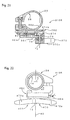
- each of the electrical shift and brake control devices 12R and 12L includes a support member or brake lever bracket 130, a brake lever 132, and a pair of electrical shift control switches 136.
- the brake cable 18a is fixedly coupled to the brake lever 132 such that the inner wire is pulled when the rider squeezes the brake lever 132.
- the brake cable 22a is fixedly coupled to the brake lever 132 of the control device 12L such that the inner wire is pulled when the rider squeezes the brake lever 132.
- the cycle computer unit 24 is electrically coupled to the first and second electrical shift control switches 136 and 138 of each of the control devices 12R and 12L via a pair of electrical cords 154.
- each of the electrical cords 154 has a pair of first electrical conductors 154a, a pair of second electrical conductors 154b and a pair of third electrical conductors 154c, which are electrical coupled to the electrical shift control switches 136 and 138.
- Each cord 154 connects one of the electrical shift control switches 136 and the electrical shift control switches 138 to the bicycle computer 24.
- a downshift signal is transmitted to the cycle computer unit 24.
- each of the electrical shift control switches 136 and 138 includes a housing 160, an operating member 161 and an electrical contact assembly 162, as seen in Figure 22 .
- the operating member 161 is rotatably coupled to the housing 160 and operatively coupled to the electrical contact assembly 162.
- the electrical contact assembly 162 mounted within the housing 160 and configured and arranged to be operated by the operating member 161.
- the construction of the electrical contact assembly 162 is the same as the electrical contact assembly 62, discussed above.
- the electrical shift control switches 136 and 138 will not be discussed or illustrated in detail herein. Rather the construction and operation of the electrical shift control switches 136 and 138 can be readily determined from the description of the electrical contact assembly 62, discussed above.
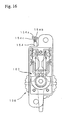
- FIG. 17 and 18 an additional bicycle shift control device 213R is illustrated in accordance with a second embodiment of the present invention is illustrated.
- This second embodiment is identical to the first embodiment of the present invention except that the computer support member 41 of the first embodiment has been replaced with a modified computer support member 241 in this second embodiment. Otherwise, this second embodiment is identical to the first embodiment. Accordingly, this second embodiment will not be discussed and/or illustrated in detail herein. Rather, it will be apparent to those skilled in the art from this disclosure that the descriptions and illustrations of the first embodiment also apply to this second embodiment, except as explained and illustrated herein. Identical parts of the first and second embodiments will be referenced with identical reference numerals.
- the modified computer support member 241 is identical to the computer support member 41 of the first embodiment, except that one of the computer support legs 40 of the first embodiment has been eliminated and the computer support member 241 is integrally formed with a handlebar mounting portion 230 of the right shift control device 213R. Accordingly, the resilient elements 44 of the first embodiment can be eliminated in this second embodiment. Moreover, the left shift control device 13L of the first embodiment is used in this second embodiment, except it does not support the bicycle computer 24.
- the handlebar mounting portion 230 of the right shift control device 213R is identical to the handlebar mounting portion 30 of the first embodiment, except that the handlebar mounting portion 230 has the computer support member 241 integrally formed therewith. Thus, the handlebar mounting portion 230 will not be discussed in further detail herein.
- the computer support member 241 basically includes a computer support leg 240 with a bicycle attachment end 240a, a computer attachment end 240b and a bent section 240c disposed between the bicycle attachment end 240a and the computer attachment end 240b.
- the computer attachment end 240b supports the computer 24 in a manner identical to the first embodiment.
- the bicycle attachment end 240a is integrally formed with a tubular clamping portion 236 of the handlebar mounting portion 230.
- the computer support leg 240 of this second embodiment is identical to the right computer support leg 40 of the first embodiment, except the left computer support leg 4-0 of the first embodiment has been eliminated and the bicycle attachment end 240a is integrally formed with a tubular clamping portion 236 of the handlebar mounting portion 230. Accordingly, this second embodiment will not be discussed in further detail herein.
- the computer support member could be integrally formed with part of the additional left shift control device instead of the additional right shift control device if needed and/or desired.
- the computer support member could be integrally formed with parts of both the left and right shift control devices if needed and/or desired.
- the computer support member should have a configuration similar to the first embodiment, but should be fixed to or integrally formed with both the handlebar support portions of the shift control devices.
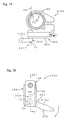
- an additional bicycle shift control device 313R is illustrated in accordance with a third embodiment of the present invention.
- the shift control device 313R illustrated herein is preferably a right side device.
- the shift control device 313R is preferably utilized in conjunction with a modified left additional shift control device (not shown) that is a mirror image of the shift control device 313R.
- the cycle computer 24 of the first and second embodiments is preferably supported by the shift control device 313R and the modified left additional shift control device (not shown) in accordance with the first embodiment or the second embodiment.
- this third embodiment is identical to the first embodiment of the present invention except that the operating member 61 with the actuator 70 of the first embodiment has been replaced with a modified operating member 361 with a modified lever-shaped actuator (element) 370 that rotates about a rotation axis 3X in this third embodiment.
- this third embodiment operates in a manner substantially identical to the first embodiment. Accordingly, this third embodiment will not be discussed and/or illustrated in detail herein. Rather, it will be apparent to those skilled in the art from this disclosure that the descriptions and illustrations of the first embodiment also apply to this third embodiment, except as explained and illustrated herein. Identical parts of the first and third embodiments will be referenced with identical reference numerals. Parts that are functionally identical will be referenced with identical reference numerals but with "300" added to them. Parts of this third embodiment that are functionally identical to parts of the first embodiment can be better understood from the descriptions and illustrations of the first embodiment, if needed.
- the operating member 361 protrudes out from a modified housing 360 such that rotational movement of the operating member 361 causes the electrical contact assembly 62 to move from a normal or rest position to one of the two actuating positions, in a manner similar to the first embodiment.
- the operating member 361 basically has the lever-shaped actuator 370, the pivot shaft 72 of the first embodiment and a modified toggle member 374.
- the actuator 370 is fixedly attached the outer end of the pivot shaft 72 by a set pin (not shown) that contacts a flat portion of the outer end of the pivot shaft 72 in a manner identical to the first embodiment.
- the actuator 370 basically includes a lever-shaped element 370a configured and arranged to facilitate engagement with the rider's thumb and/or fingers (preferably the rider's thumb).
- the inner end of the pivot shaft 72 has the toggle member 374 fixedly coupled thereto.
- rotation of the actuator 370 by the rider causes the pivot shaft 72 and the toggle member 374 to rotate therewith.
- the toggle member 374 is identical to the toggle member 74 of the first embodiment, except the toggle member 374 has a shorter radially extending projection 374b due to the location and orientation of the operating axis 3X.
- the projection 374b engages the electrical contact assembly 62 in response to rotation of the operating member 361 in a manner identical to the first embodiment.
- the toggle member 374 will not be discussed in further detail herein.
- the bearing assembly 78 that is used in the first embodiment is positioned between the housing 360 and the pivot shaft 72 such that the operating member 361 pivots or rotates smoothly about the rotational/operating axis or pivot axis 3X.
- the pivot axis 3X of the operating member 361 is non-parallel to the center axis C of the transverse portion T of the handlebar 14.
- the pivot axis 3X preferably intersects the curved mounting surface 36d of the tubular clamping portion 36.
- the biasing element (coil spring) 79 that is used in the first embodiment is also used in this embodiment.
- the biasing element 79 is positioned between the housing 360 and the toggle member 374 to normally bias the toggle member 374 to the normal rest or neutral position from the first and second actuating positions.
- the operating member 361 is normally maintained in the normal rest or neutral position, similar to the first embodiment, as discussed above.
- one end of the spring 79 is preferably received in an axial hole (not shown) of a modified base element 364 of the housing 360, while the other end of the spring 79 is preferably received in an axial hole (not shown) of the toggle member 374.
- the axial holes (not shown) and the spring 79 are preferably arranged and configured to bias the operating member 361 to the neutral rest position from first and second actuating positions in a manner identical to the first embodiment.
- the spring 79 preferably has a coiled portion with at least two coils.
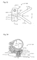
- an additional bicycle shift control device 413R is illustrated in accordance with a fourth embodiment of the present invention.
- the shift control device 413R illustrated herein is preferably a right side device.
- the shift control device 413R is preferably utilized in conjunction with a modified left additional shift control device (not shown) that is a mirror image of the shift control device 413R.
- the cycle computer 24 of the first and second embodiments is preferably supported by the shift control device 413R and the modified left additional shift control device (not shown) in accordance with the first embodiment or the second embodiment.
- this fourth embodiment is identical to the first embodiment of the present invention except that the operating member 61 with the actuator 70 of the first embodiment has been replaced with a modified operating member 461 with a modified lever-shaped actuator (element) 470 that rotates about a rotation axis 4X in this fourth embodiment.
- the inclination of the rotation axis 4X is oriented differently in this fourth embodiment relative to the center axis C of the handlebar 14 than the rotation axis X of the first embodiment.
- this fourth embodiment operates in a manner substantially identical to the first embodiment. Accordingly, this fourth embodiment will not be discussed and/or illustrated in detail herein. Rather, it will be apparent to those skilled in the art from this disclosure that the descriptions and illustrations of the first embodiment also apply to this fourth embodiment, except as explained and illustrated herein.
- Identical parts of the first and fourth embodiments will be referenced with identical reference numerals. Parts that are functionally identical will be referenced with identical reference numerals but with "400" added to them. Parts of this fourth embodiment that are functionally identical to parts of the first embodiment can be better understood from the descriptions and illustrations of the first embodiment, if needed.
- the operating member 461 protrudes out from a modified housing 460 such that rotational movement of the operating member 461 causes the electrical contact assembly 62 to move from a normal or rest position to one of the two actuating positions, in a manner similar to the first embodiment.
- the operating member 461 basically has the lever-shaped actuator 470, the pivot shaft 72 of the first embodiment and a modified toggle member 474.
- the actuator 470 is fixedly attached the outer end of the pivot shaft 72 by a set pin (not shown) that contacts a flat portion of the outer end of the pivot shaft 72 in a manner identical to the first embodiment.
- the actuator 470 basically includes a pair of finger operated lever-shaped elements 470a configured and arranged to facilitate engagement with the rider's thumb or fingers.
- the actuator 470 preferably has a V-shape as seen in Figure 23 such that one of the elements 470a can be actuated by the rider's thumb, while the other element 470a can be actuated by the rider's finger(s).
- the inner end of the pivot shaft 72 has the toggle member 474 fixedly coupled thereto.
- rotation of the actuator 470 by the rider causes the pivot shaft 72 and the toggle member 474 to rotate therewith.
- the toggle member 474 is identical to the toggle member 74 of the first embodiment, except the toggle member 474 has an axially extending part 474c extending from a radially extending projection 474b due to the location and orientation of the operating axis 4X.
- the axially extending part 474c selectively engages the electrical contact assembly 62 in response to rotation of the operating member 461 in a manner substantially identical to the first embodiment.
- the toggle member 474 will not be discussed in further detail herein.
- the bearing assembly 78 that is used in the first embodiment is positioned between the housing 460 and the pivot shaft 72 such that the operating member 461 pivots or rotates smoothly about the rotational/operating axis or pivot axis 4X.
- the pivot axis 4X of the operating member 461 is non-parallel to the center axis C of the transverse portion T of the handlebar 14.
- the pivot axis 4X preferably intersects the curved mounting surface 36d of the tubular clamping portion 36.
- the pivot axis 4X preferably substantially passes through the center axis C of the handlebar 14 to form a substantially right angle relative thereto.
- the biasing element (coil spring) 79 that is used in the first embodiment is also used in this embodiment.
- the biasing element 79 is positioned between the housing 460 and the toggle member 474 to normally bias the toggle member 474 to the normal rest or neutral position from the first and second actuating positions.
- the operating member 461 is normally maintained in the normal rest or neutral position, similar to the first embodiment, as discussed above.
- one end of the spring 79 is preferably received in an axial hole (not shown) of a modified base element 464 of the housing 460, while the other end of the spring 79 is preferably received in an axial hole (not shown) of the toggle member 474.
- the axial holes (not shown) and the spring 79 are preferably arranged and configured to bias the operating member 461 to the neutral rest position from first and second actuating positions in a manner identical to the first embodiment.
- the spring 79 preferably has a coiled portion with at least two coils.
- actuating position means a state in which an electrical connection is formed by an orientation of an operation member.
- neutral position means a state in which an electrical connection is not formed by an orientation of an operation member.
Claims (11)
- Ensemble de commande électrique de changement de vitesse pour bicyclette, comprenant :un premier dispositif de commande de changement de vitesse (13R) comprenant une première partie de montage de guidon (30) configurée pour être bloquée sur un guidon (14) et une première partie de commutation de commande électrique de changement de vitesse électrique (32) montée sur la première partie de montage de guidon (30) ; caractérisé en ce que :l'ensemble de commande électrique de changement de vitesse pour bicyclette comprend en outre une unité formant ordinateur (24) pour bicyclette, ladite unité formant ordinateur (24) pour bicyclette comprenant un écran d'affichage (56) qui est supporté par la première partie de montage de guidon (30).
- Ensemble de commande électrique de changement de vitesse pour bicyclette selon la revendication 1, comprenant en outre
un second dispositif de commande de changement de vitesse (13L) comprenant une seconde partie de montage de guidon (30) configurée pour être bloquée sur un guidon (14) et une seconde partie de commutation de commande électrique de changement de vitesse (32) montée sur la seconde partie de montage de guidon (30),
l'unité formant ordinateur (24) pour bicyclette étant supportée entre le premier et le second dispositif de commande de changement de vitesse (13R, 13L) par au moins la première partie de montage de guidon (30). - Ensemble de commande électrique de changement de vitesse pour bicyclette selon la revendication 1, dans lequel
la première partie de montage de guidon (30) comprend une section de bande (40c) et une patte de support d'ordinateur (40) s'étendant à partir de la section de bande (40c) et l'unité formant ordinateur (24) pour bicyclette est fixée sur la patte de support d'ordinateur (40) de la première partie de montage de guidon (30). - Ensemble de commande électrique de changement de vitesse pour bicyclette selon la revendication 3, dans lequel
la patte de support d'ordinateur (40) comprend une section courbée de sorte que l'unité formant ordinateur (24) pour bicyclette est décalée de manière longitudinale de la section de bande le long du guidon (14). - Ensemble de commande électrique de changement de vitesse pour bicyclette selon la revendication 1, dans lequel
la première partie de commutation de commande électrique de changement de vitesse (32) comprend un premier élément de commande (61) agencé et configuré pour se déplacer par rapport à la première partie de montage de guidon (30) entre une première position neutre et une première position d'actionnement. - Ensemble de commande électrique de changement de vitesse pour bicyclette selon la revendication 5, dans lequel
le premier élément de commande (61) est en outre agencé et configuré pour être déplacé sélectivement par rapport à la première partie de montage de guidon (30) entre la première position neutre et une seconde position d'actionnement qui est espacée de la première position d'actionnement. - Ensemble de commande électrique de changement de vitesse pour bicyclette selon la revendication 6, dans lequel
la première partie de commutation de commande électrique de changement de vitesse (32) comprend en outre un premier élément de sollicitation agencé et configuré pour pousser le premier élément de commande dans la première position neutre. - Ensemble de commande électrique de changement de vitesse pour bicyclette selon la revendication 1, dans lequel
la première partie de commutation de commande électrique de changement de vitesse (32) est couplée de manière détachable à la première partie de montage de guidon (30) de sorte que la première partie de commutation de commande électrique (32) est amovible de la première partie de montage de guidon (30) sans retirer la première partie de montage de guidon (30) du guidon (14). - Ensemble de commande électrique de changement de vitesse pour bicyclette selon la revendication 5, dans lequel
le premier élément de commande (61) de la première partie de commutation de commande électrique de changement de vitesse (32) est en outre agencé et configuré pour tourner autour d'un premier axe de commande entre la première position neutre et la première position d'actionnement. - Ensemble de commande électrique de changement de vitesse pour bicyclette selon la revendication 9, dans lequel
le premier élément de commande (61) a un premier élément de cadran avec au moins une première saillie s'étendant radialement vers l'extérieur à partir du premier élément de cadran par rapport au premier axe de commande. - Ensemble de commande électrique de changement de vitesse pour bicyclette selon la revendication 10, dans lequel
le premier élément de cadran a un élément de rebord s'étendant vers l'extérieur à partir de celui-ci qui est espacé de manière circonférentielle de la première saillie autour de l'axe de commande.
Applications Claiming Priority (2)
| Application Number | Priority Date | Filing Date | Title |
|---|---|---|---|
| US10/826,272 US7779724B2 (en) | 2004-04-19 | 2004-04-19 | Electrical bicycle shift control device |
| US826272 | 2004-04-19 |
Publications (3)
| Publication Number | Publication Date |
|---|---|
| EP1588933A2 EP1588933A2 (fr) | 2005-10-26 |
| EP1588933A3 EP1588933A3 (fr) | 2007-05-09 |
| EP1588933B1 true EP1588933B1 (fr) | 2009-07-01 |
Family
ID=34927351
Family Applications (1)
| Application Number | Title | Priority Date | Filing Date |
|---|---|---|---|
| EP04026865A Expired - Fee Related EP1588933B1 (fr) | 2004-04-19 | 2004-11-11 | Actionneur pour transmission de bicyclette commandé électriquement |
Country Status (6)
| Country | Link |
|---|---|
| US (2) | US7779724B2 (fr) |
| EP (1) | EP1588933B1 (fr) |
| JP (1) | JP4122012B2 (fr) |
| CN (1) | CN100575182C (fr) |
| DE (1) | DE602004021770D1 (fr) |
| TW (1) | TWI238800B (fr) |
Families Citing this family (45)
| Publication number | Priority date | Publication date | Assignee | Title |
|---|---|---|---|---|
| ITTO20011079A1 (it) * | 2001-11-16 | 2003-05-16 | Campagnolo Srl | ,,dispositivo di comando del cambio per una bicicletta avente un manubrio con estremita' diritte,, |
| EP1564131B1 (fr) | 2004-02-06 | 2007-08-15 | Campagnolo S.R.L. | Dispositif d'actionnement pour un câble de commande de changement de vitesse pour bicyclette |
| DE602005012075D1 (de) * | 2005-06-27 | 2009-02-12 | Campagnolo Srl | Steuerungsapparat für einen Fahrradkettenumwerfer |
| US20070137361A1 (en) * | 2005-11-18 | 2007-06-21 | Shimano Inc. | Bicycle operating component with electrical shift control switch |
| EP1976747B1 (fr) * | 2006-01-23 | 2010-08-18 | Campagnolo S.R.L. | Dispositif de commande pour dérailleur de bicyclette |
| US7503420B2 (en) * | 2006-02-01 | 2009-03-17 | Shimano Inc. | Bicycle control device |
| US20070193388A1 (en) * | 2006-02-03 | 2007-08-23 | Shimano Inc. | Bicycle shift control device |
| DE602006015158D1 (de) * | 2006-02-23 | 2010-08-12 | Campagnolo Srl | Fahrradbremsekontrollvorrichtung |
| JP4191757B2 (ja) * | 2006-10-12 | 2008-12-03 | 株式会社シマノ | 自転車用変速制御装置 |
| US7426976B2 (en) * | 2007-01-31 | 2008-09-23 | Edlin's Enterprises, Inc. | Lawn mower steering control adapter |
| ITMI20070239A1 (it) | 2007-02-09 | 2008-08-10 | Campagnolo Srl | Dispositivo di comando per un deragliatore di bicicletta |
| ITMI20070400A1 (it) * | 2007-03-01 | 2008-09-02 | Campagnolo Srl | Dispositivo di comando per bicicletta e bicicletta comprendente tale dipsositivo |
| ITMI20072230A1 (it) | 2007-11-23 | 2009-05-24 | Campagnolo Srl | Dispositivo di comando per bicicletta con manubrio ricurvo |
| US20090188340A1 (en) * | 2008-01-24 | 2009-07-30 | Shimano Inc. | Bicycle control device |
| US8212426B2 (en) * | 2008-04-21 | 2012-07-03 | Shimano Inc. | Bicycle electrical wiring unit |
| US8297143B2 (en) | 2009-05-19 | 2012-10-30 | Shimano Inc. | Electrical bicycle shift control device |
| FI20095888A0 (fi) * | 2009-08-28 | 2009-08-28 | Polar Electro Oy | Pyöräilytietokone |
| JP2011159111A (ja) * | 2010-02-01 | 2011-08-18 | Shimano Inc | 自転車用ブレーキ及び変速操作装置 |
| US9033833B2 (en) | 2011-01-28 | 2015-05-19 | Paha Designs, Llc | Gear transmission and derailleur system |
| US10207772B2 (en) | 2011-01-28 | 2019-02-19 | Paha Designs, Llc | Gear transmission and derailleur system |
| US9327792B2 (en) | 2011-01-28 | 2016-05-03 | Paha Designs, Llc | Gear transmission and derailleur system |
| US20120247252A1 (en) * | 2011-03-30 | 2012-10-04 | Wei-Hsuan Chang | Enclosing shift control device for a bicycle transmission |
| US20120247253A1 (en) * | 2011-04-01 | 2012-10-04 | Wei-Hsuan Chang | Shift control machine for a bicycle trasmission |
| US8886417B2 (en) | 2011-09-09 | 2014-11-11 | Sram, Llc | Bicycles with electronic shifting systems and methods |
| US8808123B2 (en) * | 2011-09-30 | 2014-08-19 | Shimano Inc. | Front derailleur with frame support structure |
| US8402664B1 (en) * | 2011-10-28 | 2013-03-26 | Shimano Inc. | Electric control device |
| US8979683B2 (en) * | 2012-01-31 | 2015-03-17 | Shimano Inc. | Bicycle electric actuator unit |
| US8955862B1 (en) | 2012-05-15 | 2015-02-17 | MonoMano, Inc. | Cycling control system |
| US20140061271A1 (en) * | 2012-08-29 | 2014-03-06 | Tate Labs, Inc. | Bicycle accessory mount |
| JP2015182705A (ja) * | 2014-03-26 | 2015-10-22 | 本田技研工業株式会社 | 鞍乗型車両の操作装置 |
| DE102014012421A1 (de) * | 2014-07-04 | 2016-02-11 | Invented Here B.V. | Befestigungssystem |
| US9944350B2 (en) | 2016-01-11 | 2018-04-17 | Sram, Llc | Chain guide sensor and methods of controling a bicycle |
| CN107042867B (zh) * | 2016-02-05 | 2020-10-09 | 禧玛诺(新)私人有限公司 | 自行车前拨链器 |
| US10086905B2 (en) * | 2016-03-22 | 2018-10-02 | Shimano Inc. | Bicycle front derailleur with mounting bracket |
| DE102016004329A1 (de) * | 2016-04-13 | 2017-10-19 | Sram Deutschland Gmbh | Vorrichtung zum Schalten einer elektrischen Fahrradkomponente |
| IT201600069087A1 (it) * | 2016-07-04 | 2018-01-04 | Campagnolo Srl | Deragliatore elettrico anteriore di bicicletta |
| JP6730144B2 (ja) * | 2016-09-09 | 2020-07-29 | 株式会社シマノ | 自転車用コンポーネント、および、その通信部 |
| JP6965072B2 (ja) | 2017-09-15 | 2021-11-10 | ヤマハ発動機株式会社 | 自転車及びステム組立体 |
| JP6921724B2 (ja) * | 2017-11-30 | 2021-08-18 | 株式会社シマノ | 変速制御装置および電動変速システム |
| TWI675776B (zh) * | 2018-04-13 | 2019-11-01 | 彥豪金屬工業股份有限公司 | 剎車變速組件 |
| TWI697431B (zh) * | 2019-05-08 | 2020-07-01 | 彥豪金屬工業股份有限公司 | 自行車車頭 |
| US11407475B2 (en) * | 2019-12-06 | 2022-08-09 | Shimano Inc. | Bicycle derailleur |
| US11587747B2 (en) * | 2020-11-30 | 2023-02-21 | Shimano Inc. | Operating device |
| US11643160B2 (en) * | 2020-12-29 | 2023-05-09 | Southern California Design Company | Accessory mounting system |
| CN113306666B (zh) * | 2021-06-18 | 2022-09-02 | 珠海蓝图控制器科技有限公司 | 电子变速控制器、变速系统及自行车 |
Family Cites Families (45)
| Publication number | Priority date | Publication date | Assignee | Title |
|---|---|---|---|---|
| US4032168A (en) * | 1976-02-02 | 1977-06-28 | Space-Age Control, Inc. | Handlebar riser and setback with dashboard for motorcycles |
| US4143557A (en) * | 1977-04-18 | 1979-03-13 | Sanyo Electric Co., Ltd | Control system for use in a multiple speed transmission system |
| US4489307A (en) * | 1981-05-23 | 1984-12-18 | Shimano Industrial Company Limited | Handle stem for a bicycle |
| JPS6085297U (ja) | 1983-11-17 | 1985-06-12 | スズキ株式会社 | 自動二輪車用電動変速操作装置 |
| US4900291B1 (en) * | 1988-01-06 | 2000-04-25 | Sram Corp | Bicycle gear shifting method and apparatus |
| US5400675A (en) * | 1988-11-29 | 1995-03-28 | Shimano, Inc. | Bicycle control device |
| FR2654698A1 (fr) | 1989-11-17 | 1991-05-24 | Sachs Ind Sa | Organe de direction fonctionnel et ergonomique a centrale de commande integree pour cycle. |
| DE4202323A1 (de) | 1991-01-29 | 1992-07-30 | Joerg Wunderlich | Anti-diebstahl-fahrradgangschaltsicherung (adf) |
| FR2687977B1 (fr) * | 1992-02-27 | 1994-04-22 | Bg Innovation | Dispositifs permettant les changements de vitesses sur bicyclettes. |
| IT1261090B (it) * | 1993-07-08 | 1996-05-08 | Antonio Romano | Gruppo di cambio di velocita' motorizzato per biciclette. |
| JP3470820B2 (ja) * | 1993-10-06 | 2003-11-25 | 株式会社シマノ | 自転車用変速装置 |
| EP0721905B1 (fr) * | 1994-12-12 | 2002-03-06 | Philip Morris Products S.A. | Procédé et dispositif de préparation de l'ouverture d'une bobine |
| IT1280987B1 (it) | 1995-10-19 | 1998-02-11 | Campagnolo Srl | Manubrio per bicicletta del tipo "mountain-bike" o simile, con dispositivo visualizzatore associato ad un comando cambio elettronico. |
| US6015038A (en) * | 1995-12-19 | 2000-01-18 | Otis Elevator Company | Handrail monitoring system |
| US5941125A (en) * | 1995-12-28 | 1999-08-24 | Shimano, Inc. | Bicycle shifting apparatus having remotely located levers for operating a single transmission |
| US5768945A (en) * | 1996-02-14 | 1998-06-23 | Shimano, Inc. | Extension handle for a bicycle shifting device |
| US5678455A (en) * | 1996-02-15 | 1997-10-21 | Shimano, Inc. | Bar-end shifting device |
| JP3128116B2 (ja) | 1996-12-19 | 2001-01-29 | 株式会社シマノ | 自転車用切換スイッチ |
| JP3321045B2 (ja) * | 1996-12-20 | 2002-09-03 | 株式会社シマノ | 自転車の電気的操作装置 |
| JP3510442B2 (ja) | 1997-01-14 | 2004-03-29 | 株式会社シマノ | 自転車の電気的変速操作機構 |
| JP3490250B2 (ja) * | 1997-05-14 | 2004-01-26 | ジヤトコ株式会社 | 自動変速機のセレクト制御装置 |
| JP3474080B2 (ja) * | 1997-05-16 | 2003-12-08 | 株式会社シマノ | 自転車用スイッチ |
| US6038923A (en) * | 1998-05-27 | 2000-03-21 | Giant Manufacturing Co., Ltd. | Hand-operated accelerator device for an electric-powered bicycle |
| US6305241B1 (en) | 1999-06-28 | 2001-10-23 | Shimano, Inc. | Handlebar adapter for mounting a bicycle display |
| US6227066B1 (en) * | 1999-07-26 | 2001-05-08 | Mpc Products Corporation | Joystick centering device supporting multiple compound torque profiles |
| US6204752B1 (en) * | 1999-11-24 | 2001-03-20 | Shimano Inc. | Bicycle display unit with backlight |
| US6227078B1 (en) * | 2000-02-29 | 2001-05-08 | Vincent John Lemmo, Jr. | Engine oil filter socket wrench with built-in spillage cup |
| US6331089B1 (en) * | 2000-02-29 | 2001-12-18 | Shimano, Inc. | Mounting device for bicycle component |
| US6453764B1 (en) * | 2000-03-03 | 2002-09-24 | Shimano, Inc. | Switch style bicycle shift control device |
| CN1468184A (zh) * | 2000-03-15 | 2004-01-14 | ʲ��ķ��˾ | 手柄操纵式车辆的整体式驾驶员控制系统 |
| IT1320405B1 (it) * | 2000-06-06 | 2003-11-26 | Campagnolo Srl | Dispositivo di comando elettrico per un deragliatore motorizzato perbiciclette. |
| US6584872B1 (en) * | 2000-10-31 | 2003-07-01 | Shimano Inc. | Bicycle handle mounting member |
| EP1225123B1 (fr) | 2001-01-23 | 2006-06-14 | Samuel Y.T. Strong | Accélérateur pour bicyclette électrique |
| US6546827B2 (en) * | 2001-03-28 | 2003-04-15 | Shimano Inc. | Bicycle handlebar |
| US6523772B2 (en) * | 2001-05-29 | 2003-02-25 | Shimano Inc. | Electric device with cord retainer for bicycle |
| ITTO20010555A1 (it) * | 2001-06-08 | 2002-12-08 | Campagnolo Srl | Dispositivo di comando elettrico per un deragliatore motorizzato per biciclette. |
| JP2003007778A (ja) * | 2001-06-25 | 2003-01-10 | Mitsubishi Electric Corp | 半導体装置、半導体デバイスの実装方法および半導体デバイス実装装置 |
| JP2003120803A (ja) * | 2001-10-17 | 2003-04-23 | Shimano Inc | 自転車の自動変速制御装置及びその方法 |
| US6698307B2 (en) * | 2001-10-23 | 2004-03-02 | Sram Corporation | Electronic shifter for a bicycle |
| US6734376B2 (en) | 2002-06-19 | 2004-05-11 | Shimano Inc. | Electrical switch device for bicycle |
| JP3645876B2 (ja) * | 2002-08-30 | 2005-05-11 | 株式会社シマノ | 自転車用電装品制御装置 |
| US6991081B2 (en) * | 2003-11-26 | 2006-01-31 | Shimano Inc. | Shift and break control device |
| JP2005225426A (ja) * | 2004-02-16 | 2005-08-25 | Shimano Inc | 自転車用照明装置及びそれに装着可能な自転車用表示装置。 |
| US7350436B2 (en) * | 2004-03-29 | 2008-04-01 | Shimano, Inc. | Electrical bicycle shift control device |
| US7448297B2 (en) * | 2004-08-04 | 2008-11-11 | Shimano (Singapore) Pte., Ltd | Mountable bicycle structure |
-
2004
- 2004-04-19 US US10/826,272 patent/US7779724B2/en not_active Expired - Fee Related
- 2004-09-01 TW TW093126385A patent/TWI238800B/zh active
- 2004-11-11 EP EP04026865A patent/EP1588933B1/fr not_active Expired - Fee Related
- 2004-11-11 DE DE602004021770T patent/DE602004021770D1/de active Active
- 2004-12-30 CN CN200410103704.8A patent/CN100575182C/zh not_active Expired - Fee Related
-
2005
- 2005-04-18 JP JP2005119792A patent/JP4122012B2/ja not_active Expired - Fee Related
-
2007
- 2007-02-13 US US11/674,431 patent/US20070137391A1/en not_active Abandoned
Also Published As
| Publication number | Publication date |
|---|---|
| TWI238800B (en) | 2005-09-01 |
| EP1588933A3 (fr) | 2007-05-09 |
| US20070137391A1 (en) | 2007-06-21 |
| DE602004021770D1 (de) | 2009-08-13 |
| US7779724B2 (en) | 2010-08-24 |
| JP4122012B2 (ja) | 2008-07-23 |
| CN1689904A (zh) | 2005-11-02 |
| US20050229735A1 (en) | 2005-10-20 |
| EP1588933A2 (fr) | 2005-10-26 |
| TW200535044A (en) | 2005-11-01 |
| CN100575182C (zh) | 2009-12-30 |
| JP2005306368A (ja) | 2005-11-04 |
Similar Documents
| Publication | Publication Date | Title |
|---|---|---|
| EP1588933B1 (fr) | Actionneur pour transmission de bicyclette commandé électriquement | |
| EP2402241B1 (fr) | Dispositif de commande de vitesse d'une bicyclette électrique | |
| EP1535830B1 (fr) | Dispositif de commande électrique de frein et de changement de vitesse | |
| US7908940B2 (en) | Bar end electric shifter | |
| EP2253531B1 (fr) | Dispositif électrique de commande de vitesse de bicyclette | |
| EP1787903B1 (fr) | Élément fonctionnel de bicyclette avec commutateur électrique de commande de changement de vitesse | |
| EP1816066B1 (fr) | Actionneur pour transmission de bicyclette commandé électriquement | |
| EP1816062B1 (fr) | Dispositif de commande des vitesses de bicyclette | |
| EP2075187B1 (fr) | Dispositif de changement de vitesses de bicyclette |
Legal Events
| Date | Code | Title | Description |
|---|---|---|---|
| PUAI | Public reference made under article 153(3) epc to a published international application that has entered the european phase |
Free format text: ORIGINAL CODE: 0009012 |
|
| AK | Designated contracting states |
Kind code of ref document: A2 Designated state(s): AT BE BG CH CY CZ DE DK EE ES FI FR GB GR HU IE IS IT LI LU MC NL PL PT RO SE SI SK TR |
|
| AX | Request for extension of the european patent |
Extension state: AL HR LT LV MK YU |
|
| RAP1 | Party data changed (applicant data changed or rights of an application transferred) |
Owner name: SHIMANO INC. |
|
| PUAL | Search report despatched |
Free format text: ORIGINAL CODE: 0009013 |
|
| AK | Designated contracting states |
Kind code of ref document: A3 Designated state(s): AT BE BG CH CY CZ DE DK EE ES FI FR GB GR HU IE IS IT LI LU MC NL PL PT RO SE SI SK TR |
|
| AX | Request for extension of the european patent |
Extension state: AL HR LT LV MK YU |
|
| 17P | Request for examination filed |
Effective date: 20070626 |
|
| 17Q | First examination report despatched |
Effective date: 20071008 |
|
| AKX | Designation fees paid |
Designated state(s): DE FR IT NL |
|
| GRAP | Despatch of communication of intention to grant a patent |
Free format text: ORIGINAL CODE: EPIDOSNIGR1 |
|
| GRAS | Grant fee paid |
Free format text: ORIGINAL CODE: EPIDOSNIGR3 |
|
| GRAA | (expected) grant |
Free format text: ORIGINAL CODE: 0009210 |
|
| AK | Designated contracting states |
Kind code of ref document: B1 Designated state(s): DE FR IT NL |
|
| REF | Corresponds to: |
Ref document number: 602004021770 Country of ref document: DE Date of ref document: 20090813 Kind code of ref document: P |
|
| PLBE | No opposition filed within time limit |
Free format text: ORIGINAL CODE: 0009261 |
|
| STAA | Information on the status of an ep patent application or granted ep patent |
Free format text: STATUS: NO OPPOSITION FILED WITHIN TIME LIMIT |
|
| 26N | No opposition filed |
Effective date: 20100406 |
|
| PGFP | Annual fee paid to national office [announced via postgrant information from national office to epo] |
Ref country code: FR Payment date: 20131108 Year of fee payment: 10 |
|
| PGFP | Annual fee paid to national office [announced via postgrant information from national office to epo] |
Ref country code: NL Payment date: 20141010 Year of fee payment: 11 |
|
| REG | Reference to a national code |
Ref country code: FR Ref legal event code: ST Effective date: 20150731 |
|
| PG25 | Lapsed in a contracting state [announced via postgrant information from national office to epo] |
Ref country code: FR Free format text: LAPSE BECAUSE OF NON-PAYMENT OF DUE FEES Effective date: 20141201 |
|
| REG | Reference to a national code |
Ref country code: NL Ref legal event code: MM Effective date: 20151201 |
|
| PG25 | Lapsed in a contracting state [announced via postgrant information from national office to epo] |
Ref country code: NL Free format text: LAPSE BECAUSE OF NON-PAYMENT OF DUE FEES Effective date: 20151201 |
|
| PGFP | Annual fee paid to national office [announced via postgrant information from national office to epo] |
Ref country code: IT Payment date: 20161122 Year of fee payment: 13 |
|
| PG25 | Lapsed in a contracting state [announced via postgrant information from national office to epo] |
Ref country code: IT Free format text: LAPSE BECAUSE OF NON-PAYMENT OF DUE FEES Effective date: 20171111 |
|
| PGFP | Annual fee paid to national office [announced via postgrant information from national office to epo] |
Ref country code: DE Payment date: 20181030 Year of fee payment: 15 |
|
| REG | Reference to a national code |
Ref country code: DE Ref legal event code: R119 Ref document number: 602004021770 Country of ref document: DE |
|
| PG25 | Lapsed in a contracting state [announced via postgrant information from national office to epo] |
Ref country code: DE Free format text: LAPSE BECAUSE OF NON-PAYMENT OF DUE FEES Effective date: 20200603 |