EP1588150B1 - Infrarotquelle und gassensor - Google Patents
Infrarotquelle und gassensor Download PDFInfo
- Publication number
- EP1588150B1 EP1588150B1 EP03782147A EP03782147A EP1588150B1 EP 1588150 B1 EP1588150 B1 EP 1588150B1 EP 03782147 A EP03782147 A EP 03782147A EP 03782147 A EP03782147 A EP 03782147A EP 1588150 B1 EP1588150 B1 EP 1588150B1
- Authority
- EP
- European Patent Office
- Prior art keywords
- transmission
- layer
- infrared source
- wavelength
- filter
- Prior art date
- Legal status (The legal status is an assumption and is not a legal conclusion. Google has not performed a legal analysis and makes no representation as to the accuracy of the status listed.)
- Expired - Lifetime
Links
- 230000005540 biological transmission Effects 0.000 claims abstract description 107
- 239000011521 glass Substances 0.000 claims description 17
- 238000010521 absorption reaction Methods 0.000 claims description 13
- 229910052732 germanium Inorganic materials 0.000 claims description 7
- GNPVGFCGXDBREM-UHFFFAOYSA-N germanium atom Chemical compound [Ge] GNPVGFCGXDBREM-UHFFFAOYSA-N 0.000 claims description 6
- 229910052710 silicon Inorganic materials 0.000 claims description 6
- 239000010703 silicon Substances 0.000 claims description 5
- 230000000694 effects Effects 0.000 abstract description 3
- 239000007789 gas Substances 0.000 description 29
- 230000005855 radiation Effects 0.000 description 20
- CURLTUGMZLYLDI-UHFFFAOYSA-N Carbon dioxide Chemical compound O=C=O CURLTUGMZLYLDI-UHFFFAOYSA-N 0.000 description 6
- XUIMIQQOPSSXEZ-UHFFFAOYSA-N Silicon Chemical compound [Si] XUIMIQQOPSSXEZ-UHFFFAOYSA-N 0.000 description 5
- 238000010438 heat treatment Methods 0.000 description 5
- 239000000463 material Substances 0.000 description 5
- 238000010586 diagram Methods 0.000 description 4
- 238000005259 measurement Methods 0.000 description 4
- 229910002092 carbon dioxide Inorganic materials 0.000 description 3
- 239000001569 carbon dioxide Substances 0.000 description 3
- 239000012528 membrane Substances 0.000 description 3
- 238000002834 transmittance Methods 0.000 description 3
- 238000001514 detection method Methods 0.000 description 2
- 239000004065 semiconductor Substances 0.000 description 2
- 238000011481 absorbance measurement Methods 0.000 description 1
- 238000004378 air conditioning Methods 0.000 description 1
- 230000015572 biosynthetic process Effects 0.000 description 1
- 239000011248 coating agent Substances 0.000 description 1
- 238000000576 coating method Methods 0.000 description 1
- 229910001610 cryolite Inorganic materials 0.000 description 1
- 230000001419 dependent effect Effects 0.000 description 1
- 238000001914 filtration Methods 0.000 description 1
- -1 for example Substances 0.000 description 1
- 150000002290 germanium Chemical class 0.000 description 1
- 238000009434 installation Methods 0.000 description 1
- 230000002452 interceptive effect Effects 0.000 description 1
- 238000004519 manufacturing process Methods 0.000 description 1
- 239000002184 metal Substances 0.000 description 1
- 238000000034 method Methods 0.000 description 1
- 230000003287 optical effect Effects 0.000 description 1
- 239000010453 quartz Substances 0.000 description 1
- 230000029058 respiratory gaseous exchange Effects 0.000 description 1
- 230000000630 rising effect Effects 0.000 description 1
- VYPSYNLAJGMNEJ-UHFFFAOYSA-N silicon dioxide Inorganic materials O=[Si]=O VYPSYNLAJGMNEJ-UHFFFAOYSA-N 0.000 description 1
- 239000000126 substance Substances 0.000 description 1
- 239000000758 substrate Substances 0.000 description 1
- 229920001169 thermoplastic Polymers 0.000 description 1
- 239000004416 thermosoftening plastic Substances 0.000 description 1
Images


Classifications
-
- H—ELECTRICITY
- H01—ELECTRIC ELEMENTS
- H01K—ELECTRIC INCANDESCENT LAMPS
- H01K1/00—Details
- H01K1/28—Envelopes; Vessels
- H01K1/32—Envelopes; Vessels provided with coatings on the walls; Vessels or coatings thereon characterised by the material thereof
-
- G—PHYSICS
- G01—MEASURING; TESTING
- G01J—MEASUREMENT OF INTENSITY, VELOCITY, SPECTRAL CONTENT, POLARISATION, PHASE OR PULSE CHARACTERISTICS OF INFRARED, VISIBLE OR ULTRAVIOLET LIGHT; COLORIMETRY; RADIATION PYROMETRY
- G01J3/00—Spectrometry; Spectrophotometry; Monochromators; Measuring colours
- G01J3/02—Details
- G01J3/10—Arrangements of light sources specially adapted for spectrometry or colorimetry
- G01J3/108—Arrangements of light sources specially adapted for spectrometry or colorimetry for measurement in the infrared range
-
- G—PHYSICS
- G01—MEASURING; TESTING
- G01N—INVESTIGATING OR ANALYSING MATERIALS BY DETERMINING THEIR CHEMICAL OR PHYSICAL PROPERTIES
- G01N21/00—Investigating or analysing materials by the use of optical means, i.e. using sub-millimetre waves, infrared, visible or ultraviolet light
- G01N21/17—Systems in which incident light is modified in accordance with the properties of the material investigated
- G01N21/25—Colour; Spectral properties, i.e. comparison of effect of material on the light at two or more different wavelengths or wavelength bands
- G01N21/31—Investigating relative effect of material at wavelengths characteristic of specific elements or molecules, e.g. atomic absorption spectrometry
- G01N21/35—Investigating relative effect of material at wavelengths characteristic of specific elements or molecules, e.g. atomic absorption spectrometry using infrared light
- G01N21/3504—Investigating relative effect of material at wavelengths characteristic of specific elements or molecules, e.g. atomic absorption spectrometry using infrared light for analysing gases, e.g. multi-gas analysis
Definitions
- the invention is based on an infrared source and a gas sensor according to the preamble of the independent claims.
- devices for the detection of radiation signals which serve for example for determining the gas concentration by means of infrared absorption.
- Disturbing gases in a gas volume for example in the interior of a motor vehicle, for example, CO 2 , CO, H 2 O or CH 4 , wherein the carbon dioxide CO 2 in particular from the breathing air of persons located in the gas volume or from CO 2 air conditioning can come.
- Such interfering gases are detected according to well-known gas detectors.
- Such sensors for the selection of gases which are based on the principle of radiation absorption in the measurement gas, usually consist of a radiation source and one or more wavelength-specific radiation detectors.
- thermal radiators are usually used as the source.
- the wavelength-specific radiation detectors consist of a filter unit which transmits the wavelength to be measured and a broadband infrared detector.
- interference filters are used here as filters. Simple interference filters have the property of also transmitting harmonic of the desired wavelength.
- the US 3,211,961 A describes a gas sensor with an infrared source, an infrared detector and a filter system arranged in front of the detector, consisting of an interference filter and a long-pass filter, which filters away wavelengths smaller than 2 ⁇ m.
- the WO 00/04351 A discloses an infrared source for gas sensors encapsulated in a flask of infra-red transmissive glass.
- the US 3,331,941 A describes an infrared source with a heating coil mounted in a housing, the housing having on the exit side of the radiation a quartz window with a first transmission characteristic coated with a layer system of alternating germanium and cryolite layers having a second transmission characteristic.
- the combination of these two transmission characteristics results in a bandpass filter characteristic in an operating frequency range of 2.85-3.8 ⁇ m.
- This infrared source is used in a device for forming thermoplastic films.
- the infrared source according to the invention and the gas sensor with the features of the independent claims have the advantage over the past that no additional installation effort is necessary in the production of the sensor and yet a broadband filter between the infrared source and the infrared detector is provided. It is thus advantageously possible that the radiation emitted by the infrared source radiation is emitted only in the range of an operating frequency range and thus the dissipation of energy in other areas of the gas sensor is reduced. This makes it possible that the main heat development is only at the infrared source. The heat development can be removed from the detector side. Furthermore, it is thereby possible according to the invention that only radiation reaches the detector in the narrow operating frequency range around the wavelength of the interference filter.
- the measures listed in the dependent claims advantageous refinements and improvements of the infrared source and the gas sensor indicated in the independent claims are possible. It is particularly advantageous that the first transmission characteristic with respect to the operating frequency range for smaller wavelengths provides a higher transmission and that the second transmission characteristic with respect to the operating frequency range for longer wavelengths provides a higher transmission. This makes it possible to easily effect a band-pass filter characteristic for an operating frequency range. Furthermore, it is advantageous that glass is provided as the first layer and that silicon or germanium is provided as the second layer. It is possible to provide the bandpass characteristic of the invention with simple methods and materials, wherein in the case of the glass layer, the material in a conventional infrared source, already exists.
- FIG. 9 the basic structure of a gas sensor according to the invention is shown.
- an infrared source designated by the reference numeral 10 which carries a first layer 102 and a second layer 103
- an infrared radiation designated by the reference numeral 21 and an arrow is emitted in the direction of a detector 30.
- a gas is provided, which is provided with the reference numeral 20.
- the gas comprises gas fractions whose concentration is to be measured with the gas sensor. As such a proportion of gas, for example, carbon dioxide CO 2 comes into question.
- the detector device 30 comprises an infrared detector 31 and a filter 32, both of which are fixed by a holder 33 relative to each other.
- the filter 32 transmits only such a wavelength, which corresponds to the absorption wavelength of the measurement gas to be detected in the gas 20, for example CO 2 .
- the gas concentration of the gas to be measured, for example CO 2 in the gas 20 can be derived.
- it makes sense in the invention that in addition to a in FIG. 9 illustrated arrangement of a gas sensor at the same time still a reference arrangement is provided in which a filter is arranged in front of a similar infrared detector, which is for a larger Wavelength range is permeable, so that thereby a reference measurement is feasible.
- the filter 32 is provided in particular as an interference filter.
- the filter 32 is provided as a Fabry-Perot filter.
- Such filters have the property that, in addition to the desired transmission frequency or desired transmission wavelength, further transmission frequencies or transmission wavelengths occur.
- the desired pass frequency corresponds to the absorption frequency of the substance in the gas 20, whose concentration is to be measured.
- the further Duchlassfrequenzen or transmission wavelengths of the filter 32 are in particular the harmonic of the desired transmission wavelength. According to the invention, it is prevented by simple means that undesired passage frequencies of the filter 32 reach the area of the infrared detector 31.
- the infrared source 10 is changed so that only infrared radiation 21 can escape in a narrow range around the desired transmission frequency or transmission wavelength of the interference filter 32.
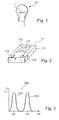
- FIG. 1 For example, a conventional infrared source 10 for an incandescent infrared radiator is shown.
- an incandescent filament 1 which is heated to a corresponding temperature, generates radiation which also comprises infrared components.
- the filament is provided according to the prior art with a surrounding glass body.
- a conventional infrared source 11 is shown in the form of a micromechanical infrared radiator.
- the micromechanical infrared source 11 comprises a substrate 111, on which in particular a membrane or a membrane region 112 and in the membrane region 112 a heating structure 113 is provided.
- the heating structure 113 which is also designated as heating device 113, is provided by means of the reference numeral 114 Pads and not specifically provided with a reference numeral connecting lines from outside the micromechanical infrared source 11 (electrically) accessible or controllable.
- the heater 113 similar to the heating coil 1 in the conventional infrared source according to FIG. 1 , heated by an electric current flowing through them, and thereby generates the radiation, which also has infrared components.
- FIG. 3 is the transmission curve of a conventional interference filter shown.
- the wavelength is shown and on the ordinate provided with the reference numeral 70, the transmittance in% is indicated.
- a first transmittance of 100% indicated by reference numeral 71 is achieved only at excellent wavelengths.
- the transmission curve 600 has maxima at such excellent wavelengths. It thus decays into a number of transmission partial curves centered around certain wavelengths, of which in FIG. 3 2, a first filter transmission part curve 610 and a second filter transmission part curve 620 are shown.
- the first filter transmission part curve 610 is centered around the first pass wavelength of the filter corresponding to the eleventh wavelength 61.
- the second filter transmission part curve 620 is centered around a twelfth wavelength, which is designated by reference numeral 62.
- the eleventh and twelfth wavelengths 61, 62 result from twice the optical thickness of the material of the interference filter divided by an integer number, where the integer number can be 1.2 and so on.
- FIG. 4 the filter transmission curve and the transmission characteristic of the radiation emitted by an infrared source 10 according to the invention are shown.
- the wavelength is plotted and on the ordinate provided with the reference numeral 70, the degree of transmission in% is indicated.
- the characteristic of the radiation emitted by a source according to the invention is designated by the reference numeral 500 and a dashed line. This assumes significant values only in a range that includes only a maximum of the filter transmission curve.
- the entire filter transmission curve is in FIG.
- the entire filter transmission curve 600 includes the first filter transmission part curve 610 at the eleventh wavelength 61, the second filter transmission part curve 620 at the twelfth wavelength 62, a third filter transmission part curve 630 at the thirteenth wavelength 63, a fourth filter transmission part curve 640 at the fourteenth wavelength 64 and a fifth filter transmission part curve 650 at the fifteenth wavelength 65.
- the maximum of the transmission of 100% is designated by the first transmittance 71.
- the eleventh wavelength 61 is plotted approximately in the central region of the illustrated abscissa 50, ie the axis of the wavelengths. To the right and left thereof, ie in the direction of the larger wavelengths and in the direction of the smaller wavelengths, the next maxima of the filter transmission curve 600 are at the twelfth wavelength 62 and at the fourteenth wavelength 64 respectively.
- the characteristic 500 is that of the According to the infrared source 10 of the invention radiated radiation, wherein in the lower part of the FIG. 4 the region of the operating frequencies or of the operating wavelengths provided with a double arrow and the reference numeral 501 corresponds approximately to the region of appreciable values of the characteristic 500 of the radiation emitted by the infrared source 10 according to the invention.
- the infrared source 10 according to the invention is provided as an incandescent lamp with an incandescent filament 101 and connecting wires 104.
- a glass lamp body 102 made of glass is provided, which serves as the first layer 102.
- a further absorption layer 103 applied to this lamp glass body 102 is referred to as a second layer.
- the absorption characteristic of the lamp glass 102 and on the other hand the absorption characteristic of the additionally applied coating 103 of the lamp glass 102 is utilized.
- the advantage of this structure lies in the use of the lamp glass 102 as part of the absorption filter, namely as a first layer 102 and further as a support for a further absorption filter layer 103, ie the second layer 103.
- a lamp glass is typically used, which exhibits a transmission up to a wavelength of about 5 microns.
- This absorption characteristic has the effect that the longer-wave Hannonas of the interference filter 32 are no longer significant at the detector 30 because they are not affected by the first layer 102, ie, from the lamp glass body 102, are absorbed.
- the shorter wavelength portions of the light emitted by the filament 101 must be filtered out to form a, as in FIG. 4 shown, band-limited transmission characteristic 500 of the combination of the first and second layers 102, 103 to arrive.
- Suitable for this purpose are semiconductor materials such as silicon or germanium, which can be vapor-deposited as a second layer 103 on the surface of the first layer 102, ie on the surface of the glass body 102 of the incandescent lamp.
- semiconductor materials it is also possible, for example, to apply metal layers or organic absorption layers to the surface of the first layer 102.
- the transmission characteristic 510 of the first layer 102 is shown.
- the transmission characteristic 510 of the first layer 102 is shown as so-called first transmission characteristic 510.
- a third wavelength 53 which is for example 2.5 ⁇ m
- a second transmission rate 72 of approximately 90% results.
- the transmission 70 drops off to greater wavelengths, resulting in a second wavelength 52 of about 4 microns, a local maximum of the transmission characteristic of about 60% transmission and with larger wavelengths towards a relatively large drop in transmission is observed, at a sixth wavelength 56 of about 5 microns, the transmission is approximately 0.
- the transmission remains close to 0% for wavelengths greater than the sixth wavelength 56 and, for smaller wavelengths than the third wavelength 53, remains at about the level of the second transmission rate 72 of approximately 90%.
- FIG. 8 is shown in a further diagram, the combination of the first and second transmission characteristic together with a filter transmission curve of the interference filter.
- the abscissa 50 again forms a wavelength scale and the ordinate 70 a scale of the transmission rate.
- the first transmission characteristic 510 is in FIG. 8 represented by a dashed line, it corresponds to the in FIG. 6 transmission characteristic for glass, wherein below the third wavelength 53, ie for wavelengths smaller than the third wavelength 53, the transmission level is very high, wherein between the third wavelength 53 and the sixth wavelength 56, a drop in transmission to near 0 of the first transmission characteristic 510th is shown.
- the second transmission characteristic 520 is indicated by a dashed line in FIG FIG.
- a superimposition of the two transmission characteristics gives the bandpass filter characteristic according to the invention, which in FIG. 8 is denoted by the reference numeral 500 and the two falling or rising branches of the first and second transmission characteristic 510, 520 includes.
- Such a bandpass filter characteristic 500 results from the in FIG. 5 shown superposition of the first layer 102 and the second layer 103 to the infrared source 10.
- the superposition in FIG. 8 the bandpass filter characteristic 500 with the filter transmission curve 600 of the interference filter 32 shows that the
- Operating frequency range in FIG. 8 indicated by the reference numeral 501 and a double arrow, comprises only a single pass frequency of the interference filter 32.
- This transmission frequency corresponds to the eleventh wavelength 61 around which the first filter transmission part curve 610 is arranged.
- the further adjacent filter transmission sections 620, 640 located at the twelfth and fourteenth wavelengths 62, 64 are outside the operating frequency range 501.
Landscapes
- Physics & Mathematics (AREA)
- Spectroscopy & Molecular Physics (AREA)
- General Physics & Mathematics (AREA)
- Biochemistry (AREA)
- Chemical & Material Sciences (AREA)
- Analytical Chemistry (AREA)
- Life Sciences & Earth Sciences (AREA)
- General Health & Medical Sciences (AREA)
- Health & Medical Sciences (AREA)
- Immunology (AREA)
- Pathology (AREA)
- Investigating Or Analysing Materials By Optical Means (AREA)
- Inspection Of Paper Currency And Valuable Securities (AREA)
Description
- Die Erfindung geht aus von einer Infrarotquelle und einem Gassensor nach der Gattung der nebengeordneten Ansprüche. Es sind bereits Vorrichtungen zur Detektion von Strahlungssignalen bekannt, die beispielsweise zur Bestimmung der Gaskonzentration mittels Infrarotabsorption dienen. Störende Gase in einem Gasvolumen, beispielsweise im Innenraum eines Kraftfahrzeuges, sind beispielsweise CO2, CO, H2O oder auch CH4, wobei das Kohlendioxid CO2 insbesondere aus der Atemluft von in dem Gasvolumen befindlichen Personen bzw. auch aus CO2-Klimaanlagen stammen kann. Solche störenden Gase werden gemäß allgemein bekannten Gasdetektoren detektiert. Solche Sensoren für die Selektion von Gasen, die auf dem Prinzip der Strahlungsabsorption im Messgas basieren, bestehen üblicherweise aus einer Strahlungsquelle und einem oder mehreren wellenlängenspezifischen Strahlungsdetektoren. Für Sensoren, die die Absorption im mittleren Infrarotbereich, beispielsweise im Bereich von Wellenlängen von 3 µm bis 25 µm messen, wie beispielsweise Sensoren zur Detektion von Kohlenstoffdioxid CO2, werden üblicherweise thermische Strahler als Quelle verwendet. Hier gibt es beispielsweise als Infrarotquellen Strahler in Form von Glühlampen oder in Form von mikrostrukturierten Anordnungen, die als thermische Strahler fungieren. Die wellenlängenspezifischen Strahlungsdetektoren bestehen aus einer Filtereinheit, die die zu messende Wellenlänge transmittiert und einem breitbandigen Infrarotdetektor. Als Filter kommen hier beispielsweise Interferenzfilter zum Einsatz. Einfache Interferenzfilter haben die Eigenschaft, auch harmonische der gewünschten Wellenlänge zu transmittieren. Dies kann zum einen durch einen komplizierteren und damit auch einem kostenintensiveren Aufbau des Interferenzfilters behoben werden, oder aber durch dem Einsatz eines einfachen Breitbandfilters vor den eigentlichen Detektor. Wird ein solches Breitbandfilter verwendet, so bedingt dies einen aufwändigen Aufbau des Detektors, da dann zwei Filter montiert werden müssen.
- Die
US 3,211,961 A beschreibt einen Gassensor mit einer Infrarotquelle, einem Infrarot-Detektor und einem vor dem Detektor angeordneten Filtersystem bestehend aus einem Interferenzfilter und einem Langpaßfilter, der Wellenlängen kleiner als 2 µm wegfiltert. - Die
WO 00/04351 A - Die
US 3,331,941 A beschreibt eine Infrarotquelle mit einer in einem Gehäuse angebrachten Heizspirale, wobei das Gehäuse auf der Austrittsseite der Strahlung ein Quartzfenster mit einer ersten Transmissionscharakteristik aufweist, das mit einem Schichtsystem aus alternierenden Germanium- und Kryolith-Schichten mit einer zweiten Transmissionscharakteristik beschichtet ist. Die Kombination dieser beiden Transmissionscharakteristiken führt zu einer Bandpaßfiltercharakteristik in einem Betriebsfrequenzbereich von 2.85-3.8 µm. Diese Infrarotquelle wird in einer Vorrichtung zur Umformung thermoplastischer Folien eingesetzt. - Die erfindungsgemäße Infrarotquelle und der Gassensor mit den Merkmalen der nebengeordneten Ansprüche haben dem gegenüber den Vorteil, dass kein zusätzlicher Montageaufwand bei der Fertigung des Sensors notwendig ist und trotzdem ein breitbandiges Filter zwischen der Infrarotquelle und dem Infrarotdetektor vorgesehen ist. Es ist damit vorteilhaft möglich, dass die von der Infrarotquelle ausgehende Strahlung nur im Bereich eines Betriebsfrequenzbereichs abgestrahlt wird und so auch die Dissipation der Energie in anderen Bereichen des Gassensors verringert wird. Hierdurch ist es möglich, dass die Hauptwärmeentwicklung nur bei der Infrarotquelle liegt. Die Wärmeentwicklung kann dabei von der Detektorseite entfernt werden. Weiterhin ist es dadurch erfindungsgemäß möglich, dass nur Strahlung in dem engen Betriebsfrequenzbereich um die Wellenlänge des Interferenzfilters herum überhaupt in Richtung des Detektors gelangt.
- Durch die in den Unteransprüchen aufgeführten Maßnahmen sind vorteilhafte Weiterbildungen und Verbesserungen der in den nebengeordneten Ansprüchen angegebenen Infrarotquelle und des Gassensors möglich. Besonders vorteilhaft ist, dass die erste Transmissionscharakteristik bezüglich des Betriebsfrequenzbereichs für kleinere Wellenlängen eine höhere Transmission vorsieht und dass die zweite Transmissionscharakteristik bezüglich des Betriebsfrequenzbereichs für größere Wellenlängen eine höhere Transmission vorsieht. Dadurch ist es möglich, auf einfache Weise eine Bandpassfiltercharakteristik für einen Betriebsfrequenzbereich zu bewirken. Weiterhin ist von Vorteil, dass als erste Schicht Glas vorgesehen ist und dass als zweite Schicht Silizium oder Germanium vorgesehen ist. Dabei ist es möglich, die erfindungsgemäße Bandpasscharakteristik mit einfachen Methoden und Materialien vorzusehen, wobei für den Fall der Glasschicht das Material bei einer herkömmlichen Infrarotquelle, bereits vorhanden ist.
- Ausführungsbeispiele der Erfindung sind in den Zeichnungen dargestellt und in der nachfolgenden Beschreibung näher erläutert. Es zeigen
-
Figur 1 eine herkömmliche Infrarotquelle in Glühlampenform, -
Figur 2 eine herkömmliche Infrarotquelle in Form eines mikromechanischen Infrarotstrahlers, -
Figur 3 die Transmissionskurve eines üblichen Interferenzfilters, -
Figur 4 die Filtertransmissionskurve und die Transmissionscharakteristik der von einer erfindungsgemäßen Infrarotquelle abgestrahlten Strahlung, -
Figur 5 eine erfindungsgemäße Infrarotquelle, -
Figur 6 die Transmissionscharakteristik einer ersten Schicht, -
Figur 7 die Transmissionscharakteristik einer zweiten Schicht, -
Figur 8 die Kombination der Transmissionscharakteristik mit einer Filtertransmissionskurve und -
Figur 9 den prinzipiellen Aufbau eines erfindungsgemäßen Gassensors. - In
Figur 9 ist der prinzipielle Aufbau eines erfindungsgemäßen Gassensors dargestellt. Ausgehend von einer mit dem Bezugszeichen 10 bezeichneten Infrarotquelle, die eine erste Schicht 102 und eine zweite Schicht 103 trägt, wird eine mit dem Bezugszeichen 21 und einem Pfeil bezeichnete Infrarotstrahlung in Richtung auf einen Detektor 30 hin ausgesandt. Im Bereich zwischen der Infrarotquelle 10 und dem Detektor 30 ist ein Gas vorhanden, welches mit dem Bezugszeichen 20 versehen ist. Das Gas umfasst Gasanteile, deren Konzentration mit dem Gassensor zu messen sind. Als ein solcher Gasanteil kommt beispielsweise Kohlenstoffdioxid CO2 in Frage. Die Detektorvorrichtung 30 umfasst einen Infrarotdetektor 31 und ein Filter 32, welche beide durch eine Halterung 33 relativ zueinander fixiert sind. Das Filter 32 lässt erfindungsgemäß lediglich eine solche Wellenlänge durch, welche der Absorptionswellenlänge des im Gas 20 zu detektierenden Messgases, beispielsweise CO2, entspricht. Aus dem Grad der Abschwächung der von der Infrarotquelle, ausgehenden Infrarotstrahlung 21 für die Messwellenlängen bzw. die Detektionswellenlänge kann die Gaskonzentration des zu messenden Gases, beispielsweise CO2, im Gas 20 abgeleitet werden. Hierzu ist es erfindungsgemäß sinnvoll, dass neben einer inFigur 9 dargestellten Anordnung eines Gassensors gleichzeitig noch eine Referenzanordnung vorgesehen ist, bei der vor einem ähnlichen Infrarotdetektor ein Filter angeordnet ist, welches für einen größeren Wellenlängenbereich durchlässig ist, so dass hierdurch eine Referenzmessung durchführbar ist. - Bei dem in
Figur 9 dargestellten Gassensor ist das Filter 32 insbesondere als Interferenzfilter vorgesehen. Beispielhaft ist das Filter 32 als Fabry-Perot-Filter vorgesehen. Solche Filter haben die Eigenschaft, dass neben der gewünschten Durchlassfrequenz bzw. gewünschten Durchlasswellenlänge noch weitere Durchlassfrequenzen bzw. Durchlasswellenlängen auftreten. Die gewünschte Durchlassfrequenz entspricht hierbei der Absorptionsfrequenz des Stoffes in dem Gas 20, dessen Konzentration zu messen ist. Die weiteren Duchlassfrequenzen bzw. Durchlasswellenlängen des Filter 32 sind insbesondere die harmonischen der gewünschten Durchlasswellenlänge. Erfindungsgemäß wird mit einfachen Mitteln verhindert, dass nicht gewünschte Durchlassfrequenzen des Filters 32 in den Bereich des Infrarotdetektors 31 gelangen. Hierzu ist es erfindungsgemäß vorgesehen, nennenswerte Anteile der Infrarotstrahlung 21 bei diesen nicht gewünschten Durchlassfrequenzen bereits kurz nach ihrer Entstehung, d.h. bei der Quelle 10, an ihrer weiteren Ausbreitung Richtung dem Filter 32 bzw. des Infrarotdetektors 31 zu behindern. Eine Anordnung, bei der eine solche Ausfilterung von ungewünschten Durchlassfrequenzen direkt vor oder nach dem Filter 32 erfolgt, wird dabei erfindungsgemäß vermieden, weil dies mit hohen Kosten und großem Aufwand hinsichtlich des Aufbaus des Detektors 30 verbunden ist. Erfindungsgemäß wird daher die Infrarotquelle 10 so verändert, dass nur Infrarotstrahlung 21 in einem engen Bereich um die gewünschte Durchlassfrequenz bzw. Durchlasswellenlänge des Interferenzfilters 32 austreten kann. - In
Figur 1 ist eine herkömmliche Infrarotquelle 10 für einen Infrarotstrahler in Glühlampenform dargestellt. Hierbei erzeugt eine Glühwendel 1, die auf eine entsprechende Temperatur geheizt ist, eine Strahlung, die auch Infrarotanteile umfasst. Die Glühwendel wird gemäß dem Stand der Technik mit einem umgebenden Glaskörper versehen. - In
Figur 2 ist eine herkömmliche Infrarotquelle 11 in Form eines mikromechanischen Infrarotstrahlers dargestellt. Die mikromechanische Infrarotquelle 11 umfasst ein Substrat 111, auf dem insbesondere eine Membran bzw. ein Membranbereich 112 und im Membranbereich 112 eine Heizstruktur 113 vorgesehen ist. Die auch als Heizeinrichtung 113 bezeichnete Heizstruktur 113 ist mittels mit dem Bezugszeichen 114 versehenen Anschlussflächen und nicht eigens mit einem Bezugszeichen versehenen Verbindungsleitungen von außerhalb der mikromechanischen Infrarotquelle 11 (elektrisch) zugänglich bzw. steuerbar. Die Heizeinrichtung 113 wird, ähnlich wie die Heizwendel 1 bei der herkömmlichen Infrarotquelle gemäßFigur 1 , durch einen elektrischen Strom, der durch sie fließt, aufgeheizt und erzeugt dadurch die Strahlung, welche auch Infrarotanteile aufweist. - In
Figur 3 ist die Transmissionskurve eines üblichen Interferenzfilters dargestellt. Auf der mit dem Bezugszeichen 50 bezeichneten Abszisse ist die Wellenlänge dargestellt und auf der mit dem Bezugszeichen 70 versehenen Ordinate ist der Transmissionsgrad in % angegeben. Eine erster Transmissionsgrad von 100 %, der mit dem Bezugszeichen 71 angegeben ist, wird nur bei ausgezeichneten Wellenlängen erreicht. Die Transmissionskurve 600 weist bei solchen ausgezeichneten Wellenlängen Maxima auf. Sie zerfällt damit in eine Anzahl von um bestimmte Wellenlängen herum zentrierte Transmissionsteilkurven, wovon inFigur 3 lediglich zwei dargestellt sind, eine erste Filtertransmissionsteilkurve 610 und eine zweite Filtertransmissionsteilkurve 620. Die erste Filtertransmissionsteilkurve 610 ist um die erste Durchgangswellenlänge des Filters, welche der elften Wellenlänge 61 entspricht, herum zentriert. Die zweite Filtertransmissionteilkurve 620 ist um eine zwölfte Wellenlänge, welche mit dem Bezugszeichen 62 versehen ist, herum zentriert. Die elfte und zwölfte Wellenlänge 61, 62 ergeben sich aus dem doppelten der optischen Dicke des Materials des Interferenzfilters, geteilt durch eine ganzzahlige Zahl, wobei die ganzzahlige Zahl die Werte 1,2 usw. annehmen kann. - In
Figur 4 ist die Filtertransmissionskurve und die Transmissionscharakteristik der von einer erfindungsgemäßen Infrarotquelle 10 abgestrahlten Strahlung dargestellt. Auf der mit dem Bezugszeichen 50 versehenen Abszisse ist wiederum die Wellenlänge aufgetragen und auf der mit dem Bezugszeichen 70 versehenen Ordinate ist der Grad der Transmission in % angegeben. Die Charakteristik der von einer erfindungsgemäßen Quelle abgestrahlten Strahlung ist mit dem Bezugszeichen 500 und einer gestrichelten Linie bezeichnet. Diese nimmt nennenswerte Werte lediglich in einem Bereich an, der nur ein Maximum der Filtertransmissionskurve umfasst. Die gesamte Filtertransmissionskurve ist inFigur 4 anhand mehrerer Filtertransmissionsteilkurven zu der elften Wellenlänge 61, zu der zwölften Wellenlänge 62, zu einer dreizehnten Wellenlänge 63, zu einer vierzehnten Wellenlänge 64 und zu einer fünfzehnten Wellenlänge 65 dargestellt. Die gesamte Filtertransmissionskurve 600, wobei das Bezugszeichen 600 inFigur 4 nicht dargestellt ist, umfasst die erste Filtertransmissionsteilkurve 610 zur elften Wellenlänge 61, die zweite Filtertransmissionsteilkurve 620 zur zwölften Wellenlänge 62, eine dritte Filtertransmissionsteilkurve 630 zur dreizehnten Wellenlänge 63, eine vierte Filtertransmissionsteilkurve 640 zur vierzehnten Wellenlänge 64 und eine fünfte Filtertransmissionsteilkurve 650 zur fünfzehnten Wellenlänge 65. Wiederum ist das Maximum der Transmission von 100 % mit dem ersten Transmissionsgrad 71 bezeichnet. InFigur 4 ist die elften Wellenlänge 61 etwa im mittleren Bereich der dargestellten Abszisse 50, d.h. der Achse der Wellenlängen, aufgetragen. Rechts und links hiervon, d.h. in Richtung der größeren Wellenlängen und in Richtung der kleineren Wellenlängen sind die nächsten Maxima der Filtertransmissionskurve 600 bei der zwölften Wellenlänge 62 bzw. bei der vierzehnten Wellenlänge 64. Um die elfte Wellenlänge 61 herum ist die Charakteristik 500 der von der erfindungsgemäßen Infrarotquelle 10 abgestrahlten Strahlung dargestellt, wobei im unteren Bereich derFigur 4 der mit einem Doppelpfeil und dem Bezugszeichen 501 versehene Bereich der Betriebsfrequenzen bzw. der Betriebswellenlängen etwa mit dem Bereich nennenswerter Werte der Charakteristik 500 der von der erfindungsgemäßen Infrarotquelle 10 abgestrahlten Strahlung übereinstimmt. - In
Figur 5 ist eine erfindungsgemäße Infrarotquelle 10 dargestellt. Hierbei wird die erfindungsgemäße Infrarotquelle 10 als Glühlampe mit einer Glühwendel 101 und Anschlussdrähten 104 vorgesehen. Um die Glühwendel 101 herum ist ein Lampenglaskörper 102 aus Glas vorgesehen, der als erste Schicht 102 dient. Eine auf diesem Lampenglaskörper 102 aufgebrachte weitere Absorptionsschicht 103 wird als zweite Schicht bezeichnet. Hierbei wird zum einen die Absorptionscharakteristik des Lampenglases 102 und zum anderen die Absorptionscharakteristik der zusätzlich aufgebrachten Beschichtung 103 des Lampenglases 102 genutzt. Der Vorteil dieses Aufbaus liegt in der Nutzung des Lampenglaskörpers 102 als Teil des Absorptionsfilters, nämlich als erste Schicht 102 und weiterhin als Träger für eine weitere Absorptionsfilterschicht 103, d.h. der zweiten Schicht 103. Für den Einsatz in einem CO2-Sensor, der beispielsweise auf Basis einer Absorptionsmessung bei einer Wellenlänge von 4,3 µm arbeitet, wird typischerweise ein Lampenglas eingesetzt, das eine Transmission bis zu einer Wellenlänge von ca. 5 µm zeigt. Diese Absorptionscharakteristik bewirkt, dass die langwelligeren Hannonischen des Interferenzfilters 32 am Detektor 30 nicht mehr ins Gewicht fallen, weil diese von der ersten Schicht 102, d.h. von dem Lampenglaskörper 102, absorbiert werden. Somit müssen die kurzwelligeren Anteile des von der Wendel 101 abgestrahlten Lichtes herausgefiltert werden, um zu einer, wie inFigur 4 dargestellt, bandbegrenzten Transmissionscharakteristik 500 der Kombination der ersten und zweiten Schicht 102, 103 zu gelangen. Hierfür eignen sich z.B. Haltleitermaterialien wie Silizium oder Germanium, die als zweite Schicht 103 auf die Oberfläche der ersten Schicht 102, d.h. auf die Oberfläche des Glaskörpers 102 der Glühlampe aufgedampft werden können. Außer Halbleitermaterialien können aber auch z.B. Metallschichten oder organische Absorptionsschichten auf die Oberfläche der ersten Schicht 102 aufgebracht werden. - In
Figur 6 ist die Transmissionscharakteristik 510 der ersten Schicht 102 dargestellt. In einem Diagramm, dessen Abszisse 50 eine Wellenlängenskala darstellt und dessen Ordinate 70 den Grad an Transmission der ersten Schicht 102 darstellt, ist die Transmissionscharakteristik 510 der ersten Schicht 102 als sog. erste Transmissionscharakteristik 510 dargestellt. Bei einer dritten Wellenlänge 53, die beispielsweise bei 2,5 µm liegt, ergibt sich eine zweite Transmissionsrate 72 von etwa 90 %. Die Transmission 70 fällt zu größeren Wellenlängen hin ab, wobei sich bei einer zweiten Wellenlänge 52 von etwa 4 µm ein lokales Maximum der Transmissionscharakteristik von etwa 60% Transmission ergibt und wobei zu größeren Wellenlängen hin ein relativ starker Abfall der Transmission zu beobachten ist, wobei bei einer sechsten Wellenlänge 56 von ca. 5 µm die Transmission annähernd 0 ist. Die Transmission bleibt für größere Wellenlängen als die sechste Wellenlänge 56 nahe 0 % und verbleibt für kleinere Wellenlängen als die dritte Wellenlänge 53 etwa auf dem Niveau der zweiten Transmissionsrate 72 von ca. 90 %. - In
Figur 7 ist die Transmissionscharakteristik 520 bzw. 521 der zweiten Schicht 103 dargestellt. Wiederum ist ein Diagramm gewählt, dessen Abszisse 50 eine Wellenlängenskala darstellt und dessen Ordinate 70 eine Skala der Transmissionsrate darstellt. InFigur 7 sind zwei Transmissionscharakteristiken dargestellt, wobei beide Transmissionscharakteristiken als sog. zweite Transmissionscharakteristik bezeichnet werden. Die mit dem Bezugszeichen 520 bezeichnete zweite Transmissionscharakteristik entspricht der Transmissionscharakteristik einer zweiten Schicht 103 in Form einer Germanium-Schicht und die mit dem Bezugszeichen 521 versehene zweite Transmissionscharakteristik zeigt die Transmissionscharakteristik für den Fall, dass die zweite Schicht 103 als Siliziumschicht vorgesehen ist. Die Form der zweiten Transmissionscharakteristik 520, 521 ist jedoch in beiden Fällen ähnlich: - Von einer bestimmten Wellenlänge an steigt die Transmissionsrate von etwa 0 auf einen Maximalwert von 90% oder 100 % und verbleibt im Wesentlichen auf diesem hohen Transmissionsniveau bis zu einer größeren Wellenlänge, bei der ein starkes Absinken der Transmissionsrate zu beobachten ist. Für die mit dem Bezugszeichen 520 bezeichnete zweite Transmissionscharakteristik (für Germanium) steigt die Transmission ab einer vierten Wellenlänge 54 von ca. 1,7 µm stark an, um erst wieder bei Wellenlängen ab einer achten Wellenlänge 58 von über 20 µm abzufallen. Bei der mit dem Bezugszeichen 521 bezeichneten zweite Transmissionscharakteristik (für Silizium) beginnt die Transmission bereits bei einer fünften Wellenlängen 55 von deutlich unter 1,7 µm deutlich anzusteigen, um auf einem hohen Transmissionsniveau zu verbleiben, bis die Transmission bei einer siebten Wellenlänge 57 bei ca. 10 µm wieder geringere Werte annimmt.
- In
Figur 8 ist in einem weiteren Diagramm die Kombination der ersten und zweiten Transmissionscharakteristik zusammen mit einer Filtertransmissionskurve des Interferenzfilters dargestellt. In dem Diagramm bildet wiederum die Abszisse 50 eine Wellenlängenskala und die Ordinate 70 eine Skala der Transmissionsrate. Die erste Transmissionscharakteristik 510 ist inFigur 8 mittels einer gestrichpunkteten Linie dargestellt, sie entspricht der inFigur 6 dargestellten Transmissionscharakteristik für Glas, wobei unterhalb der dritten Wellenlänge 53, d.h. für Wellenlängen kleiner als die dritte Wellenlänge 53, das Transmissionsniveau sehr hoch ist, wobei zwischen der dritten Wellenlänge 53 und der sechsten Wellenlänge 56 ein Abfall der Transmission bis nahe 0 der ersten Transmissionscharakteristik 510 dargestellt ist. Die zweite Transmissionscharakteristik 520 ist mit einer gestrichelten Linie inFigur 8 dargestellt und steigt oberhalb der vierten Wellenlänge 54, d.h. für größere Wellenlängen als die vierte Wellenlänge, stark an, um dann bis oberhalb von Werten der sechsten Wellenlänge 56 auf diesem hohen Transmissionsniveau zu verharren. Eine Überlagerung der beiden Transmissionscharakteristiken ergibt die erfindungsgemäße Bandfiltercharakteristik, die inFigur 8 mit dem Bezugszeichen 500 bezeichnet ist und die die beiden abfallenden bzw. ansteigenden Äste der ersten und zweiten Transmissionscharakteristik 510, 520 umfasst. Eine solche Bandpassfiltercharakteristik 500 ergibt sich durch die inFigur 5 dargestellte Überlagerung der ersten Schicht 102 und der zweiten Schicht 103 um die Infrarotquelle 10. Die Überlagerung inFigur 8 der Bandpassfiltercharakteristik 500 mit der Filtertransmissionskurve 600 des Interferenzfilters 32 zeigt, dass der - Betriebsfrequenzbereich, der in
Figur 8 mit dem Bezugszeichen 501 und einem Doppelpfeil angegeben ist, lediglich eine einzige Durchlassfrequenz des Interferenzfilters 32 umfasst. Diese Durchlassfrequenz entspricht der elften Wellenlänge 61, um die herum die erste Filtertransmissionsteilkurve 610 angeordnet ist. Die weiteren bzw. benachbarten, bei der zwölften und vierzehnten Wellenlänge 62, 64 befindlichen Filtertransmissionsteilkurven 620, 640 liegen außerhalb des Betriebsfrequenzbereichs 501.
Claims (6)
- Infrarotquelle (10) für Gassensoren mit einer ersten Schicht (102) und einer zweiten Schicht (103), wobei die erste Schicht (102) eine erste Transmissionscharakteristik (510) aufweist und wobei die zweite Schicht (103) eine zweite Transmissionscharakteristik (520) aufweist, wobei die Kombination der ersten und zweiten Transmissionscharakteristik (510, 520) eine Bandpassfiltercharakteristik (500) für einen Betriebsfrequenzbereich (501) bewirken,
wobei es sich bei der ersten Schicht um einen Lampenglaskörper der als Glühlampe ausgebildeten Infrarotquelle handelt und bei der zweiten Schicht um eine auf dem Lampenglaskörper aufgebrachte Absorptionsschicht handelt. - Infrarotquelle (10) nach Anspruch 1, dadurch gekennzeichnet, dass die erste Transmissionscharakteristik (510) bezüglich des Betriebsfrequenzbereichs (501) für kleinere Wellenlängen eine höhere Transmission vorsieht und dass die zweite Transmissionscharakteristik bezüglich des Betriebsfrequenzbereichs (501) für größere Wellenlängen eine höhere Transmission vorsieht.
- Infrarotquelle (10) nach einem der vorhergehenden Ansprüche, dadurch gekennzeichnet, dass als erste Schicht (102) Glas vorgesehen ist und dass als zweite Schicht (103) Silizium oder Germanium vorgesehen ist.
- Gassensor mit einer Infrarotquelle (10) und einem Detektor (31), wobei zwischen der Infrarotquelle (10) und dem Detektor (31) ein Interferenzfilter (32) vorgesehen ist, dadurch gekennzeichnet, dass als Infrarotquelle (10) eine Infrarotquelle (10) nach einem der vorhergehenden Ansprüche vorgesehen ist.
- Gassensor nach Anspruch 4, dadurch gekennzeichnet, dass der Betriebsfrequenzbereich (501) der Infrarotquelle (10) genau eine Durchlassfrequenz (61) des Interferenzfilters (32) umfasst.
- Gassensor nach Anspruch 4 oder 5, dadurch gekennzeichnet, dass als Interferenzfilter (32) ein Fabry-Perot-Filter vorgesehen ist.
Applications Claiming Priority (3)
| Application Number | Priority Date | Filing Date | Title |
|---|---|---|---|
| DE10302165A DE10302165A1 (de) | 2003-01-22 | 2003-01-22 | Infrarotquelle und Gassensor |
| DE10302165 | 2003-01-22 | ||
| PCT/DE2003/004040 WO2004068120A1 (de) | 2003-01-22 | 2003-12-09 | Infrarotquelle und gassensor |
Publications (2)
| Publication Number | Publication Date |
|---|---|
| EP1588150A1 EP1588150A1 (de) | 2005-10-26 |
| EP1588150B1 true EP1588150B1 (de) | 2009-11-18 |
Family
ID=32602825
Family Applications (1)
| Application Number | Title | Priority Date | Filing Date |
|---|---|---|---|
| EP03782147A Expired - Lifetime EP1588150B1 (de) | 2003-01-22 | 2003-12-09 | Infrarotquelle und gassensor |
Country Status (6)
| Country | Link |
|---|---|
| US (1) | US7728314B2 (de) |
| EP (1) | EP1588150B1 (de) |
| JP (1) | JP2006513431A (de) |
| AT (1) | ATE449325T1 (de) |
| DE (2) | DE10302165A1 (de) |
| WO (1) | WO2004068120A1 (de) |
Families Citing this family (7)
| Publication number | Priority date | Publication date | Assignee | Title |
|---|---|---|---|---|
| WO2007080398A1 (en) * | 2006-01-10 | 2007-07-19 | Gas Sensing Solutions Limited | Differentiating gas sensor |
| US20090175043A1 (en) * | 2007-12-26 | 2009-07-09 | Night Operations Systems | Reflector for lighting system and method for making same |
| US20090168445A1 (en) * | 2007-12-26 | 2009-07-02 | Night Operations Systems | Covert filter for high intensity lighting system |
| US20090167182A1 (en) * | 2007-12-26 | 2009-07-02 | Night Operations Systems | High intensity lamp and lighting system |
| US20090226802A1 (en) * | 2008-01-31 | 2009-09-10 | Night Operations Systems | Connector for battery pack of lighting system |
| US20110262116A1 (en) * | 2008-07-25 | 2011-10-27 | Speziallampenfabrik Dr. Fischer Gmbh | Infrared filter of a light source for heating an object |
| WO2015010709A1 (en) | 2013-07-22 | 2015-01-29 | Sentec Ag | Sensor for detection of gas and method for detection of gas |
Family Cites Families (13)
| Publication number | Priority date | Publication date | Assignee | Title |
|---|---|---|---|---|
| US3211961A (en) * | 1961-05-12 | 1965-10-12 | Ca Atomic Energy Ltd | Apparatus for determining the quantity of contaminant in a substance |
| US3331941A (en) * | 1963-12-26 | 1967-07-18 | Monsanto Co | Infrared heater |
| DE2637616A1 (de) * | 1976-08-20 | 1978-02-23 | Siemens Ag | Filter fuer fotodetektoren |
| US4500810A (en) * | 1980-11-25 | 1985-02-19 | North American Philips Lighting Corporation | Fluorescent lamp having integral light-filtering means and starting aid |
| US4425527A (en) * | 1981-06-22 | 1984-01-10 | Gte Laboratories Incorporated | Optical filters comprising pyrolyzed polyimide films and lamp |
| JP3070177B2 (ja) | 1991-09-18 | 2000-07-24 | 株式会社島津製作所 | 2成分ガスアナライザー |
| JPH06108955A (ja) | 1992-09-28 | 1994-04-19 | Yamaha Motor Co Ltd | 多気筒エンジンのノッキング制御装置 |
| US5429805A (en) * | 1993-01-08 | 1995-07-04 | Fuji Electric Co., Ltd. | Non-dispersive infrared gas analyzer including gas-filled radiation source |
| CH695281A5 (de) * | 1993-04-02 | 2006-02-28 | Balzers Hochvakuum | Verfahren zur Herstellung eines Filters, danach hergestellte optische Schicht, optisches Bauelement mit einer derartigen Schicht und Braeunungsanlage mit einem solchen Element. |
| US5726798A (en) * | 1994-08-19 | 1998-03-10 | Lockheed Corporation | Method and apparatus for filter infrared emission |
| JPH09113446A (ja) | 1995-10-13 | 1997-05-02 | Horiba Ltd | 赤外線ガス分析計 |
| WO2000004351A2 (en) * | 1998-07-17 | 2000-01-27 | Kanstad Teknologi As | Infrared radiation source and its application for gas measurement |
| JP3585786B2 (ja) | 1999-10-13 | 2004-11-04 | 日本電信電話株式会社 | 有機材料の材質判別装置 |
-
2003
- 2003-01-22 DE DE10302165A patent/DE10302165A1/de not_active Withdrawn
- 2003-12-09 EP EP03782147A patent/EP1588150B1/de not_active Expired - Lifetime
- 2003-12-09 US US10/532,332 patent/US7728314B2/en not_active Expired - Fee Related
- 2003-12-09 AT AT03782147T patent/ATE449325T1/de not_active IP Right Cessation
- 2003-12-09 DE DE50312142T patent/DE50312142D1/de not_active Expired - Lifetime
- 2003-12-09 WO PCT/DE2003/004040 patent/WO2004068120A1/de not_active Ceased
- 2003-12-09 JP JP2004567250A patent/JP2006513431A/ja active Pending
Also Published As
| Publication number | Publication date |
|---|---|
| EP1588150A1 (de) | 2005-10-26 |
| DE10302165A1 (de) | 2004-07-29 |
| US7728314B2 (en) | 2010-06-01 |
| WO2004068120A1 (de) | 2004-08-12 |
| JP2006513431A (ja) | 2006-04-20 |
| DE50312142D1 (de) | 2009-12-31 |
| US20060151723A1 (en) | 2006-07-13 |
| ATE449325T1 (de) | 2009-12-15 |
Similar Documents
| Publication | Publication Date | Title |
|---|---|---|
| EP1183520B1 (de) | Gassensoranordnung | |
| DE4414391A1 (de) | Verfahren und Vorrichtung für wellenvektorselektive Pyrometrie in Schnellheizsystemen | |
| EP3372988B1 (de) | Verfahren und vorrichtung zum messen einer stoffkonzentration in einem gasförmigen medium mittels absorptionsspektroskopie | |
| DE102019126044A1 (de) | Spektrometervorrichtung und Verfahren zur Kalibrierung einer Spektrometervorrichtung | |
| EP0120203A1 (de) | Vorrichtung zum Nachweis von gasförmigen Verunreinigungen in Luft mittels eines Gassensors | |
| DE102020111293A1 (de) | Verfahren und Vorrichtung zur in-situ Bestimmung der Temperatur eines Wafers | |
| WO2007131739A2 (de) | Gasdetektor mit akustischer messzelle und selektiv adsorbierender oberfläche | |
| DE10243014B4 (de) | Vorrichtung zur Detektion und Vorrichtung zur Messung der Konzentration eines Stoffes | |
| DE102019131698B4 (de) | System und Verfahren zur spektroskopischen Analyse von Flüssigkeiten | |
| EP2825859B1 (de) | Vorrichtung zum bestimmen der temperatur eines substrats | |
| DE102007056682A1 (de) | Vorrichtung und Messanordnung zur Ermittlung der Partikelkonzentration, der Partikelgröße, der mittleren Partikelgröße und der Partikelgrößenverteilung der Partikeln einer dispersen Phase innerhalb eines dispersen Systems sowie dessen Trübung | |
| EP1588150A1 (de) | Infrarotquelle und gassensor | |
| DE102006019705B3 (de) | Dynamisches Messwertfilter für eine Gassensoranordnung | |
| DE102016125840A1 (de) | Gasanalysevorrichtung | |
| DE102006045253B3 (de) | Gaskonzentrationsmessvorrichtung | |
| EP1612540B1 (de) | Beschichtete mikromechanische Infrarotquelle | |
| EP3816123A1 (de) | Gasochromes glas, verfahren zur herstellung desselben und vorrichtung zur detektion eines zielgases | |
| DE102005008077B4 (de) | Strahler, sowie Vorrichtung und Verfahren zur Analyse der qualitativen und/oder quantitativen Zusammensetzung von Fluiden mit einem solchen Strahler | |
| DE3408792C2 (de) | Vorrichtung zur pyrometrischen Temperaturmessung | |
| DE1598780A1 (de) | Verfahren und Einrichtung zur Infrarot-Absorptionsanalyse fliessfaehiger Medien | |
| DE3137660C2 (de) | Vorrichtung zur Messung des Konzentrationsverhältnisses zweier IR-,NIR-,VIS-oder UV-Strahlung an beliebiger Spektralposition absorbierender Gase in einer Gasmatrix | |
| DE102015220310A1 (de) | Strahlungssensoranordnung und Gasdetektoranordnung | |
| DE102018123674A1 (de) | ESR-Messvorrichtung und Verfahren zum Bestimmen eines Alterungszustands eines Schmiermittels | |
| EP3770585B1 (de) | Vorrichtung und verfahren zur bestimmung einer stoffkonzentration in einem fluid | |
| EP3771900B1 (de) | Verfahren zur bestimmung einer gaskonzentration und messgerät |
Legal Events
| Date | Code | Title | Description |
|---|---|---|---|
| PUAI | Public reference made under article 153(3) epc to a published international application that has entered the european phase |
Free format text: ORIGINAL CODE: 0009012 |
|
| 17P | Request for examination filed |
Effective date: 20050822 |
|
| AK | Designated contracting states |
Kind code of ref document: A1 Designated state(s): AT BE BG CH CY CZ DE DK EE ES FI FR GB GR HU IE IT LI LU MC NL PT RO SE SI SK TR |
|
| GRAP | Despatch of communication of intention to grant a patent |
Free format text: ORIGINAL CODE: EPIDOSNIGR1 |
|
| GRAS | Grant fee paid |
Free format text: ORIGINAL CODE: EPIDOSNIGR3 |
|
| GRAA | (expected) grant |
Free format text: ORIGINAL CODE: 0009210 |
|
| AK | Designated contracting states |
Kind code of ref document: B1 Designated state(s): AT BE BG CH CY CZ DE DK EE ES FI FR GB GR HU IE IT LI LU MC NL PT RO SE SI SK TR |
|
| REG | Reference to a national code |
Ref country code: GB Ref legal event code: FG4D Free format text: NOT ENGLISH |
|
| REG | Reference to a national code |
Ref country code: CH Ref legal event code: EP |
|
| REG | Reference to a national code |
Ref country code: IE Ref legal event code: FG4D |
|
| REF | Corresponds to: |
Ref document number: 50312142 Country of ref document: DE Date of ref document: 20091231 Kind code of ref document: P |
|
| PGFP | Annual fee paid to national office [announced via postgrant information from national office to epo] |
Ref country code: CH Payment date: 20091222 Year of fee payment: 7 Ref country code: FI Payment date: 20091221 Year of fee payment: 7 |
|
| REG | Reference to a national code |
Ref country code: NL Ref legal event code: VDEP Effective date: 20091118 |
|
| PG25 | Lapsed in a contracting state [announced via postgrant information from national office to epo] |
Ref country code: ES Free format text: LAPSE BECAUSE OF FAILURE TO SUBMIT A TRANSLATION OF THE DESCRIPTION OR TO PAY THE FEE WITHIN THE PRESCRIBED TIME-LIMIT Effective date: 20100228 Ref country code: PT Free format text: LAPSE BECAUSE OF FAILURE TO SUBMIT A TRANSLATION OF THE DESCRIPTION OR TO PAY THE FEE WITHIN THE PRESCRIBED TIME-LIMIT Effective date: 20100318 Ref country code: SE Free format text: LAPSE BECAUSE OF FAILURE TO SUBMIT A TRANSLATION OF THE DESCRIPTION OR TO PAY THE FEE WITHIN THE PRESCRIBED TIME-LIMIT Effective date: 20091118 |
|
| PG25 | Lapsed in a contracting state [announced via postgrant information from national office to epo] |
Ref country code: CY Free format text: LAPSE BECAUSE OF FAILURE TO SUBMIT A TRANSLATION OF THE DESCRIPTION OR TO PAY THE FEE WITHIN THE PRESCRIBED TIME-LIMIT Effective date: 20091118 Ref country code: SI Free format text: LAPSE BECAUSE OF FAILURE TO SUBMIT A TRANSLATION OF THE DESCRIPTION OR TO PAY THE FEE WITHIN THE PRESCRIBED TIME-LIMIT Effective date: 20091118 |
|
| REG | Reference to a national code |
Ref country code: IE Ref legal event code: FD4D |
|
| BERE | Be: lapsed |
Owner name: ROBERT BOSCH G.M.B.H. Effective date: 20091231 |
|
| PG25 | Lapsed in a contracting state [announced via postgrant information from national office to epo] |
Ref country code: BG Free format text: LAPSE BECAUSE OF FAILURE TO SUBMIT A TRANSLATION OF THE DESCRIPTION OR TO PAY THE FEE WITHIN THE PRESCRIBED TIME-LIMIT Effective date: 20100218 Ref country code: EE Free format text: LAPSE BECAUSE OF FAILURE TO SUBMIT A TRANSLATION OF THE DESCRIPTION OR TO PAY THE FEE WITHIN THE PRESCRIBED TIME-LIMIT Effective date: 20091118 Ref country code: IE Free format text: LAPSE BECAUSE OF FAILURE TO SUBMIT A TRANSLATION OF THE DESCRIPTION OR TO PAY THE FEE WITHIN THE PRESCRIBED TIME-LIMIT Effective date: 20091118 Ref country code: NL Free format text: LAPSE BECAUSE OF FAILURE TO SUBMIT A TRANSLATION OF THE DESCRIPTION OR TO PAY THE FEE WITHIN THE PRESCRIBED TIME-LIMIT Effective date: 20091118 Ref country code: RO Free format text: LAPSE BECAUSE OF FAILURE TO SUBMIT A TRANSLATION OF THE DESCRIPTION OR TO PAY THE FEE WITHIN THE PRESCRIBED TIME-LIMIT Effective date: 20091118 Ref country code: DK Free format text: LAPSE BECAUSE OF FAILURE TO SUBMIT A TRANSLATION OF THE DESCRIPTION OR TO PAY THE FEE WITHIN THE PRESCRIBED TIME-LIMIT Effective date: 20091118 Ref country code: MC Free format text: LAPSE BECAUSE OF NON-PAYMENT OF DUE FEES Effective date: 20100701 |
|
| PG25 | Lapsed in a contracting state [announced via postgrant information from national office to epo] |
Ref country code: SK Free format text: LAPSE BECAUSE OF FAILURE TO SUBMIT A TRANSLATION OF THE DESCRIPTION OR TO PAY THE FEE WITHIN THE PRESCRIBED TIME-LIMIT Effective date: 20091118 Ref country code: CZ Free format text: LAPSE BECAUSE OF FAILURE TO SUBMIT A TRANSLATION OF THE DESCRIPTION OR TO PAY THE FEE WITHIN THE PRESCRIBED TIME-LIMIT Effective date: 20091118 |
|
| PLBE | No opposition filed within time limit |
Free format text: ORIGINAL CODE: 0009261 |
|
| STAA | Information on the status of an ep patent application or granted ep patent |
Free format text: STATUS: NO OPPOSITION FILED WITHIN TIME LIMIT |
|
| 26N | No opposition filed |
Effective date: 20100819 |
|
| GBPC | Gb: european patent ceased through non-payment of renewal fee |
Effective date: 20100218 |
|
| PG25 | Lapsed in a contracting state [announced via postgrant information from national office to epo] |
Ref country code: GR Free format text: LAPSE BECAUSE OF FAILURE TO SUBMIT A TRANSLATION OF THE DESCRIPTION OR TO PAY THE FEE WITHIN THE PRESCRIBED TIME-LIMIT Effective date: 20100219 Ref country code: BE Free format text: LAPSE BECAUSE OF NON-PAYMENT OF DUE FEES Effective date: 20091231 |
|
| PG25 | Lapsed in a contracting state [announced via postgrant information from national office to epo] |
Ref country code: IT Free format text: LAPSE BECAUSE OF FAILURE TO SUBMIT A TRANSLATION OF THE DESCRIPTION OR TO PAY THE FEE WITHIN THE PRESCRIBED TIME-LIMIT Effective date: 20091118 Ref country code: GB Free format text: LAPSE BECAUSE OF NON-PAYMENT OF DUE FEES Effective date: 20100218 |
|
| PG25 | Lapsed in a contracting state [announced via postgrant information from national office to epo] |
Ref country code: LU Free format text: LAPSE BECAUSE OF NON-PAYMENT OF DUE FEES Effective date: 20091209 |
|
| PG25 | Lapsed in a contracting state [announced via postgrant information from national office to epo] |
Ref country code: AT Free format text: LAPSE BECAUSE OF NON-PAYMENT OF DUE FEES Effective date: 20091209 |
|
| PG25 | Lapsed in a contracting state [announced via postgrant information from national office to epo] |
Ref country code: HU Free format text: LAPSE BECAUSE OF FAILURE TO SUBMIT A TRANSLATION OF THE DESCRIPTION OR TO PAY THE FEE WITHIN THE PRESCRIBED TIME-LIMIT Effective date: 20100519 |
|
| REG | Reference to a national code |
Ref country code: CH Ref legal event code: PL |
|
| PG25 | Lapsed in a contracting state [announced via postgrant information from national office to epo] |
Ref country code: FI Free format text: LAPSE BECAUSE OF NON-PAYMENT OF DUE FEES Effective date: 20101209 Ref country code: TR Free format text: LAPSE BECAUSE OF FAILURE TO SUBMIT A TRANSLATION OF THE DESCRIPTION OR TO PAY THE FEE WITHIN THE PRESCRIBED TIME-LIMIT Effective date: 20091118 |
|
| PG25 | Lapsed in a contracting state [announced via postgrant information from national office to epo] |
Ref country code: CH Free format text: LAPSE BECAUSE OF NON-PAYMENT OF DUE FEES Effective date: 20101231 Ref country code: LI Free format text: LAPSE BECAUSE OF NON-PAYMENT OF DUE FEES Effective date: 20101231 |
|
| REG | Reference to a national code |
Ref country code: FR Ref legal event code: PLFP Year of fee payment: 13 |
|
| REG | Reference to a national code |
Ref country code: FR Ref legal event code: PLFP Year of fee payment: 14 |
|
| REG | Reference to a national code |
Ref country code: FR Ref legal event code: PLFP Year of fee payment: 15 |
|
| PGFP | Annual fee paid to national office [announced via postgrant information from national office to epo] |
Ref country code: DE Payment date: 20190221 Year of fee payment: 16 |
|
| PGFP | Annual fee paid to national office [announced via postgrant information from national office to epo] |
Ref country code: FR Payment date: 20191219 Year of fee payment: 17 |
|
| REG | Reference to a national code |
Ref country code: DE Ref legal event code: R119 Ref document number: 50312142 Country of ref document: DE |
|
| PG25 | Lapsed in a contracting state [announced via postgrant information from national office to epo] |
Ref country code: DE Free format text: LAPSE BECAUSE OF NON-PAYMENT OF DUE FEES Effective date: 20200701 |
|
| PG25 | Lapsed in a contracting state [announced via postgrant information from national office to epo] |
Ref country code: FR Free format text: LAPSE BECAUSE OF NON-PAYMENT OF DUE FEES Effective date: 20201231 |