EP1587033B1 - Batch editing of scanned images - Google Patents
Batch editing of scanned images Download PDFInfo
- Publication number
- EP1587033B1 EP1587033B1 EP05252300A EP05252300A EP1587033B1 EP 1587033 B1 EP1587033 B1 EP 1587033B1 EP 05252300 A EP05252300 A EP 05252300A EP 05252300 A EP05252300 A EP 05252300A EP 1587033 B1 EP1587033 B1 EP 1587033B1
- Authority
- EP
- European Patent Office
- Prior art keywords
- retouch
- page
- target
- image
- images
- Prior art date
- Legal status (The legal status is an assumption and is not a legal conclusion. Google has not performed a legal analysis and makes no representation as to the accuracy of the status listed.)
- Expired - Lifetime
Links
Images


Classifications
-
- G—PHYSICS
- G21—NUCLEAR PHYSICS; NUCLEAR ENGINEERING
- G21F—PROTECTION AGAINST X-RADIATION, GAMMA RADIATION, CORPUSCULAR RADIATION OR PARTICLE BOMBARDMENT; TREATING RADIOACTIVELY CONTAMINATED MATERIAL; DECONTAMINATION ARRANGEMENTS THEREFOR
- G21F3/00—Shielding characterised by its physical form, e.g. granules, or shape of the material
- G21F3/04—Bricks; Shields made up therefrom
-
- G—PHYSICS
- G06—COMPUTING OR CALCULATING; COUNTING
- G06T—IMAGE DATA PROCESSING OR GENERATION, IN GENERAL
- G06T11/00—2D [Two Dimensional] image generation
- G06T11/60—Editing figures and text; Combining figures or text
-
- G—PHYSICS
- G21—NUCLEAR PHYSICS; NUCLEAR ENGINEERING
- G21F—PROTECTION AGAINST X-RADIATION, GAMMA RADIATION, CORPUSCULAR RADIATION OR PARTICLE BOMBARDMENT; TREATING RADIOACTIVELY CONTAMINATED MATERIAL; DECONTAMINATION ARRANGEMENTS THEREFOR
- G21F1/00—Shielding characterised by the composition of the materials
- G21F1/02—Selection of uniform shielding materials
- G21F1/08—Metals; Alloys; Cermets, i.e. sintered mixtures of ceramics and metals
- G21F1/085—Heavy metals or alloys
-
- H—ELECTRICITY
- H04—ELECTRIC COMMUNICATION TECHNIQUE
- H04N—PICTORIAL COMMUNICATION, e.g. TELEVISION
- H04N1/00—Scanning, transmission or reproduction of documents or the like, e.g. facsimile transmission; Details thereof
- H04N1/0035—User-machine interface; Control console
- H04N1/00405—Output means
- H04N1/00408—Display of information to the user, e.g. menus
- H04N1/0044—Display of information to the user, e.g. menus for image preview or review, e.g. to help the user position a sheet
- H04N1/00442—Simultaneous viewing of a plurality of images, e.g. using a mosaic display arrangement of thumbnails
- H04N1/00445—Simultaneous viewing of a plurality of images, e.g. using a mosaic display arrangement of thumbnails arranged in a one dimensional array
- H04N1/0045—Simultaneous viewing of a plurality of images, e.g. using a mosaic display arrangement of thumbnails arranged in a one dimensional array vertically
-
- H—ELECTRICITY
- H04—ELECTRIC COMMUNICATION TECHNIQUE
- H04N—PICTORIAL COMMUNICATION, e.g. TELEVISION
- H04N1/00—Scanning, transmission or reproduction of documents or the like, e.g. facsimile transmission; Details thereof
- H04N1/0035—User-machine interface; Control console
- H04N1/00405—Output means
- H04N1/00408—Display of information to the user, e.g. menus
- H04N1/0044—Display of information to the user, e.g. menus for image preview or review, e.g. to help the user position a sheet
- H04N1/00458—Sequential viewing of a plurality of images, e.g. browsing or scrolling
-
- H—ELECTRICITY
- H04—ELECTRIC COMMUNICATION TECHNIQUE
- H04N—PICTORIAL COMMUNICATION, e.g. TELEVISION
- H04N1/00—Scanning, transmission or reproduction of documents or the like, e.g. facsimile transmission; Details thereof
- H04N1/0035—User-machine interface; Control console
- H04N1/00405—Output means
- H04N1/00408—Display of information to the user, e.g. menus
- H04N1/0044—Display of information to the user, e.g. menus for image preview or review, e.g. to help the user position a sheet
- H04N1/00461—Display of information to the user, e.g. menus for image preview or review, e.g. to help the user position a sheet marking or otherwise tagging one or more displayed image, e.g. for selective reproduction
-
- H—ELECTRICITY
- H04—ELECTRIC COMMUNICATION TECHNIQUE
- H04N—PICTORIAL COMMUNICATION, e.g. TELEVISION
- H04N1/00—Scanning, transmission or reproduction of documents or the like, e.g. facsimile transmission; Details thereof
- H04N1/40—Picture signal circuits
- H04N1/40093—Modification of content of picture, e.g. retouching
Definitions
- This invention relates to an image processing apparatus and method for implementing a specific process with respect to a plurality of images, for example.
- a process of scanning a paper document with a scanner and processing the scanned image data at a host computer is generally carried out.
- the scanned image data is input to a host computer.
- a user retouches the input image data using an image editing application or the like.
- the user then adds to the retouched image data such processing instructions as double-sided, staple, hole punch, etc., as necessary using a printer driver, and outputs the data from a printing device.
- processing instructions as double-sided, staple, hole punch, etc.
- printer driver printer driver
- Instructions to punch, staple and so forth are carried out in units of documents. Accordingly, in recent years the development of a make-ready application for preparing printing has progressed.
- printing can be managed in levels of a document, a book, a chapter or a page, and furthermore, it is possible to carry out print settings on the bookbinding application.
- print settings for carrying out settings for the entire book and print settings that can be set at each level are provided.
- additional information such as a watermark, a header/footer or the like can be set in chapter units or in page units.
- the original document data is limited to application data and image data as described in Japanese Laid-Open Patent Publication (Kokai) No. JP 2003162407 .
- a make-ready application that can accommodate a paper document is desired.
- the user edits image objects of staple and punch-hole in image data obtained by scanning a paper document with a scanner manually.
- an arrangement is provided in which a scanned staple or punch-hole image object is easily deleted.
- a paper document is commonly composed of multiple pages.
- To manually image-edit each page of a scanned plurality of image data would impose a major burden on the user. Consequently, an image editing process carried out on a given page (the contents of the editing or the position on the image data to be edited) could be stored and that image editing process executed repeatedly for a plurality of pages.
- each image is processed by using a coordinate origin fixed in place on the image data as a reference and aligning the position of the image to be processed with reference to that origin.
- a coordinate origin fixed in place on the image data
- the binder holes appear to the left and the right alternately according to the order of scanning.
- image processing that depends on the direction of binding could not be performed.
- each image in which the position to be retouched is the same must be sorted into, for example, the same folder, and hence operability is not good.
- the position at which the retouch operation is to be applied is determined while referencing one specific image.
- US2002/0067508A discloses controlling printing such that multiple (logical) pages generated by an application can be printed by a printer on a single (physical) page.
- US5398289 discloses an automatic signature printing process in which a document is scanned to obtain electronic images, the order of the images is changed, and images are printed on the same sheet separated by gutters.
- the present invention is conceived in light of the foregoing conventional example, and has as a concern to provide an image processing apparatus and method that provide a retouch process that targets a variety of different images that is quick, easy, and verifiable in advance, with high productivity.
- a more specific concern of the present invention is to provide an image processing apparatus and method that provide the ability to implement the same retouch for multiple images of different sizes and retouch target positions.
- the present invention has a concern to provide an image processing apparatus and method that enables the retouch position and range to be confirmed in advance with each image to be retouched.
- an image processing apparatus according to claim 1.
- the embodiment provides a retouch process that targets a variety of different images that is quick, easy, and verifiable in advance, with high productivity. Furthermore, this provides the ability to implement the same retouch for a plurality of images of different sizes and retouch target positions. In addition, this enables the retouch position and range to be confirmed in advance with each image to be retouched.
- FIG. 1 is a diagram showing an example of a software configuration of an image processing system according to an embodiment of the present invention.
- An image processing system (image processing apparatus) of the present invention is implemented by a digital computer 100 (hereinafter also called a host computer) that is a preferred embodiment of the present invention.
- the image processing system performs image processing on a plurality of image data, and the method of recording of the plurality of image data is not particularly significant.
- a configuration in which the image data is read from a database 102, an image processing application 101 processes image data corresponding to each of the plurality of images (hereinafter called a plurality of image data) and the image data is again saved in the database is also possible, as is a configuration in which an image file is read directly from a disk 103 and a plurality of images processed and saved.
- a configuration in which a printed document is read from a document processing system 104 and a plurality of images processed and saved in which the printed document is page-managed and the output format regularized.
- the image data read from the disk 103, the database 102 or the document processing system 104 is saved in such a way that there is one image data file for image data corresponding to one image.
- the image processing application 101. of the present embodiment handles a previously designated image data file as the image data file that is the target of a retouch to be described later.
- the method of designation there is a method that designates a specific folder, for example. In that case, the image data file stored in the designated folder on the disk 103 becomes the retouch target (as will be described later with respect to FIG. 3 and the like, an image data file to which retouch is to be applied further designated from therewithin).
- an image data file hit when searching the database 102 using a specific condition can also be designated as a target.
- an image data file that the document processing system 104 outputs as a single document can also be a target for image-processing (e.g., retouching).
- These retouch target image data files are ordered according to a specific rule. For example, assume that image data held in a specific folder is scanned from an image scanner. Image data (for example 1 page) read by a single scan operation composes a single image data file. In this case, a file name indicating the order in which the image data is scanned by the image scanner is given to each image data file. For example, this type of file name can be given to each image data file during image scanning by an application program having an image scanning function executed by a host computer that controls the image scanner. Of course, the order is not limited to the file name. The ordering may be done by a time stamp recorded as a file attribute, or in accordance with an order determined by the structure of the document data that the document processing system 104 outputs.
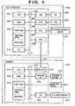
- FIG. 2 is a block diagram showing an example of a hardware configuration of an image processing system according to an embodiment of the present invention.
- the host computer 100 is comprised of a CPU 201 that executes multiple image processing based on an image processing program or the like stored on a program ROM in a ROM 203 or in an external memory 211.
- the CPU 201 comprehensively controls all the devices connected to a system bus 204.
- an operating system (OS) program and the like that is the control program for the CPU 201.
- OS operating system
- font ROM in the ROM 203 or in the external memory 211 is stored font data and the like used when performing the aforementioned image processing.
- On a data ROM in the ROM 203 or in the external memory 211 is stored a variety of data used when performing the aforementioned image processing and the like.
- a RAM 202 functions as the CPU 201 main memory, work area and so forth.
- a keyboard controller (KBC) 205 controls key input from a keyboard 209 and a pointing device, not shown.
- a CRT controller (CRTC) controls a CRT display (CRT) 210 display.
- a disk controller (DKC) 207 controls access to the external memory 211 such as a hard disk (HD) or a floppy disk (FD).
- HD hard disk
- FD floppy disk
- PRTC printer controller
- a printer controller (PRTC) 208 is connected to a printer 107 through an interactive interface (interface) and controls communication with the printer 107.
- the CPU 201 executes an outline font rasterize process to a display information RAM set on the RAM 202, for example, and enables WYSIWYG on the CRT 210.
- the CPU 201 opens a variety of windows registered on the basis of commands issued by a mouse cursor or the like, not shown, on the CRT 210, and executes a variety of data processes.
- the CPU 201 opens a window related to the print settings and enables the setting of a print process method for a printer driver, including selection of a print mode.
- the printer 107 is controlled by a CPU 312.
- a printer CPU 312 outputs an image signal as output information to a print unit (printer engine) 317 connected to a system bus 315 based on a control program or the like stored on a control program ROM or the like stored in a program ROM in the ROM 313 or in an external memory 314.
- a control program and the like for the CPU 312.
- font ROM in the ROM 313 is stored font data and the like used when generating the aforementioned output information.
- On the data ROM in the ROM 313 is stored information and the like used at the host computer 100 if the printer has no hard disk or other external memory 211.
- the CPU 312 enables communication with the host computer through an input unit 318, and can relay information and the like in the printer to the host computer 100.
- a RAM 319 is a RAM that functions as the main memory, work area and so forth of the CPU 312, and is constructed so as to be able to expand memory capacity using an option RAM connected to an expansion port, not shown. It should be noted that the RAM 319 is used as an output information raster area, an environmental data storage area, an NVRAM and the like. Access to the aforementioned hard disk, IC card or other external memory 314 is controlled by a memory controller (MC) 20.
- the external memory 314 is connected as an option, and stores font data, emulation programs, form data and the like.
- Reference numeral 321 designates a control panel, upon which are arranged switches, LEDs and the like for operating the system.
- the above-described external memory 211 is not limited to a single unit, and may instead constitute a plurality of units, and the system may be configured so as to be able to connect a plurality of external memories storing, in addition to internal fonts, programs that interpret printer control languages of different language systems and option cards.
- the external memory 211 may have an NVRAM, not shown, and store printer mode settings from the control panel 321.
- a network instead of a local connection may connect the host computer 100 and the printer 107.
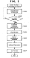
- FIG. 3 is a flow chart illustrating an operating procedure of an image processing apparatus in a case in which the image processing application shown in FIG. 1 is running.
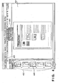
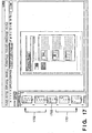
- FIG. 4 is a diagram showing one example of a user interface of the image processing application.
- the image processing application 101 uses a memory 202.
- Target page designation information 202a, selected page information 202b, target page information 202c, alignment position designation information 202d and retouch position and area information 202e are contained in the memory 202.
- the target page designation information 202a indicates whether (i) the image data file (page) that is the retouch application target is only the currently selected page, (ii) a page group consisting of every other page in accordance with the image data file (page) order, using the selected page as a reference, or (iii) all the pages contained in the target folder.
- Selected page information showing the one page currently selected is stored in the selected page information 202b.
- the selected page information 202b For example, all image data file names to which retouching is to be applied are contained therein.
- the target page information 202c may be eliminated because it can be determined uniquely from the target page designation information and the selected page information. Nevertheless, in the present embodiment, it is included in the interest of improving processing efficiency.
- the alignment position designation information 202d Information that is to serve as a reference for positionally aligning the page to be retouched is stored in the alignment position designation information 202d.
- information indication alignment positions such as upper left, lower left, upper right and lower right is included.
- the retouch position area information 202e is indicated by coordinates that use as a reference an origin (called a processing origin) that changes every time the alignment position designation information 202d changes. For example, if the alignment position is designated as upper left, then the retouch position is expressed by coordinate values that have as their processing origin the upper left corner of the image on the page that is currently selected.
- the retouch position is converted into coordinates based on the post-change processing origin. For example, even if the alignment position designation is changed from upper left to lower right, there is no change in the relative positions of the retouch position designated when the alignment position designation was the upper left and the position corresponding to the upper left corner of the selected page at the time that the upper left was designated as the alignment position.
- the image processing application 101 uses this type of storage area to carry out processing.
- other areas are also necessary, such as areas for rasterizing the image data files and areas for temporarily storing data during retouch, but since these are the same in an ordinary image processing application that does not have the functions of the present embodiment a description thereof is omitted here.
- image information on a plurality of images targeted for processing is acquired (S301).
- the processing targets may, for example, be image data files gathered into a specific folder and put in order. Of course, the processing targets may be designated by other methods.
- the size of the image data files is held as additional information.
- information on the size of the images in all of the image data files targeted for processing is acquired (S302).
- the magnification of the image display when displaying the thumbnail images is determined so that the image having the largest size among all the images for which size information is acquired becomes a thumbnail image of a previously determined fixed size and is stored in the memory (S303).
- Those images other than the largest image are also sized according to the magnification determined in step S303 and thumbnailed, and therefore, even as thumbnail images, the relative size ratios between images are kept at the same values as the original images.
- thumbnails are created in accordance with the determined magnification (thumbnail group 402 in FIG. 4 ) and displayed (S304).
- image data file designated when the image processing application 101 is started up that image data is displayed in order to allow an operator or the like to designate the content of the retouching (S305, image 401 in FIG. 4 ). If there is no file so designated, then the lead image data is displayed.
- the designated image data thumbnail is displayed so as to be distinguishable from the other thumbnails by color or the like (thumbnail 403 in FIG. 4 ).
- the retouch process is executed (S306) in response to the image editing work performed by the user, in particular the retouching of a plurality of images (S306).
- the retouched image data is then saved and the process terminates (S307).
- FIG. 4 is a diagram showing a sample of that which is displayed in steps S305 and S306, and is a user interface screen of the image processing application 101. Thumbnails 402, 403 and image 401 are displayed by the procedure described above. Besides this, a page forward button 405 and a target page switch drop-down menu 404 are also included in the display screen frame. The following is a detailed description of FIG. 3 , but it should be remembered that, in the following description, the image data is called a page.
- FIG. 5 is a flow chart illustrating details of an operating procedure of the image processing application 101 in the image editing process of step S306 shown in FIG. 3 .
- the editing of a plurality of images is implemented by a combination of the processes of designating the target page(s) to be edited (S501), changing the currently selected page (S502), designating the position and area of the retouch target in the selected page (S503), designating the image alignment position that designates the alignment position of each page (S504), retouching at the position and in the area designated for the targeted page(s) (S505), and updating the thumbnail displayed on the user interface (S506).
- step S501 to step S505 it is determined whether to execute or not in response to user choice, and therefore the step is not executed if there is no change in the item corresponding to that step.
- steps S501-S505 is executed in response to a user operation and the next input is awaited. Only the thumbnail update of step S506 is arranged in series, insofar as it is always executed immediately after one of the steps S501-S505 is executed.
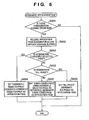
- FIG. 6 is a flow chart illustrating details of the target page designation process (S501) of the multiple image editing process.
- the image processing application 101 has for the user interface a user interface capable of switching the target page(s) (the target page switch drop-down menu 404 shown in FIG. 4 ). Through this interface, the user can switch the designation of the target page(s) at any time during the editing of an image by the image processing application 101.
- the area of possible choices for the target page switch includes the currently selected page (corresponding to the "displayed page" in the target page switch drop-down menu 404 shown in FIG.
- step S601 is not always necessary. However, step S601 is necessary where the processes are arranged in series as in FIG. 5 .
- the target page designation is temporarily deleted (S602). In other words, the target page information contained in the target page area 202c is cleared. Then, if the "currently selected page" is designated (S603), the currently selected page is designated the target page. At the same time, information identifying the currently selected page, for example, the file name of the image data file corresponding to the currently selected page, a pointer indicating same, or the like, is recorded in the target page area 202c. In that case, the image processing application 101 user interface enters the state shown in FIG. 4 . The currently selected page is displayed in the thumbnail 403 as the target page. The procedure for implementing the selected page and the target page thumbnail display will be described later with reference to FIG. 13 .
- all pages are designated as target pages.
- identifying information showing "all pages” is recorded in the target page designation area 202a.
- information identifying all pages for example, the file names of the image data files corresponding to all pages, pointers indicating same, or the like, is recorded in the target page area 202c.
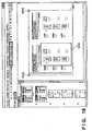
- the image processing application 101 user interface enters the state shown in FIG. 8 . All pages are displayed in the thumbnail in a way that makes it possible to identify the target pages (801, 802).
- every other page is designated the target page (S607).
- identifying information showing "every other page” is recorded in the target page designation area 202a.
- information identifying every other page using the currently selected page as a reference for example, the file names of the image data files corresponding to every other page, pointers indicating same, or the like, is recorded in the target page area 202c.
- the image processing application 101 user interface enters the state shown in FIG. 7 . Using the currently selected page as a reference, every other page is thumbnail-displayed as a target page (701, 702).
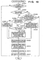
- FIG. 10 is a flow chart illustrating details pertaining to a selected page change process (S502) in the multiple image editing process.
- the user can designate the selected page from the image processing application 101 menu, and by designating a direct thumbnail image from the thumbnail display area 402, the selected page can be designated.
- the page forward button 404 shown in FIG. 9 on the image processing application 101 user interface the user does not directly designate the page but, using the currently selected page as a reference, can change each of the "first page (901)", “previous page (902)", “next page (903)” and "last page (904)” to the selected page. At this time, the change is of a selected page within the target page area.
- a configuration that provides a menu showing the same functions and implements the same functions when the user selects from the menu and presses a button is also possible.
- step S1001 is not always necessary. However, step S1001 is necessary if the processes are arranged in series as shown in FIG. 5 .
- step S1001 is necessary if the processes are arranged in series as shown in FIG. 5 .
- the operation is a page forward designation
- a page designatable by the page-forward designation is present in the current target page (S1003). This determination can be implemented, for example, by referring to the target page designation information 202a, the target page information 202c and the currently selected page information 202b.
- the target page becomes only the current page.
- the page-forward designation might designate, there is no page within the current target page indicated by the page-forward designation.
- the process terminates without changing the selected page.
- the target pages becomes all the pages.
- the currently selected page is neither the first page nor the last page, then for all page-forward designations a page exists within the currently selected pages that is indicated by the page-forward designation.
- that page is temporarily stored as the user-designated page (S1004) and later processes are carried out.
- a description will be given later of a later rendering process (S1009 and thereafter).
- the target pages becomes every other page and the image processing application 101 user interface enters the state shown in FIG. 17 .
- a thumbnail 1703 is the currently selected page. If in this state the user designates the "previous page” page-forward button (902) shown in FIG. 9 , as shown by arrow 1702, the page before the previous page is temporarily stored as the designated page (S1004). Similarly, if in this state the user designates the "next page” page-forward button (903) shown in FIG. 9 , as shown by arrow 1701, the page after the next page is temporarily stored as a designated page (S1004).
- the target page designation (S1005) is the "currently selected page". If the page-forward designation is the currently selected page, then the currently selected page is made the target page (S1005). In other words, the target page information 202c is changed to information pertaining to the designated page.
- the multiple image processing application enters the state shown in FIG. 4 .
- the currently selected page as the target page is displayed as a thumbnail (403). The procedure for implementing the thumbnail display of the selected page and the target page will be described later.
- the target page designation is "all pages" (Yes in S1007), the target page does not change even if the selected page changes, and therefore there is no change in the target page information.
- a description will be given of the rendering process of S1009 and thereafter, but when that process terminates, the multiple image processing application enters the state shown in FIG. 8 (801, 802).
- every other page including the designated page is made the target pages (S1008).
- the target page information 202c is updated with information pertaining to every other page including the designated page as a reference.
- the multiple image processing application user interface enters the state shown in FIG. 7 or FIG. 11 . For example, if the page 701 shown in FIG. 7 is selected, the image processing application enters the state shown in FIG. 7 . Using the currently selected page as a reference, every other page is thumbnail-displayed as a target page (701, 702).
- the image processing application 101 enters the state shown in FIG. 11 .
- every other page is thumbnail-displayed as a target page (1101, 1102).
- the page that the user designates is selected as the currently selected page (S1009).
- information for identifying the designated page is recorded as the selected page information 202b.
- the currently selected page is calculated (S1010).
- the origin of the current retouch position on the user interface screen is calculated (called the processing origin in FIG. 10 ), and the position of the currently selected page is calculated so that the alignment position of the currently selected page and the processing origin coincide.
- a coordinate system (called a retouch coordinate system) for the purpose of setting a retouch position and area.
- the origin of this coordinate system is the processing origin described above.
- the retouch position information 202e is shown as a coordinate in this retouch coordinate system.
- the selected page image size is xXy pixels and the page reference point is the upper left, then the position of that reference point in the retouch coordinate system is calculated. If the alignment position designation is "upper left", then, since the page reference point and the processing origin coincide, the coordinates of the page reference point in the retouch coordinate system are (0,0).
- the page reference position is converted into a coordinate system that has as its origin a position designated as an alignment position.
- the position of the currently selected page in the retouch coordinate system be calculated.
- the currently selected page is arranged and displayed on the user interface (in particular the area for displaying an image of the selected page), using as a reference the page reference position in the retouch coordinate system.
- the display necessitates converting the retouch coordinate system into a coordinate system on the user interface screen. This conversion may accompany sizing if the image display has been sized, or it may accompany translation to a display coordinate system.
- the size of the user interface screen may be determined by finding in advance the largest-sized page in the vertical and horizontal directions for all the pages to be processed and settling on the screen size that is displayable in both directions.
- the selected page may be reduction-displayed on the user interface provided that the reduced image is displayable.
- the processing origin on the user interface screen is switched so that the retouch position (so long as the retouch position designation is not changed) does not change on the user interface screen.
- the alignment position designation may be applied to the user interface screen, and if "upper left” is designated, moves the position of the processing origin toward the upper left of the user interface (in particular the area that displays an image of the selected page). If "lower right” is designated, then the processing origin is moved toward the lower right of the user interface (in particular the area that displays an image of the selected page). It is not necessary that the processing origin be placed precisely at the corner, and it is preferable that the processing origin be positioned slightly inside the corner in order to secure a margin.
- the display is such that the initially designated alignment position (that is, the original processing origin) is not moved in the coordinate system on the user interface.
- an object of a frame or the like showing the current retouch position and area is drawn having as its origin a position designated as the alignment position (S1012) and the selected page change process terminates.
- the position of the object of a frame or the like showing the current retouch position and area is determined based on the retouch position information 202e.
- the retouch position information 202e is given by the coordinates of the retouch coordinate system having the processing origin as its origin, and therefore there is no need for coordinate conversion other than that for display of the user interface.
- the position at which the current selected area is drawn before and after the selected page is changed does not move on the user interface but is drawn at the same position.
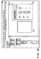
- FIGS. 18 , 19 and 20 show examples of renderings of a current selected area from a display of a currently selected page in a multiple image processing application.
- FIG. 18 if the size of the currently selected page (1801) is A3, a selected area designated as the retouch position (1802) is displayed. If, in this state, the user selects the page-forward button "next page" (903) shown in FIG. 9 and the size of the selected page is A4, and moreover if the alignment position designation is "upper left", then the selected page (1901) is displayed at the position shown in FIG. 19 .
- a selected area designated as the retouch position (1902) is displayed at the same position on the user interface of the multiple image processing application.
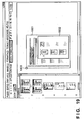
- FIG. 14 is a diagram showing one example of an image processing application 101 user interface display showing a retouch position created in the foregoing manner.
- the retouch position is displayed in a red frame (frame 1401 in the diagram), to distinguish it from the remaining areas.
- the retouch position and area is calculated and maintained using as a reference a position on the selected page image that is indicated by a designation value designated by a alignment position designation to be described later.
- a designation value designated by a alignment position designation to be described later.
- the retouch position is calculated based on the lower right corner 1402 of the selected page image, and in the case of 1401 the retouch is positioned in the negative direction along both the vertical and horizontal axes compared to the reference point 1402.
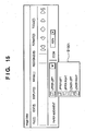
- FIG. 12 is a flow chart illustrating details of an alignment position (same as image alignment position) designation process (S504) during editing of a plurality of images (S306).
- a list 1501 of possible alignment position designations like that shown in FIG. 15 is displayed on the image processing application 101 user interface 401, and the user can change designations at any time.
- the alignment position designation where retouching a plurality of images at once, involves which coordinates of the image pages to apply the above-described retouch position, and is information that designates image page alignment positions.
- the retouch position on the selected page image is calculated using as a reference a position indicated by a designation value that designates an alignment position.
- FIGS. 16A, 16B a description will be given of retouching an A3-size image and an A5-size image in one operation, using the schematic diagrams of FIGS. 16A, 16B .
- area 1607 is designated as the retouch position. If "upper left” is designated by the alignment position designation and an image erase editing operation has been carried out, area 1607, which is the upper half of the A3 image 1601, becomes blank.
- the upper left 1603 corner of an A5 image 1602 is deemed disposed so as to overlap the upper left corner 1603 of the A3 image 1601 and an image erase editing operation is carried out at the position of the retouch position 1607. As a result, most of the page of the A5 image 1602 becomes blank.
- the alignment position designation is designated by the user and represents a change from the current alignment position designation (Yes in S1201), then for the currently selected page the difference between the new alignment position coordinates using the current alignment position as the origin (that is, the new alignment position coordinates having the current alignment position coordinates as its origin) is calculated (S1202).
- the coordinates of the process shown in FIG. 12 are coordinates in a case in which the image data targeted for processing is rendered as two-dimensional data, for example, values shown in pixel units.
- the right side and the bottom are assumed to be in the positive direction from the origin along their respective axes.
- the current alignment position is saved in the alignment position designation information 202d.
- the size of the currently selected page is 100 pixels horizontally and 200 pixels vertically. If “lower right” is selected as the alignment position designation and the user changes the alignment position designation to "upper left”, the new alignment position coordinates are (-100, -200), which is a subtraction of (100, 200) in each coordinate component from the coordinate origin (0,0).
- step S1202 the new alignment position coordinates calculated in step S1202 are subtracted from the retained retouch position coordinates (retouch position information 202e).
- the retouch position coordinates are (0,0)
- the (100,200) obtained by subtracting (-100,-200) from the (0,0) in each coordinate component becomes the new retouch position information. This value is saved as the retouch position information 202e.
- the value to be subtracted depends on the alignment position, and varies depending on the size of the selected image. Therefore, in the above-described example, the value (100,200) can be generalized, as, for example (x,y).
- step S1206 If there is such a necessity, then conversions for those coordinates are carried out in the same manner as step S1204.
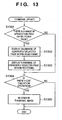
- FIG. 13 is a flow chart illustrating details pertaining to a thumbnail update operation (S506) during editing of a plurality of images. If there is a change in the target page or the selected page due to user designation (S1301), then thumbnails of all the current target pages are outlined in blue and displayed (S1302) and the thumbnail of the currently selected page is outlined in red and displayed (S1303).
- the current target page can be identified from the current target page information 202c.
- the currently selected page can be identified from the selected page information 202b. By this process, the currently selected page is always one of the target pages and is framed in red. In addition, the currently selected page is kept a single page. Multiple pages are never framed in red.
- This process is a step of simply inputting the retouch position information 202e.
- the retouch position and a retouch range of the area to be retouched are input by the user designating a desired area on a reduced image of the currently selected page displayed on a user interface screen like that shown in FIG. 4 using a pointing device or the like.
- the retouch position is expressed as coordinates having as their origin a position designated as the alignment position in the currently selected image.
- the retouch position is expressed as coordinates that take as their origin (the processing origin described above) the lower right corner of the selected image. That which is designated is on the user interface screen, and therefore the acquired retouch position is coordinates on the user interface, but the retouch position information 202e of a retouch coordinate system can be obtained by turning the inverse transformation obtained when reduction-displaying the selected page on the user interface screen into coordinates on the user interface. In step S2201 this value is saved.
- the retouch area may be expressed by the lengths in the X and Y directions using the retouch position as a reference, and these, too, are saved as retouch position information 202e (step S2202).
- the retouch position can be designating by designating an area formed by the right, left, top and bottom sides of an image and a distance from the reference sides.
- the retouch position can be designating by designating an area formed by the right, left, top and bottom sides of an image and a distance from the reference sides.
- the corners of a rectangle disposed opposite reference points and defined by distance and direction from the reference points can be designated and that rectangle designated as the retouch area.
- a menu or the like that displays input columns for input, for example, may be provided for the user interface for this purpose.
- a method such as that of scanning a document on which the retouch area is written in as frame lines and scanned from an image scanner or the like is conceivable.
- the frame lines showing the retouch area are translated so that the position on the scanned document image designated the alignment position becomes the processing origin in the retouch coordinate system, and appropriate positions of the translated frame lines are saved as retouch position information 202e.
- information for identifying the frame lines using the retouch position as a reference is made the retouch area and saved in the retouch position information 202e.
- step S505 shown in FIG. 5
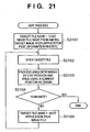
- FIG. 21 The processes shown in FIG. 21 are executed by designating from the user interface such items as, for example "execute image processing".
- the lead image data file in a file to be processed that is, information identifying the lead image data file in the target page information 202c, for example a file name
- a target file name area provided in the memory (S1201).
- the image data file of the file name saved in the target file name area is opened and rendered in the memory as image data (S1202).
- This image data is called target image data.
- separately designated image processing is carried out on an area identified by the position and area designated by the retouch position information 202e (called the retouch area), using as its origin a position designated the alignment position saved in the alignment position designation information 202d. In this instance, it is not always the case that the entire retouch area is in the target image data.
- An overlap area may be defined, for example, as an area of overlap in which an area of a retouch target exists within the respective X and Y dimensions of an area of target image data.
- the retouch area can be identified as follows. That is, assume that each piece of image data is defined by a coordinate system that takes as its origin the reference point therefor. Then, the retouch position in the retouch coordinate system is converted into a target image data coordinate system, and the retouch position thus obtained is retouched. In order to do so, the image data position (for example, the coordinates of the lower right corner of the image) corresponding to the alignment position designation (for example, "lower right") is expressed as coordinates (which is clear from the size of the image data) having as their origin the reference position of the target image (for example, the upper left corner), and the encoding of the values of the coordinate components of these coordinates is inverted.
- the image data position for example, the coordinates of the lower right corner of the image
- the alignment position designation for example, "lower right”
- the coordinates thus obtained are the coordinates of the reference position where the position on the target image corresponding to the alignment position designation is taken as the origin.
- the retouch position coordinates saved in the retouch position information 202e are given by the sum of the coordinates of the retouch position of the target image where the position on the target image corresponding to the alignment position designation is taken as the origin plus the coordinates of the retouch position having as its origin the reference position of the target image.
- the coordinates of the retouch position having the position on the target image corresponding to the alignment position designation as the origin can be obtained by subtracting the coordinates of the reference position of the target image taking as its origin the position on the target image corresponding to the alignment position designation from the coordinates of the retouch position taking as its origin the reference position of the target image.
- the area of the target image corresponding to this position is the target of the designated process, which is clear from vector addition and subtraction.
- image processing can be designated separately for each retouch position. Accordingly, where a plurality of retouch positions are designated, different types of image processing can be performed on the respective retouch positions. For example, a given area identified by a given retouch position and area can be whited out and noise reduction can be designated for a separate area.
- a given area identified by a given retouch position and area can be whited out and noise reduction can be designated for a separate area.
- the process terminates. If it is determined that processing of the target page is not finished, then information for identifying the next image data file from the target page information 202c is stored in the target file name area (S1205) and the process repeats from step S2102.
- the image-processed image data files are saved with the same name.
- the image processing system operates according to the procedure described above when the application 101 is run for multiple images.
- the retouched image data can then be printed using the printer 107 or the like shown in FIG. 2 .
- the retouched image data can be supplied to the document processing system 104 shown in FIG. 1 as input data to the document processing system 104.
- an image of the current page is displayed so that the designated image alignment position is disposed near a position corresponding to the image alignment position of the user interface screen of the image processing application 101.
- the designated image alignment position is disposed near a position corresponding to the image alignment position of the user interface screen of the image processing application 101.
- the reference position the image alignment position
- a margin is required on both sides thereof, and consequently, it is preferable that the reference position be disposed near the center of the user interface screen.
- FIG. 23 is a functional block diagram of an image processing apparatus that enables identical retouching of a plurality of retouch target images according to the present invention.
- the host computer 100 shown in FIG. 2 implements the functional blocks shown in FIG. 23 .
- the image data targeted for retouching is saved in an image data file 2304, and retouched image data also is returned to the image data file 2304.
- the user can designate a retouch position that is the target of retouching for a single image using a retouch position designating means 2301.
- the user can designate an image alignment position using an alignment position designating means 2302.
- designating means may be implemented, for example, by inputting retouch positions and alignment positions at a designation screen displayed by the user interface using the keyboard and pointing device shown in FIG. 2 .
- a retouching means 2303 aligns the retouch target image at the designated alignment position and retouches a designated area of the aforementioned single image using the designated retouch position as a reference. This operation is implemented by the CPU 201 executing the image processing application of the present embodiment. In particular, the procedure shown in FIG. 21 is the equivalent of the retouching means 2303.
- a display control means 2305 aligns and displays the retouch target image on the display screen at the alignment position as well as displays the designated area, which has as its reference the retouch position for the single image, so as to be identifiable.
- the display control means 2305 is implemented by the CPU 201 executing the image processing application of the present embodiment. In particular, the procedure shown in FIG. 13 is the equivalent of the display control means 2305.
- User interface screen like those shown in FIGS. 4 , 7 , 8 and 14-20 are displayed on a display unit 2306. In particular, as shown in FIG. 16B , images of different sizes are aligned using the alignment position as a reference and displayed by the display control means 2305.
- the retouch position for a document to be retouched can be confirmed while sequentially paging forward with the retouch position displayed as is.
- the retouch position for the document to be retouched can be confirmed easily while determining the display position of the image so that the retouch position is not changed on the display screen and sequentially paging forward looking only at the retouch position even if a paper alignment position is designated.
- the present invention can be applied to an apparatus comprising a single device or to a system constituted by a plurality of devices.
- the invention can be implemented by supplying a software program, which implements the functions of the foregoing embodiments, directly or indirectly to a system or apparatus, reading the supplied program with a computer of the system or apparatus, and then executing the program code.
- a software program which implements the functions of the foregoing embodiments
- reading the supplied program with a computer of the system or apparatus, and then executing the program code.
- the mode of implementation need not rely upon a program.
- the program code itself installed in the computer also implements the present invention.
- the claims of the present invention also cover a computer program for the purpose of implementing the functions of the present invention.
- the program may be executed in any form, e.g., as object code, a program executed by a interpreter, or scrip data supplied to an operating system.
- Examples of storage media that can be used for supplying the program are a floppy disk, a hard disk, an optical disk, a magneto-optical disk, a CD-ROM, a CD-R, a CD-RW, a magnetic tape, a non-volatile type memory card, a ROM, and a DVD (DVD-ROM and a DVD-R).
- a client computer can be connected to a website on the Internet using a browser of the client computer, and the computer program of the present invention or an automatically installable compressed file of the program can be downloaded to a recording medium such as a hard disk.
- the program of the present invention can be supplied by dividing the program code constituting the program into a plurality of files and downloading the files from different websites.
- a WWW (WorldWideWeb) server that downloads, to multiple users, the program files that implement the functions of the present invention by computer is also covered by the claims of the present invention.
- a storage medium such as a CD-ROM
- distribute the storage medium to users, allow users who meet certain requirements to download decryption key information from a website via the Internet, and allow these users to decrypt the encrypted program by using the key information, whereby the program is installed in the user computer.
- an operating system or the like running on the computer may perform all or a part of the actual processing so that the functions of the foregoing embodiments can be implemented by this processing.
- a CPU or the like mounted on the function expansion board or function expansion unit performs all or a part of the actual processing so that the functions of the foregoing embodiments can be implemented by this processing.
Landscapes
- Engineering & Computer Science (AREA)
- Multimedia (AREA)
- Signal Processing (AREA)
- Human Computer Interaction (AREA)
- Physics & Mathematics (AREA)
- Metallurgy (AREA)
- General Engineering & Computer Science (AREA)
- High Energy & Nuclear Physics (AREA)
- General Physics & Mathematics (AREA)
- Theoretical Computer Science (AREA)
- Ceramic Engineering (AREA)
- Processing Or Creating Images (AREA)
- Editing Of Facsimile Originals (AREA)
Applications Claiming Priority (2)
| Application Number | Priority Date | Filing Date | Title |
|---|---|---|---|
| JP2004122289A JP4332461B2 (ja) | 2004-04-16 | 2004-04-16 | 画像処理装置および方法 |
| JP2004122289 | 2004-04-16 |
Publications (2)
| Publication Number | Publication Date |
|---|---|
| EP1587033A1 EP1587033A1 (en) | 2005-10-19 |
| EP1587033B1 true EP1587033B1 (en) | 2008-07-16 |
Family
ID=34940801
Family Applications (1)
| Application Number | Title | Priority Date | Filing Date |
|---|---|---|---|
| EP05252300A Expired - Lifetime EP1587033B1 (en) | 2004-04-16 | 2005-04-13 | Batch editing of scanned images |
Country Status (7)
| Country | Link |
|---|---|
| US (1) | US7880919B2 (enExample) |
| EP (1) | EP1587033B1 (enExample) |
| JP (1) | JP4332461B2 (enExample) |
| KR (1) | KR100749586B1 (enExample) |
| CN (1) | CN100355582C (enExample) |
| DE (1) | DE602005008130D1 (enExample) |
| ES (1) | ES2306031T3 (enExample) |
Families Citing this family (14)
| Publication number | Priority date | Publication date | Assignee | Title |
|---|---|---|---|---|
| JP4826481B2 (ja) * | 2007-01-19 | 2011-11-30 | コニカミノルタビジネステクノロジーズ株式会社 | 画像処理装置及び画像形成装置 |
| USD591304S1 (en) * | 2007-02-27 | 2009-04-28 | Google Inc. | Graphical user interface for display screen of a communications terminal |
| JP5059545B2 (ja) * | 2007-10-23 | 2012-10-24 | 株式会社リコー | 画像処理装置及び画像処理方法 |
| JP2009258966A (ja) * | 2008-04-16 | 2009-11-05 | Canon Inc | 表示制御装置および表示制御方法 |
| US8171399B2 (en) * | 2008-07-17 | 2012-05-01 | International Business Machines Corporation | Using an alternate user interface to a drag and drop interface for rearranging configurable web page components |
| JP2010198203A (ja) * | 2009-02-24 | 2010-09-09 | Fuji Xerox Co Ltd | 情報処理装置及びプログラム |
| KR101613838B1 (ko) | 2009-05-19 | 2016-05-02 | 삼성전자주식회사 | 휴대 단말기의 홈 스크린 지원 방법 및 이를 지원하는 휴대 단말기 |
| JP5365537B2 (ja) * | 2010-02-02 | 2013-12-11 | 富士ゼロックス株式会社 | 情報処理装置及び情報処理プログラム |
| US20120060127A1 (en) * | 2010-09-06 | 2012-03-08 | Multitouch Oy | Automatic orientation of items on a touch screen display utilizing hand direction |
| CN103419513B (zh) * | 2012-05-15 | 2015-09-02 | 北大方正集团有限公司 | 一种随机图像的处理方法及一种印刷设备控制系统 |
| US9418460B2 (en) * | 2013-03-15 | 2016-08-16 | Lenovo (Singapore) Pte. Ltd. | Alignment based on visual content |
| JP5765364B2 (ja) * | 2013-04-17 | 2015-08-19 | コニカミノルタ株式会社 | 画像処理装置、プレビュー画像を表示する方法、およびプログラム |
| CN110059596B (zh) * | 2019-04-03 | 2020-07-07 | 北京字节跳动网络技术有限公司 | 一种图像识别方法、装置、介质和电子设备 |
| JP7214542B2 (ja) * | 2019-04-12 | 2023-01-30 | フォルシアクラリオン・エレクトロニクス株式会社 | 表示制御装置、及び表示制御方法 |
Family Cites Families (23)
| Publication number | Priority date | Publication date | Assignee | Title |
|---|---|---|---|---|
| JP3105895B2 (ja) * | 1989-04-12 | 2000-11-06 | キヤノン株式会社 | 文書処理装置 |
| US5235679A (en) * | 1989-06-14 | 1993-08-10 | Hitachi, Ltd. | Guidance method and apparatus upon a computer system |
| US5271065A (en) * | 1990-09-28 | 1993-12-14 | Xerox Corporation | Electronic printing system for printing signatures |
| JP2971688B2 (ja) | 1992-12-11 | 1999-11-08 | シャープ株式会社 | 複写機 |
| JP3808923B2 (ja) * | 1995-11-27 | 2006-08-16 | 株式会社東芝 | 情報処理装置 |
| US6000870A (en) * | 1996-10-14 | 1999-12-14 | Brother Kogyo Kabushiki Kaisha | Printing device having dual sheet feed trays |
| US5746528A (en) * | 1997-02-26 | 1998-05-05 | Hewlett-Packard Company | Hard copy apparatus with a print media telescoping tray system |
| JP3576819B2 (ja) | 1997-07-30 | 2004-10-13 | キヤノン株式会社 | 情報処理装置及び印刷制御方法並びに記憶媒体 |
| JP2000083161A (ja) | 1998-07-01 | 2000-03-21 | Canon Inc | 画像処理装置及びその方法、及び画像処理システム |
| JP3363793B2 (ja) | 1998-07-10 | 2003-01-08 | キヤノン株式会社 | 印刷制御方法及び装置 |
| JP2000224400A (ja) | 1999-01-29 | 2000-08-11 | Kyocera Mita Corp | 画像編集機能を有する画像形成装置 |
| JP2001197292A (ja) | 2000-01-17 | 2001-07-19 | Konica Corp | 画像形成装置 |
| JP2002136482A (ja) | 2000-11-02 | 2002-05-14 | Hitachi Medical Corp | 画像選択装置 |
| JP3878408B2 (ja) | 2000-11-16 | 2007-02-07 | 株式会社リコー | 画像処理装置、画像処理方法およびその方法をコンピュータに実行させるプログラムを記録したコンピュータ読み取り可能な記録媒体 |
| JP3733288B2 (ja) * | 2000-12-06 | 2006-01-11 | キヤノン株式会社 | 情報処理装置および印刷制御方法および記憶媒体 |
| JP2002205440A (ja) | 2001-01-10 | 2002-07-23 | Sharp Corp | 入力表示装置およびその制御方法 |
| US7177045B2 (en) * | 2001-04-13 | 2007-02-13 | Electronics For Imaging, Inc. | Process and system for mixed page imposition |
| JP3937965B2 (ja) | 2001-09-14 | 2007-06-27 | キヤノン株式会社 | 文書処理方法及びその装置とプログラム |
| US7188311B2 (en) | 2001-09-14 | 2007-03-06 | Canon Kabushiki Kaisha | Document processing method and apparatus, and print control method and apparatus |
| JP2003101748A (ja) | 2001-09-20 | 2003-04-04 | Ricoh Co Ltd | 画像形成装置 |
| KR20030093020A (ko) | 2002-06-01 | 2003-12-06 | 삼성전자주식회사 | 원고의 독취 화상 수정방법 및 장치 |
| JP2004080744A (ja) | 2002-06-17 | 2004-03-11 | Seiko Epson Corp | 印刷装置用の情報管理装置および情報管理方法並びにプログラム |
| JP4003550B2 (ja) | 2002-06-21 | 2007-11-07 | コニカミノルタホールディングス株式会社 | 画像形成装置 |
-
2004
- 2004-04-16 JP JP2004122289A patent/JP4332461B2/ja not_active Expired - Fee Related
-
2005
- 2005-04-13 DE DE602005008130T patent/DE602005008130D1/de not_active Expired - Lifetime
- 2005-04-13 ES ES05252300T patent/ES2306031T3/es not_active Expired - Lifetime
- 2005-04-13 EP EP05252300A patent/EP1587033B1/en not_active Expired - Lifetime
- 2005-04-14 US US11/105,547 patent/US7880919B2/en not_active Expired - Fee Related
- 2005-04-15 CN CNB2005100659151A patent/CN100355582C/zh not_active Expired - Fee Related
- 2005-04-15 KR KR1020050031338A patent/KR100749586B1/ko not_active Expired - Fee Related
Also Published As
| Publication number | Publication date |
|---|---|
| KR100749586B1 (ko) | 2007-08-14 |
| ES2306031T3 (es) | 2008-11-01 |
| US7880919B2 (en) | 2011-02-01 |
| CN100355582C (zh) | 2007-12-19 |
| CN1683163A (zh) | 2005-10-19 |
| EP1587033A1 (en) | 2005-10-19 |
| KR20060045746A (ko) | 2006-05-17 |
| JP2005311478A (ja) | 2005-11-04 |
| JP4332461B2 (ja) | 2009-09-16 |
| DE602005008130D1 (de) | 2008-08-28 |
| US20050237573A1 (en) | 2005-10-27 |
Similar Documents
| Publication | Publication Date | Title |
|---|---|---|
| US10289350B2 (en) | Information processing device, printing condition setting method, and computer product | |
| US7426057B2 (en) | Document processing method | |
| US8218190B2 (en) | Document processing apparatus and method | |
| US8689100B2 (en) | Document processing apparatus, control method therefor, and computer program | |
| US8351067B2 (en) | Device to edit documents for printout and method thereof | |
| EP2237167A2 (en) | Information processing apparatus and method, and print control program | |
| JP4095458B2 (ja) | 文書管理装置、文書管理装置の制御方法、記憶媒体、プログラム | |
| EP1587033B1 (en) | Batch editing of scanned images | |
| JP4921335B2 (ja) | ドキュメント処理装置及び検索方法 | |
| US6621993B2 (en) | Image processing apparatus, image-forming apparatus, image forming system, and image-job linking method | |
| JP4101052B2 (ja) | 文書管理装置、文書管理装置の制御方法、及び、コンピュータプログラム | |
| JP7154982B2 (ja) | 情報処理装置、制御方法、及びプログラム | |
| US8643880B2 (en) | Control apparatus and control program controlling printing plurality of image files | |
| JP2009140311A (ja) | 文書処理装置および文書処理方法 | |
| CN113378610A (zh) | 信息处理装置以及计算机可读介质 | |
| JPH11232001A (ja) | プリンタ制御装置 | |
| JP2007124617A (ja) | 画像合成装置および画像合成装置の制御方法 | |
| JP4756149B2 (ja) | フォトアルバム作成システム及びフォトアルバム作成コンピュータプログラム | |
| JP2005182476A (ja) | ファイリングシステムおよびファイリング方法およびプログラムおよび記録媒体 | |
| JP2021081792A (ja) | 情報処理装置、情報処理方法、及びプログラム | |
| JP2018093411A (ja) | 情報処理装置、その制御方法とプログラム |
Legal Events
| Date | Code | Title | Description |
|---|---|---|---|
| PUAI | Public reference made under article 153(3) epc to a published international application that has entered the european phase |
Free format text: ORIGINAL CODE: 0009012 |
|
| AK | Designated contracting states |
Kind code of ref document: A1 Designated state(s): AT BE BG CH CY CZ DE DK EE ES FI FR GB GR HU IE IS IT LI LT LU MC NL PL PT RO SE SI SK TR |
|
| AX | Request for extension of the european patent |
Extension state: AL BA HR LV MK YU |
|
| 17P | Request for examination filed |
Effective date: 20060419 |
|
| AKX | Designation fees paid |
Designated state(s): DE ES FR GB IT NL |
|
| GRAP | Despatch of communication of intention to grant a patent |
Free format text: ORIGINAL CODE: EPIDOSNIGR1 |
|
| GRAS | Grant fee paid |
Free format text: ORIGINAL CODE: EPIDOSNIGR3 |
|
| GRAA | (expected) grant |
Free format text: ORIGINAL CODE: 0009210 |
|
| AK | Designated contracting states |
Kind code of ref document: B1 Designated state(s): DE ES FR GB IT NL |
|
| REG | Reference to a national code |
Ref country code: GB Ref legal event code: FG4D |
|
| REF | Corresponds to: |
Ref document number: 602005008130 Country of ref document: DE Date of ref document: 20080828 Kind code of ref document: P |
|
| REG | Reference to a national code |
Ref country code: ES Ref legal event code: FG2A Ref document number: 2306031 Country of ref document: ES Kind code of ref document: T3 |
|
| PLBE | No opposition filed within time limit |
Free format text: ORIGINAL CODE: 0009261 |
|
| STAA | Information on the status of an ep patent application or granted ep patent |
Free format text: STATUS: NO OPPOSITION FILED WITHIN TIME LIMIT |
|
| 26N | No opposition filed |
Effective date: 20090417 |
|
| PGFP | Annual fee paid to national office [announced via postgrant information from national office to epo] |
Ref country code: NL Payment date: 20140415 Year of fee payment: 10 Ref country code: IT Payment date: 20140402 Year of fee payment: 10 Ref country code: ES Payment date: 20140409 Year of fee payment: 10 |
|
| REG | Reference to a national code |
Ref country code: NL Ref legal event code: MM Effective date: 20150501 |
|
| PG25 | Lapsed in a contracting state [announced via postgrant information from national office to epo] |
Ref country code: IT Free format text: LAPSE BECAUSE OF NON-PAYMENT OF DUE FEES Effective date: 20150413 |
|
| PG25 | Lapsed in a contracting state [announced via postgrant information from national office to epo] |
Ref country code: NL Free format text: LAPSE BECAUSE OF NON-PAYMENT OF DUE FEES Effective date: 20150501 |
|
| REG | Reference to a national code |
Ref country code: FR Ref legal event code: PLFP Year of fee payment: 12 |
|
| REG | Reference to a national code |
Ref country code: ES Ref legal event code: FD2A Effective date: 20160527 |
|
| PG25 | Lapsed in a contracting state [announced via postgrant information from national office to epo] |
Ref country code: ES Free format text: LAPSE BECAUSE OF NON-PAYMENT OF DUE FEES Effective date: 20150414 |
|
| REG | Reference to a national code |
Ref country code: FR Ref legal event code: PLFP Year of fee payment: 13 |
|
| REG | Reference to a national code |
Ref country code: FR Ref legal event code: PLFP Year of fee payment: 14 |
|
| PGFP | Annual fee paid to national office [announced via postgrant information from national office to epo] |
Ref country code: FR Payment date: 20200429 Year of fee payment: 16 |
|
| PGFP | Annual fee paid to national office [announced via postgrant information from national office to epo] |
Ref country code: GB Payment date: 20200429 Year of fee payment: 16 |
|
| PGFP | Annual fee paid to national office [announced via postgrant information from national office to epo] |
Ref country code: DE Payment date: 20200629 Year of fee payment: 16 |
|
| REG | Reference to a national code |
Ref country code: DE Ref legal event code: R119 Ref document number: 602005008130 Country of ref document: DE |
|
| GBPC | Gb: european patent ceased through non-payment of renewal fee |
Effective date: 20210413 |
|
| PG25 | Lapsed in a contracting state [announced via postgrant information from national office to epo] |
Ref country code: FR Free format text: LAPSE BECAUSE OF NON-PAYMENT OF DUE FEES Effective date: 20210430 Ref country code: GB Free format text: LAPSE BECAUSE OF NON-PAYMENT OF DUE FEES Effective date: 20210413 Ref country code: DE Free format text: LAPSE BECAUSE OF NON-PAYMENT OF DUE FEES Effective date: 20211103 |