EP1586814B1 - Leuchtenfeld - Google Patents
Leuchtenfeld Download PDFInfo
- Publication number
- EP1586814B1 EP1586814B1 EP05008107A EP05008107A EP1586814B1 EP 1586814 B1 EP1586814 B1 EP 1586814B1 EP 05008107 A EP05008107 A EP 05008107A EP 05008107 A EP05008107 A EP 05008107A EP 1586814 B1 EP1586814 B1 EP 1586814B1
- Authority
- EP
- European Patent Office
- Prior art keywords
- grid
- emitting diodes
- reflector
- light
- lighting system
- Prior art date
- Legal status (The legal status is an assumption and is not a legal conclusion. Google has not performed a legal analysis and makes no representation as to the accuracy of the status listed.)
- Expired - Lifetime
Links
Images


Classifications
-
- F—MECHANICAL ENGINEERING; LIGHTING; HEATING; WEAPONS; BLASTING
- F21—LIGHTING
- F21S—NON-PORTABLE LIGHTING DEVICES; SYSTEMS THEREOF; VEHICLE LIGHTING DEVICES SPECIALLY ADAPTED FOR VEHICLE EXTERIORS
- F21S8/00—Lighting devices intended for fixed installation
- F21S8/02—Lighting devices intended for fixed installation of recess-mounted type, e.g. downlighters
- F21S8/026—Lighting devices intended for fixed installation of recess-mounted type, e.g. downlighters intended to be recessed in a ceiling or like overhead structure, e.g. suspended ceiling
-
- F—MECHANICAL ENGINEERING; LIGHTING; HEATING; WEAPONS; BLASTING
- F21—LIGHTING
- F21V—FUNCTIONAL FEATURES OR DETAILS OF LIGHTING DEVICES OR SYSTEMS THEREOF; STRUCTURAL COMBINATIONS OF LIGHTING DEVICES WITH OTHER ARTICLES, NOT OTHERWISE PROVIDED FOR
- F21V11/00—Screens not covered by groups F21V1/00, F21V3/00, F21V7/00 or F21V9/00
- F21V11/06—Screens not covered by groups F21V1/00, F21V3/00, F21V7/00 or F21V9/00 using crossed laminae or strips, e.g. grid-shaped louvers; using lattices or honeycombs
-
- F—MECHANICAL ENGINEERING; LIGHTING; HEATING; WEAPONS; BLASTING
- F21—LIGHTING
- F21V—FUNCTIONAL FEATURES OR DETAILS OF LIGHTING DEVICES OR SYSTEMS THEREOF; STRUCTURAL COMBINATIONS OF LIGHTING DEVICES WITH OTHER ARTICLES, NOT OTHERWISE PROVIDED FOR
- F21V7/00—Reflectors for light sources
- F21V7/0083—Array of reflectors for a cluster of light sources, e.g. arrangement of multiple light sources in one plane
-
- F—MECHANICAL ENGINEERING; LIGHTING; HEATING; WEAPONS; BLASTING
- F21—LIGHTING
- F21V—FUNCTIONAL FEATURES OR DETAILS OF LIGHTING DEVICES OR SYSTEMS THEREOF; STRUCTURAL COMBINATIONS OF LIGHTING DEVICES WITH OTHER ARTICLES, NOT OTHERWISE PROVIDED FOR
- F21V21/00—Supporting, suspending, or attaching arrangements for lighting devices; Hand grips
- F21V21/02—Wall, ceiling, or floor bases; Fixing pendants or arms to the bases
- F21V21/04—Recessed bases
-
- F—MECHANICAL ENGINEERING; LIGHTING; HEATING; WEAPONS; BLASTING
- F21—LIGHTING
- F21V—FUNCTIONAL FEATURES OR DETAILS OF LIGHTING DEVICES OR SYSTEMS THEREOF; STRUCTURAL COMBINATIONS OF LIGHTING DEVICES WITH OTHER ARTICLES, NOT OTHERWISE PROVIDED FOR
- F21V29/00—Protecting lighting devices from thermal damage; Cooling or heating arrangements specially adapted for lighting devices or systems
- F21V29/50—Cooling arrangements
- F21V29/70—Cooling arrangements characterised by passive heat-dissipating elements, e.g. heat-sinks
- F21V29/74—Cooling arrangements characterised by passive heat-dissipating elements, e.g. heat-sinks with fins or blades
- F21V29/76—Cooling arrangements characterised by passive heat-dissipating elements, e.g. heat-sinks with fins or blades with essentially identical parallel planar fins or blades, e.g. with comb-like cross-section
- F21V29/763—Cooling arrangements characterised by passive heat-dissipating elements, e.g. heat-sinks with fins or blades with essentially identical parallel planar fins or blades, e.g. with comb-like cross-section the planes containing the fins or blades having the direction of the light emitting axis
-
- F—MECHANICAL ENGINEERING; LIGHTING; HEATING; WEAPONS; BLASTING
- F21—LIGHTING
- F21Y—INDEXING SCHEME ASSOCIATED WITH SUBCLASSES F21K, F21L, F21S and F21V, RELATING TO THE FORM OR THE KIND OF THE LIGHT SOURCES OR OF THE COLOUR OF THE LIGHT EMITTED
- F21Y2105/00—Planar light sources
- F21Y2105/10—Planar light sources comprising a two-dimensional [2D] array of point-like light-generating elements
-
- F—MECHANICAL ENGINEERING; LIGHTING; HEATING; WEAPONS; BLASTING
- F21—LIGHTING
- F21Y—INDEXING SCHEME ASSOCIATED WITH SUBCLASSES F21K, F21L, F21S and F21V, RELATING TO THE FORM OR THE KIND OF THE LIGHT SOURCES OR OF THE COLOUR OF THE LIGHT EMITTED
- F21Y2115/00—Light-generating elements of semiconductor light sources
- F21Y2115/10—Light-emitting diodes [LED]
Definitions
- the invention relates to a luminaire field, in particular for the interior lighting, with a plurality of spaced light emitting diodes, a support member on which the light emitting diodes are arranged and arranged in the emission direction in front of the light emitting diode reflector body having a plurality of interconnected individual reflectors for the light emitting diodes ,
- Such a luminous field is for example from the DE 201 16 022 known.
- the disclosed in this document luminous field for the illumination of rooms consists of a plurality of light-emitting diodes, which are arranged on a support member formed as a carrier element, and a reflector body, which is arranged in the emission direction in front of the carrier board and the light-emitting diodes to the emitted light from the LEDs to bundle.
- the Indian DE 201 16 022 disclosed reflector body consists of a one-piece injection molded part with a plurality of channel-like individual reflectors. These individual reflectors are preferably vapor-deposited with aluminum in order to achieve a corresponding degree of reflection.
- transparent, light-bundling optics made of plastic are known, which are used in conjunction with known light fields as a reflector body.
- Known reflector body are formed as plastic elements, which have a low temperature resistance and also have a high insulation effect. This insulating effect can lead to a heat accumulation and thus defects in LEDs with a larger power.
- Light panels known which consist of several grid-like arranged on a support element LEDs.
- the LEDs of these light panels have for a uniform and sufficient interior lighting to low power.
- the individual LEDs would have to be arranged so close to the light panels that not every LED could be equipped with a single reflector.
- US 6106137 discloses a reflector for automotive lighting, for example of anodized aluminum, which consists of two disks, each comprising a plurality of holes and associated therewith integrally formed mini reflector portions forming mini-reflectors in the juxtaposition of the discs.
- the invention has for its object to further develop a generic luminaire field such that it can be used with light emitting diodes with a larger wattage.
- the grid according to the invention has the function of uniformly distributing the light emitted by the light-emitting diodes over a certain area and making a glare limitation. Due to the heat resistance and the heat-conducting properties of. Metal sheet grid LEDs with correspondingly high wattage can be used easily.
- the continuous air convection cools the light-emitting diodes in order to avoid heat build-up.
- This embodiment is preferably realized in light emitting diodes with a particularly high power.
- the thermal conductivity of the metal sheet grid is also sufficient to dissipate the heat generated when lenses or glass plates are arranged on the grid in front of the light-emitting diodes.
- the metal sheet of the grid is highly reflective and the grid is formed in such a multi-piece, that each individual reflector comprises parts of the reflector body and each fixed to this individual separate Operaflektor vom.
- the highly reflective property can be achieved, for example, by using anodized, anodized and correspondingly coated metal sheets.
- pre-anodized aluminum is used, which is highly reflective and has a reflectance of 95 percent. Since such pre-anodized and coated metal sheets have a very hard, almost ceramic surface, they can only be machined to a limited extent without damaging the reflection properties of the surface. Thus, these materials are only limited thermoformable, without causing micro-cracks in the surface and thus the destruction of the photometric properties. For this reason, when using pre-anodized metal sheets, the grid is constructed in several parts in order to avoid such damage to the reflecting surface. For example, you can the individual reflector surfaces consist of several individual plates, which are connected by tabs.
- any geometry of the individual reflector surfaces can thus also be realized with pre-anodized metal sheets without damaging the reflection surfaces.
- the individual reflector surfaces are formed as truncated pyramids, for example, two opposite reflector surfaces may be integrally formed on the grid and the adjacent, also opposite reflector surfaces are attached as separate parts of these tabs.
- a part of a grid fastener is integrally formed on the grid in order to connect this easily with a lamp housing.
- This part of the grid closure may comprise, for example, as an integrally formed locking tab with a latching hook. In an alternative embodiment, this tab may have an undercut.
- the support element of the luminous field is designed as a heat sink.
- the light-emitting diodes are thus arranged grid-like on the serving as a heat sink support member and can be arranged together with this in known light housings.
- the inventive design thus makes it possible for the first time to order luminaire fields with LEDs high wattage subsequently in existing luminaire housings, so to retrofit them.
- the heat sink thereby effectively dissipates the heat generated at the individual light-emitting diodes.
- the luminaire field according to the invention consists essentially of a square frame 10 which can be inserted into a suspended ceiling, in the opening of which a square metal sheet grid 20 is likewise inserted, and a heat sink 40 fastened to the frame 10, on the underside of which several light-emitting diodes 50 are arranged in a grid-like manner.
- a bridge-like mounting bracket 30 is provided for attachment to the ceiling in a known manner.
- the grid according to the invention has a total of 16 grid-like arranged individual reflectors 22, each having the geometry of a truncated pyramid.
- the grid 20 consists of a sheet metal profile of pre-anodized aluminum with a square base.
- truncated pyramidal reflector surfaces 24 are punched out of the sheet metal profile and bent out of the plane of the grid 20 upwards.
- the reflector surfaces 24 have at the oblique outer edges at a distance from each other in each case two fastening tabs 26.
- pyramid-truncated partial reflectors 28 are placed to form the complete individual reflectors 22, which have corresponding openings for these fastening tabs 26.
- the fastening tabs 26 By bending the fastening tabs 26, the separate partial reflectors 28 are fixed to the grid 20 to form the individual reflectors 22.
- This "multi-piece" structure of the grid 20 allows the use of pre-anodized metal sheets to form any geometry of the individual reflectors, without the reflective surface is damaged during deep drawing or the like.
- the heat sink 40 is provided on its upper side with a plurality of parallel cooling fins 42 and provided on its underside with a planar mounting surface 44.
- each individual reflector 22 is associated with a corresponding light-emitting diode 50.
- a plurality of light-emitting diodes may also be arranged on a substrate connecting them, which is then fastened to the mounting surface 44 of the heat sink.
- L-shaped grid plate 60 are formed on the outside in the installed position partial reflectors 28.
- These grid tabs consist of a first vertically extending from the upper end of the subreflector 28 section, which then merges after a 90 degree bend in an outwardly projecting horizontal section 62 and then after a further 90 degrees bend upwards in a longer, second vertical section 64 passes, which has a latching projection 66 at its upper end.
- This resilient grid plate 60 engages in the installed position a correspondingly formed detent tab 80 with a latching projection 82 to fix the grid 20 on the frame 10 and on the heat sink 40.
- the invention is not limited to truncated pyramid-shaped individual reflectors, but is equally applicable to single reflectors with different geometry.
- an inventively designed luminous field can be realize the lighting of a room with 100 - 300 LUX luminosity.
- other grid divisions than the mentioned 4 ⁇ 4 screening can also be realized.
- Due to the inventive design of a sheet metal grid with serving as a carrier for the light emitting heatsink also existing lights can be converted with conventional bulbs on the operation with light emitting diodes. For this purpose, only the existing of the reflector, the heat sink and the LEDs unit must be used in a lamp.
- the metal sheet grid according to the invention is characterized in comparison to the plastic grids by a high heat resistance and good heat dissipation and thus supports the heat dissipation even at extreme temperature development of light emitting diodes with high performance.
- the partial reflectors of the grid shield the diodes on the one hand and, on the other hand, focus the light due to the high reflection effect of the material used.
Landscapes
- Engineering & Computer Science (AREA)
- General Engineering & Computer Science (AREA)
- Non-Portable Lighting Devices Or Systems Thereof (AREA)
- Arrangement Of Elements, Cooling, Sealing, Or The Like Of Lighting Devices (AREA)
- Optical Elements Other Than Lenses (AREA)
- Medicines Containing Material From Animals Or Micro-Organisms (AREA)
- Fats And Perfumes (AREA)
- Detergent Compositions (AREA)
Description
- Die Erfindung betrifft ein Leuchtenfeld, insbesondere für die Innenraumbeleuchtung, mit einer Mehrzahl von in einem Abstand zueinander angeordneten Leuchtdioden, einem Tragelement, auf dem die Leuchtdioden angeordnet sind und einem in Abstrahlrichtung vor den Leuchtdioden angeordneten Reflektorkörper, der mehrere miteinander verbundene Einzelreflektoren für die Leuchtdioden aufweist.
- Ein derartiges Leuchtenfeld ist beispielsweise aus der
DE 201 16 022 bekannt. Das in dieser Druckschrift offenbarte Leuchtenfeld zur Beleuchtung von Räumen besteht aus einer Vielzahl von Leuchtdioden, die auf einer als Trägerplatine ausgebildeten Tragelement angeordnet sind, und einem Reflektorkörper, der in Abstrahlrichtung vor der Trägerplatine und den Leuchtdioden angeordnet ist, um das von den Leuchtdioden emittierte Licht zu bündeln. Der in derDE 201 16 022 offenbarte Reflektorkörper besteht aus einem einstückigen Spritzgussteil mit mehreren kanalartigen Einzelreflektoren. Diese Einzelreflektoren sind vorzugsweise mit Aluminium bedampft, um einen entsprechenden Reflektionsgrad zu erzielen. Daneben sind transparente, lichtbündelnde Optiken aus Kunststoff bekannt, die in Verbindung mit bekannten Leuchtenfeldern als Reflektorkörper eingesetzt werden. - Bekannte Reflektorkörper sind als Kunststoffelemente ausgebildet, die eine geringe Temperaturbeständigkeit aufweisen und zudem eine hohe Isolationswirkung haben. Diese Isolationswirkung kann bei Leuchtdioden mit einer größeren Leistung zu einem Wärmestau und mithin zu Defekten führen.
- Ferner sind aus der
WO 99/41 785 - Die jüngste Entwicklung hat Leuchtdioden mit einer größeren Leistung von 3-5 Watt mit einer wesentlich höheren Lichtausbeute hervorgebracht. Diese Leuchtdioden erzeugen jedoch gleichzeitig eine erheblich höhere Wärmeleistung. Grundsätzlich ist es wünschenswert, herkömmliche Leuchtmittel wie Leuchtstoffröhren, durch diese Leuchtdioden mit größerer Wattage zu ersetzen, da diese wesentlich effizienter als herkömmliche Leuchtmittel sind und eine deutlich größere Lebensdauer aufweisen.
-
US 6106137 offenbart einen Reflektor für eine Kraftfahrzeugbeleuchtung, beispielsweise aus eloxiertem Aluminium, der aus zwei Scheiben besteht, die jeweils mehrere Löcher und diesen zugeordnete angeformte Minireflektorabschnitte umfassen, die beim Aufeinanderlegen der Scheiben Minireflektoren bilden. - Der Erfindung liegt die Aufgabe zugrunde, ein gattungsgemäßes Leuchtenfeld derart weiterzuentwickeln, dass dieses auch mit Leuchtdioden mit einer größeren Wattage verwendbar ist.
- Diese Aufgabe wird bei einem Leuchtenfeld der eingangs genannten Art dadurch gelöst, dass der Reflektorkörper als ein aus Metallblech bestehendes Raster ausgebildet ist. Das erfindungsgemäße Raster hat die Funktion, das von den Leuchtdioden flächig emittierte Licht auf einer bestimmten Fläche gleichmäßig zu verteilen und eine Blendungsbegrenzung vorzunehmen. Aufgrund der Wärmbeständigkeit und der wärmeleitenden Eigenschaften des. Metallblechrasters können Leuchtdioden mit entsprechend hoher Wattage problemlos eingesetzt werden.
- Wenn das erfindungsgemäße Raster offen ausgebildet ist, also in Abstrahlrichtung vor den Leuchtdioden keine Abschirmung oder Platte angeordnet ist, kühlt die kontinuierliche Luftkonvektion die Leuchtdioden zur Vermeidung eines Wärmestaus. Diese Ausführungsform wird vorzugsweise bei Leuchtdioden mit einer besonders hohen Leistung verwirklicht. Die Wärmeleitfähigkeit des Metallblechrasters ist aber auch ausreichend, um die entstehende Wärme abzuführen, wenn an dem Raster vor den Leuchtdioden Linsen oder Glasplatten angeordnet sind.
- Das Metallblech des Rasters ist hoch reflektierend und das Raster ist derart mehrstückig ausgebildet, dass jeder Einzelreflektor Teile des Reflektorkörpers und jeweils an diesem fixierte einzelne getrennte Teilreflektorflächen umfasst. Die hoch reflektierende Eigenschaft lässt sich z.B. durch Verwendung von voreloxierten, eloxierten und entsprechend beschichteten Metallblechen erzielen. Vorzugsweise wird voreloxiertes Aluminium eingesetzt, das hoch reflektierend ist und einen Reflektionsgrad von 95 Prozent aufweist. Da derartige voreloxierte und beschichtete Metallbleche eine sehr harte, fast keramische Oberfläche aufweisen, können diese nur beschränkt mechanisch bearbeitet werden, ohne die Reflektionseigenschaften der Oberfläche zu beschädigen. So sind diese Materialien nur begrenzt tiefziehbar, ohne dass es zu Mikrorissen in der Oberfläche und damit zur Zerstörung der lichttechnischen Eigenschaften kommt. Aus diesem Grund ist das Raster bei der Verwendung von voreloxierten Metallblechen mehrstückig aufgebaut, um derartige Beschädigungen der reflektierenden Oberfläche zu vermeiden. Beispielsweise können die Einzelreflektorflächen aus mehreren Einzelplatten bestehen, die durch Laschen miteinander verbunden sind.
- Durch die erfindungsgemäße mehrteilige Ausführung des Reflektors lässt sich somit auch mit voreloxierten Metallblechen jede beliebige Geometrie der Einzelreflektorflächen ohne Beschädigung der Reflektionsflächen realisieren.
- Wenn die Einzelreflektorflächen als Pyramidenstümpfe ausgebildet sind, können beispielsweise jeweils zwei gegenüberliegende Reflektorflächen einstückig an dem Raster ausgebildet sein und die angrenzenden, sich ebenfalls gegenüberliegenden Reflektorflächen sind als getrennte Teile an diesen Laschen befestigt.
- In einer Weiterentwicklung kann vorgesehen sein, dass an dem Raster ein Teil eines Rasterverschlusses einstückig angeformt ist, um dieses einfach mit einem Leuchtengehäuse verbinden zu können. Dieses Teil des Rasterverschlusses kann beispielsweise als eine einstückig angeformte Rastlasche mit einem Rasthaken umfassen. In einer alternativen Ausbildung kann diese Lasche einen Hinterschnitt aufweisen.
- Vorteilhafterweise ist das Tragelement des Leuchtenfeldes als Kühlkörper ausgebildet. Die Leuchtdioden sind mithin rasterartig auf dem als Kühlkörper dienenden Tragelement angeordnet und können zusammen mit diesem in bekannten Leuchtengehäusen angeordnet werden. Die erfindungsgemäße Ausbildung ermöglicht es damit erstmalig, Leuchtenfelder mit Leuchtdioden hoher Wattage nachträglich in bestehenden Leuchtengehäusen anzuordnen, diese also umzurüsten. Der Kühlkörper führt dabei die an den einzelnen Leuchtdioden entstehende Wärme wirksam ab.
- Die Erfindung wird nachfolgend anhand einer bevorzugten Ausführungsform beschrieben, wobei auf die beigefügten Zeichnungen Bezug genommen wird. In diesen zeigen:
- Fig. 1
- eine perspektivische Ansicht eines erfindungsgemäßen Leuchtenfeldes;
- Fig. 2
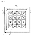
- eine Ansicht von unten des Leuchtenfeldes gemäß
Figur 1 ; - Fig. 3
- eine Ansicht des erfindungsgemäßen Rasters; und
- Fig. 4
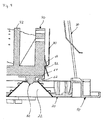
- einen vergrößerten Ausschnitt entlang der Linie IV-IV gemäß
Figur 2 . - Demnach besteht das erfindungsgemäße Leuchtenfeld im Wesentlichen aus einem in eine abgehängte Decke einlassbaren, quadratischen Rahmen 10, in dessen Öffnung ein ebenfalls quadratisches Metallblechraster 20 eingesetzt ist, und einem an dem Rahmen 10 befestigten Kühlkörper 40, an dessen Unterseite mehrere Leuchtdioden 50 rasterartig angeordnet sind. An der Oberseite des Rahmens 10 ist in bekannter Weise ein brückenartiger Montagebügel 30 zur Befestigung an der Decke vorgesehen.
- Das erfindungsgemäße Raster weist insgesamt 16 rasterartig angeordnete Einzelreflektoren 22 auf, die jeweils die Geometrie eines Pyramidenstumpfes aufweisen. Wie insbesondere aus der
Figur 3 zu entnehmen ist, besteht das Raster 20 aus einem Metallblechprofil aus voreloxiertem Aluminium mit quadratischer Grundfläche. - Zur Ausbildung der Einzelreflektoren 22 sind aus dem Metallblechprofil pyramidenstumpfförmige Reflektorflächen 24 ausgestanzt und aus der Ebene des Rasters 20 nach oben gebogen. Die Reflektorflächen 24 weisen an den schräg verlaufenden Außenkanten im Abstand zueinander jeweils zwei Befestigungslaschen 26 auf. Auf diese Befestigungslaschen 26 werden zur Bildung der vollständigen Einzelreflektoren 22 ebenfalls pyramidenstumpfförmige Teilreflektoren 28 aufgesetzt, die entsprechende Öffnungen für diese Befestigungslaschen 26 aufweisen. Durch umbiegen der Befestigungslaschen 26 werden die getrennten Teilreflektoren 28 an dem Raster 20 zur Bildung der Einzelreflektoren 22 fixiert. Dieser "mehrstückige" Aufbau des Rasters 20 ermöglicht den Einsatz von voreloxierten Metallblechen zur Ausbildung beliebiger Geometrien der Einzelreflektoren, ohne dass die reflektierende Oberfläche beim Tiefziehen oder dergleichen beschädigt wird.
- Der Kühlkörper 40 ist an seiner Oberseite mit mehreren parallel verlaufenden Kühlrippen 42 versehen und an seiner Unterseite mit einer planen Montagefläche 44 versehen. Auf dieser Montagefläche 44 sind entsprechend der Einzelreflektoren 22 des Rasters 20 Leuchtdioden 50 mit hoher Wattage so im Abstand zueinander angeordnet, dass in Einbaulage jeweils eine Leuchtdiode 50 in eine obere Öffnung 29 der Einzelreflektoren 22 hineinragt. Somit ist in Einbaulage jedem Einzelreflektor 22 eine entsprechende Leuchtdiode 50 zugeordnet.
- Anstelle der einzelnen Leuchtdioden 50, die regelmäßig beabstandet zueinander auf der Montagefläche 44 angeordnet sind, können auch mehrere Leuchtdioden auf einem diese verbindenden Substrat angeordnet sein, das dann an der Montagefläche 44 des Kühlkörpers befestigt ist.
- Jeweils in den Ecken des Rasters 20 sind an den in Einbaulage außenseitigen Teilreflektoren 28 L-förmige Rasterlasche 60 angeformt. Diese Rasterlaschen bestehen aus einem zunächst vom oberen Ende des Teilreflektors 28 sich vertikal nach oben erstreckenden Abschnitt, der dann nach einer 90 Grad Biegung in einen nach außen ragenden Horizontalabschnitt 62 übergeht und danach nach einer nochmaligen 90 Grad Biegung nach oben in einen längeren, zweiten Vertikalabschnitt 64 übergeht, der an seinem oberseitigen Ende einen Rastvorsprung 66 aufweist. Diese federnde Rasterlasche 60 hintergreift in Einbaulage eine korrespondierend ausgebildete Rasterlasche 80 mit einem Rastvorsprung 82, um das Raster 20 an dem Rahmen 10 bzw. an dem Kühlkörper 40 zu fixieren.
- Es versteht sich von selbst, dass die Erfindung nicht auf pyramidenstumpfförmige Einzelreflektoren beschränkt ist, sondern in gleicher Weise für Einzelreflektoren mit anderer Geometrie verwendbar ist.
- Mit einem erfindungsgemäß ausgebildeten Leuchtenfeld lässt sich die Beleuchtung eines Raumes mit 100 - 300 LUX Leuchtstärke realisieren. Erfindungsgemäß lassen sich auch andere Rasterteilungen als die erwähnte 4 X 4 Rasterung realisieren. Durch die erfindungsgemäße Ausgestaltung eines Blechrasters mit einem als Träger für die Leuchtdioden dienenden Kühlkörper können zudem bestehende Leuchten mit herkömmlichen Leuchtmitteln auf den Betrieb mit Leuchtdioden umgerüstet werden. Zu diesem Zweck muss lediglich die aus dem Reflektor, dem Kühlkörper und den Leuchtdioden bestehende Einheit in eine Leuchte eingesetzt werden.
- Das erfindungsgemäße Metallblechraster zeichnet sich im Vergleich zu den Kunststoffrastern durch eine hohe Wärmebeständigkeit und gute Wärmeableitung aus und unterstützt somit die Wärmeabfuhr auch bei extremer Temperaturentwicklung von Leuchtdioden mit hoher Leistung. Die Teilreflektoren des Rasters schirmen zum einen die Dioden ab und bündeln andererseits das Licht aufgrund der hohen Reflektionswirkung des verwendeten Materials.
-
- 10
- Rahmen
- 20
- Raster
- 22
- Einzelreflektor
- 24
- Reflektorflächen
- 26
- Befestigungslasche
- 28
- Teilreflektoren
- 29
- Öffnung
- 30
- Montagebügel
- 40
- Kühlkörper
- 42
- Kühlrippe
- 44
- Montagefläche
- 50
- Leuchtdiode
- 60
- Rasterlasche
- 62
- Horizontalabschnitt
- 64
- zweiter Vertikalabschnitt
- 66
- Rastvorsprung
- 80
- Rastlasche
- 82
- Rastvorsprung
Claims (5)
- Leuchtenfeld, insbesondere für die Innenraumbeleuchtung, mit einer Mehrzahl von in einem bestimmten Abstand zueinander angeordneten Leuchtdioden (50), einem Tragelement (40), auf dem die Leuchtdioden (50) angeordnet sind und einem in Abstrahlrichtung vor den Leuchtdioden (50) angeordneten Reflektorkörper, der mehrere miteinander verbundene Einzelreflektoren (22) für die Leuchtdioden (50) aufweist, DADURCH GEKENNZEICHNET, dass der Reflektorkörper (20) als ein aus Metallblech bestehendes Raster (20) ausgebildet ist, dass das Metallblech hoch reflektierend ist und dass das Raster (20) derart mehrstückig ausgebildet ist, dass jeder Einzelreflektor Teile (24) des Reflektorkörpers (20) und jeweils an diesem fixierte einzelne getrennte Teilreflektorflächen umfasst.
- Leuchtenfeld nach Anspruch 1, DADURCH GEKENNZEICHNET, dass die Einzelreflektoren (22) als Pyramidenstümpfe ausgebildet sind.
- Leuchtenfeld nach einem der vorhergehenden Ansprüche, DADURCH GEKENNZEICHNET, dass an dem Raster (20) ein Teil eines Rasterverschlusses einstückig angeformt ist.
- Leuchtenfeld nach Anspruch 4, DADURCH GEKENNZEICHNET, dass der Teil eine an dem Raster angeformte Rastlasche (60) aufweist.
- Leuchtenfeld nach einem der vorhergehenden Ansprüche, DADURCH GEKENNZEICHNET, dass das Tragelement als Kühlkörper (40) ausgebildet ist.
Applications Claiming Priority (2)
| Application Number | Priority Date | Filing Date | Title |
|---|---|---|---|
| DE102004019137 | 2004-04-16 | ||
| DE102004019137A DE102004019137A1 (de) | 2004-04-16 | 2004-04-16 | Leuchtenfeld |
Publications (3)
| Publication Number | Publication Date |
|---|---|
| EP1586814A2 EP1586814A2 (de) | 2005-10-19 |
| EP1586814A3 EP1586814A3 (de) | 2006-06-07 |
| EP1586814B1 true EP1586814B1 (de) | 2010-12-01 |
Family
ID=34935133
Family Applications (1)
| Application Number | Title | Priority Date | Filing Date |
|---|---|---|---|
| EP05008107A Expired - Lifetime EP1586814B1 (de) | 2004-04-16 | 2005-04-13 | Leuchtenfeld |
Country Status (3)
| Country | Link |
|---|---|
| EP (1) | EP1586814B1 (de) |
| AT (1) | ATE490437T1 (de) |
| DE (2) | DE102004019137A1 (de) |
Cited By (1)
| Publication number | Priority date | Publication date | Assignee | Title |
|---|---|---|---|---|
| USD979826S1 (en) | 2020-02-25 | 2023-02-28 | Abl Ip Holding Llc | Luminaire |
Families Citing this family (32)
| Publication number | Priority date | Publication date | Assignee | Title |
|---|---|---|---|---|
| US7625103B2 (en) | 2006-04-21 | 2009-12-01 | Cree, Inc. | Multiple thermal path packaging for solid state light emitting apparatus and associated assembling methods |
| US7648257B2 (en) | 2006-04-21 | 2010-01-19 | Cree, Inc. | Light emitting diode packages |
| JPWO2008023797A1 (ja) * | 2006-08-25 | 2010-01-14 | 古河電気工業株式会社 | 照明装置 |
| DE102006056236B4 (de) * | 2006-11-27 | 2009-04-09 | Haschert, René | Gehäuse für Beleuchtungskörper sowie Leuchte, umfassend dieses Gehäuse, und deren Verwendung als Straßenlampe und Flutlichtvorrichtung |
| EP2097669A1 (de) * | 2006-11-30 | 2009-09-09 | Cree Led Lighting Solutions, Inc. | Festkörper-beleuchtungsvorrichtungen mit eingebautem vorschaltgerät |
| US8258682B2 (en) | 2007-02-12 | 2012-09-04 | Cree, Inc. | High thermal conductivity packaging for solid state light emitting apparatus and associated assembling methods |
| DE102007007353A1 (de) | 2007-02-14 | 2008-08-21 | Osram Opto Semiconductors Gmbh | Beleuchtungseinrichtung |
| CN101680638B (zh) * | 2007-05-07 | 2015-07-29 | 科锐公司 | 灯具 |
| US7828456B2 (en) | 2007-10-17 | 2010-11-09 | Lsi Industries, Inc. | Roadway luminaire and methods of use |
| ITVR20070172A1 (it) * | 2007-11-26 | 2009-05-27 | Sergio Macchioni | Dispositivo di illuminazione |
| TWI388771B (zh) * | 2008-10-08 | 2013-03-11 | 台達電子工業股份有限公司 | 照明裝置及其光反射罩 |
| EP2177818A1 (de) | 2008-10-17 | 2010-04-21 | BöSha Technische Produkte GmbH & Co. KG | Leuchteinheit einer Straßenlaterne |
| TW201017052A (en) * | 2008-10-27 | 2010-05-01 | Delta Electronics Inc | Illuminant device and light reflecting shade thereof |
| EP2221522B1 (de) * | 2009-02-20 | 2017-06-21 | Te-Lung Chen | Modulstruktur der LED-Lichter und Heizkörper |
| DE102009014526A1 (de) * | 2009-03-13 | 2010-09-16 | Lumitronix Led-Technik Gmbh | LED-Leuchtmittel |
| DE202009004252U1 (de) * | 2009-03-31 | 2010-05-27 | BÄRO GmbH & Co. KG | Leuchte |
| US8042968B2 (en) * | 2009-11-10 | 2011-10-25 | Lsi Industries, Inc. | Modular light reflectors and assemblies for luminaire |
| US8794787B2 (en) | 2009-11-10 | 2014-08-05 | Lsi Industries, Inc. | Modular light reflectors and assemblies for luminaire |
| DE102009056904B4 (de) * | 2009-12-03 | 2012-04-26 | Kathrein-Austria Gmbh | LED-Leuchte |
| DE202009016793U1 (de) * | 2009-12-11 | 2011-04-21 | Zumtobel Lighting Gmbh | Anordnung zur Lichtabgabe |
| EP2413024A3 (de) * | 2010-07-27 | 2015-07-01 | Panasonic Intellectual Property Management Co., Ltd. | Beleuchtungsvorrichtung |
| DE202011003418U1 (de) * | 2011-03-02 | 2012-06-04 | Ludwig Oberreuther | Leuchtenvorrichtung mit einer Halbleiterlichtquelle |
| CN102840545B (zh) * | 2011-06-22 | 2014-01-22 | 海洋王照明科技股份有限公司 | 反光杯及泛光灯 |
| DE102011080313A1 (de) * | 2011-08-03 | 2013-02-07 | Osram Ag | Rasterleuchte mit mehreren halbleiterstrahlern |
| DE202013001144U1 (de) | 2013-02-06 | 2013-03-20 | Esd Electronic Service & Design Gmbh | LED-Leuchtmittel |
| DE102013207609A1 (de) * | 2013-04-25 | 2014-10-30 | Osram Gmbh | Reflektoranordnung mit mehreren Reflektoren und Halbleiterlichtquellen |
| DE202013101790U1 (de) * | 2013-04-25 | 2014-07-28 | Zumtobel Lighting Gmbh | Leuchte mit Gehäuse mit mehreren Lichtabstrahlöffnungen |
| DE202013101791U1 (de) * | 2013-04-25 | 2014-07-28 | Zumtobel Lighting Gmbh | Abdeckungselement für Flächenleuchte |
| DE202013101816U1 (de) * | 2013-04-26 | 2014-07-29 | Zumtobel Lighting Gmbh | Optisches Element für eine LED-Lichtquelle, Anordnung zur Lichtabgabe sowie Leuchte |
| US10976036B2 (en) | 2019-03-05 | 2021-04-13 | Abl Ip Holding Llc | Rotatable linear downlight |
| DE102022205568A1 (de) | 2022-06-01 | 2023-12-07 | Continental Automotive Technologies GmbH | Anzeigevorrichtung und Fortbewegungsmittel |
| DE102022205566A1 (de) | 2022-06-01 | 2023-12-07 | Continental Automotive Technologies GmbH | Anzeigevorrichtung und Fortbewegungsmittel |
Family Cites Families (11)
| Publication number | Priority date | Publication date | Assignee | Title |
|---|---|---|---|---|
| DE3148843C2 (de) * | 1981-12-10 | 1986-01-02 | Telefunken electronic GmbH, 7100 Heilbronn | Mehrfach-Leuchtdiodenanordnung |
| DE3803951A1 (de) * | 1988-02-10 | 1989-08-24 | Mentor Gmbh & Co | Reflektor-leuchte |
| US5390092A (en) * | 1994-06-01 | 1995-02-14 | Formosa Industrial Computing Inc. | Receptacle apparatus for light emitting diodes |
| US5660461A (en) * | 1994-12-08 | 1997-08-26 | Quantum Devices, Inc. | Arrays of optoelectronic devices and method of making same |
| DE29505546U1 (de) * | 1995-04-02 | 1995-09-28 | Bruckner, Attila A., Dipl.-Ing., 65582 Hambach | Einteiliger Lichtlenkvorsatz für freistrahlende Miniaturreflektoren |
| US5806972A (en) * | 1996-10-21 | 1998-09-15 | National Service Industries, Inc. | Light trap and louver mounting to fluorescent troffer lighting fixture |
| CH689339A5 (de) | 1998-02-12 | 1999-02-26 | Staufert Gerhard | Konfektionierbares LED-Leuchpaneel. |
| US6106137A (en) * | 1998-02-20 | 2000-08-22 | Lorin Industries, Inc. | Reflector for automotive exterior lighting |
| AT5495U1 (de) | 2001-04-09 | 2002-07-25 | Bartenbach Christian | Leuchtenfeld zur beleuchtung von räumen mit einer vielzahl von leds |
| DE50209685D1 (de) * | 2001-09-13 | 2007-04-19 | Lucea Ag | Leuchtdioden-leuchtpaneel und leiterplatte |
| WO2003088195A1 (en) * | 2002-04-17 | 2003-10-23 | Kabushiki Kaisha Box | Surface light emitting device |
-
2004
- 2004-04-16 DE DE102004019137A patent/DE102004019137A1/de not_active Withdrawn
-
2005
- 2005-04-13 EP EP05008107A patent/EP1586814B1/de not_active Expired - Lifetime
- 2005-04-13 DE DE502005010602T patent/DE502005010602D1/de not_active Expired - Lifetime
- 2005-04-13 AT AT05008107T patent/ATE490437T1/de active
Cited By (1)
| Publication number | Priority date | Publication date | Assignee | Title |
|---|---|---|---|---|
| USD979826S1 (en) | 2020-02-25 | 2023-02-28 | Abl Ip Holding Llc | Luminaire |
Also Published As
| Publication number | Publication date |
|---|---|
| EP1586814A2 (de) | 2005-10-19 |
| DE102004019137A1 (de) | 2005-11-17 |
| DE502005010602D1 (de) | 2011-01-13 |
| EP1586814A3 (de) | 2006-06-07 |
| ATE490437T1 (de) | 2010-12-15 |
Similar Documents
| Publication | Publication Date | Title |
|---|---|---|
| EP1586814A2 (de) | Leuchtenfeld | |
| EP1154200B1 (de) | Lichtverteiler für eine Leuchteinrichtung sowie Leuchteinrichtung und Verwendung einer Leuchteinrichtung | |
| DE102008052869B4 (de) | Leuchte mit LED-Tragschiene | |
| DE202009003785U1 (de) | LED-Leuchtröhrenanordnung | |
| DE102011051038A1 (de) | LED Beleuchtungsanordnung | |
| DE202009017522U1 (de) | LED-Einbauleuchte mit Kühlkörper | |
| DE102009055855A1 (de) | Linienlampe | |
| DE102017202400A1 (de) | Leuchte | |
| WO2011054508A1 (de) | Led-leuchtmittel | |
| DE102010062454A1 (de) | Anordnung zur Lichtabgabe | |
| WO2011000554A1 (de) | Led leuchtmittel und led flachleuchte | |
| DE202009014103U1 (de) | Leuchteinheit für eine Straßenlaterne | |
| EP2273185B1 (de) | LED-Leuchteneinsatz mit Lichtlenkelement | |
| DE102010015210A1 (de) | Leuchte | |
| DE102015219140A1 (de) | Halbleiterlampe | |
| DE102013108248A1 (de) | Beleuchtungssystem, insbesondere für einen Kraftfahrzeugscheinwerfer mit einem Kühlkörper | |
| WO2004097293A1 (de) | Träger für eine leuchte sowie leuchtenkopf mit einem träger und einem reflektor | |
| DE202009017585U1 (de) | LED-Einbauleuchte mit Reflexionsplatte | |
| AT509626B1 (de) | Modulares led beleuchtungssystem mit partieller lichtstärkenanpassung | |
| EP2244003A1 (de) | Strassenleuchte | |
| DE102016104221B4 (de) | LED-Leuchte mit Lichtlenkelement | |
| EP2808601B1 (de) | Beleuchtungskörper einer Leuchte, insbesondere einer Straßenleuchte, und Leuchte mit mindestens einem Beleuchtungskörper | |
| EP2927889B1 (de) | Signalgeber zur abgabe eines lichtsignals | |
| DE102012102652A1 (de) | Beleuchtungsanordnung mit Leuchtdioden | |
| DE102010004177A1 (de) | LED-Straßenbeleuchtung |
Legal Events
| Date | Code | Title | Description |
|---|---|---|---|
| PUAI | Public reference made under article 153(3) epc to a published international application that has entered the european phase |
Free format text: ORIGINAL CODE: 0009012 |
|
| AK | Designated contracting states |
Kind code of ref document: A2 Designated state(s): AT BE BG CH CY CZ DE DK EE ES FI FR GB GR HU IE IS IT LI LT LU MC NL PL PT RO SE SI SK TR |
|
| AX | Request for extension of the european patent |
Extension state: AL BA HR LV MK YU |
|
| PUAL | Search report despatched |
Free format text: ORIGINAL CODE: 0009013 |
|
| AK | Designated contracting states |
Kind code of ref document: A3 Designated state(s): AT BE BG CH CY CZ DE DK EE ES FI FR GB GR HU IE IS IT LI LT LU MC NL PL PT RO SE SI SK TR |
|
| AX | Request for extension of the european patent |
Extension state: AL BA HR LV MK YU |
|
| 17P | Request for examination filed |
Effective date: 20060913 |
|
| AKX | Designation fees paid |
Designated state(s): AT BE BG CH CY CZ DE DK EE ES FI FR GB GR HU IE IS IT LI LT LU MC NL PL PT RO SE SI SK TR |
|
| 17Q | First examination report despatched |
Effective date: 20070523 |
|
| RAP1 | Party data changed (applicant data changed or rights of an application transferred) |
Owner name: TRILUX GMBH & CO.KG |
|
| GRAP | Despatch of communication of intention to grant a patent |
Free format text: ORIGINAL CODE: EPIDOSNIGR1 |
|
| GRAS | Grant fee paid |
Free format text: ORIGINAL CODE: EPIDOSNIGR3 |
|
| GRAA | (expected) grant |
Free format text: ORIGINAL CODE: 0009210 |
|
| AK | Designated contracting states |
Kind code of ref document: B1 Designated state(s): AT BE BG CH CY CZ DE DK EE ES FI FR GB GR HU IE IS IT LI LT LU MC NL PL PT RO SE SI SK TR |
|
| REG | Reference to a national code |
Ref country code: GB Ref legal event code: FG4D Free format text: NOT ENGLISH |
|
| REG | Reference to a national code |
Ref country code: CH Ref legal event code: EP |
|
| REG | Reference to a national code |
Ref country code: IE Ref legal event code: FG4D |
|
| REF | Corresponds to: |
Ref document number: 502005010602 Country of ref document: DE Date of ref document: 20110113 Kind code of ref document: P |
|
| REG | Reference to a national code |
Ref country code: NL Ref legal event code: T3 |
|
| PG25 | Lapsed in a contracting state [announced via postgrant information from national office to epo] |
Ref country code: LT Free format text: LAPSE BECAUSE OF FAILURE TO SUBMIT A TRANSLATION OF THE DESCRIPTION OR TO PAY THE FEE WITHIN THE PRESCRIBED TIME-LIMIT Effective date: 20101201 |
|
| LTIE | Lt: invalidation of european patent or patent extension |
Effective date: 20101201 |
|
| PG25 | Lapsed in a contracting state [announced via postgrant information from national office to epo] |
Ref country code: SE Free format text: LAPSE BECAUSE OF FAILURE TO SUBMIT A TRANSLATION OF THE DESCRIPTION OR TO PAY THE FEE WITHIN THE PRESCRIBED TIME-LIMIT Effective date: 20101201 Ref country code: FI Free format text: LAPSE BECAUSE OF FAILURE TO SUBMIT A TRANSLATION OF THE DESCRIPTION OR TO PAY THE FEE WITHIN THE PRESCRIBED TIME-LIMIT Effective date: 20101201 Ref country code: SI Free format text: LAPSE BECAUSE OF FAILURE TO SUBMIT A TRANSLATION OF THE DESCRIPTION OR TO PAY THE FEE WITHIN THE PRESCRIBED TIME-LIMIT Effective date: 20101201 Ref country code: CY Free format text: LAPSE BECAUSE OF FAILURE TO SUBMIT A TRANSLATION OF THE DESCRIPTION OR TO PAY THE FEE WITHIN THE PRESCRIBED TIME-LIMIT Effective date: 20101201 Ref country code: BG Free format text: LAPSE BECAUSE OF FAILURE TO SUBMIT A TRANSLATION OF THE DESCRIPTION OR TO PAY THE FEE WITHIN THE PRESCRIBED TIME-LIMIT Effective date: 20110301 |
|
| REG | Reference to a national code |
Ref country code: IE Ref legal event code: FD4D |
|
| PG25 | Lapsed in a contracting state [announced via postgrant information from national office to epo] |
Ref country code: GR Free format text: LAPSE BECAUSE OF FAILURE TO SUBMIT A TRANSLATION OF THE DESCRIPTION OR TO PAY THE FEE WITHIN THE PRESCRIBED TIME-LIMIT Effective date: 20110302 |
|
| PG25 | Lapsed in a contracting state [announced via postgrant information from national office to epo] |
Ref country code: EE Free format text: LAPSE BECAUSE OF FAILURE TO SUBMIT A TRANSLATION OF THE DESCRIPTION OR TO PAY THE FEE WITHIN THE PRESCRIBED TIME-LIMIT Effective date: 20101201 Ref country code: IS Free format text: LAPSE BECAUSE OF FAILURE TO SUBMIT A TRANSLATION OF THE DESCRIPTION OR TO PAY THE FEE WITHIN THE PRESCRIBED TIME-LIMIT Effective date: 20110401 Ref country code: PT Free format text: LAPSE BECAUSE OF FAILURE TO SUBMIT A TRANSLATION OF THE DESCRIPTION OR TO PAY THE FEE WITHIN THE PRESCRIBED TIME-LIMIT Effective date: 20110401 Ref country code: CZ Free format text: LAPSE BECAUSE OF FAILURE TO SUBMIT A TRANSLATION OF THE DESCRIPTION OR TO PAY THE FEE WITHIN THE PRESCRIBED TIME-LIMIT Effective date: 20101201 Ref country code: IE Free format text: LAPSE BECAUSE OF FAILURE TO SUBMIT A TRANSLATION OF THE DESCRIPTION OR TO PAY THE FEE WITHIN THE PRESCRIBED TIME-LIMIT Effective date: 20101201 Ref country code: ES Free format text: LAPSE BECAUSE OF FAILURE TO SUBMIT A TRANSLATION OF THE DESCRIPTION OR TO PAY THE FEE WITHIN THE PRESCRIBED TIME-LIMIT Effective date: 20110312 |
|
| PG25 | Lapsed in a contracting state [announced via postgrant information from national office to epo] |
Ref country code: RO Free format text: LAPSE BECAUSE OF FAILURE TO SUBMIT A TRANSLATION OF THE DESCRIPTION OR TO PAY THE FEE WITHIN THE PRESCRIBED TIME-LIMIT Effective date: 20101201 Ref country code: SK Free format text: LAPSE BECAUSE OF FAILURE TO SUBMIT A TRANSLATION OF THE DESCRIPTION OR TO PAY THE FEE WITHIN THE PRESCRIBED TIME-LIMIT Effective date: 20101201 Ref country code: PL Free format text: LAPSE BECAUSE OF FAILURE TO SUBMIT A TRANSLATION OF THE DESCRIPTION OR TO PAY THE FEE WITHIN THE PRESCRIBED TIME-LIMIT Effective date: 20101201 |
|
| PLBE | No opposition filed within time limit |
Free format text: ORIGINAL CODE: 0009261 |
|
| STAA | Information on the status of an ep patent application or granted ep patent |
Free format text: STATUS: NO OPPOSITION FILED WITHIN TIME LIMIT |
|
| PG25 | Lapsed in a contracting state [announced via postgrant information from national office to epo] |
Ref country code: DK Free format text: LAPSE BECAUSE OF FAILURE TO SUBMIT A TRANSLATION OF THE DESCRIPTION OR TO PAY THE FEE WITHIN THE PRESCRIBED TIME-LIMIT Effective date: 20101201 |
|
| 26N | No opposition filed |
Effective date: 20110902 |
|
| PG25 | Lapsed in a contracting state [announced via postgrant information from national office to epo] |
Ref country code: MC Free format text: LAPSE BECAUSE OF NON-PAYMENT OF DUE FEES Effective date: 20110430 |
|
| REG | Reference to a national code |
Ref country code: CH Ref legal event code: PL |
|
| REG | Reference to a national code |
Ref country code: DE Ref legal event code: R097 Ref document number: 502005010602 Country of ref document: DE Effective date: 20110902 |
|
| REG | Reference to a national code |
Ref country code: FR Ref legal event code: ST Effective date: 20111230 |
|
| PG25 | Lapsed in a contracting state [announced via postgrant information from national office to epo] |
Ref country code: FR Free format text: LAPSE BECAUSE OF NON-PAYMENT OF DUE FEES Effective date: 20110502 Ref country code: LI Free format text: LAPSE BECAUSE OF NON-PAYMENT OF DUE FEES Effective date: 20110430 Ref country code: CH Free format text: LAPSE BECAUSE OF NON-PAYMENT OF DUE FEES Effective date: 20110430 |
|
| PG25 | Lapsed in a contracting state [announced via postgrant information from national office to epo] |
Ref country code: LU Free format text: LAPSE BECAUSE OF NON-PAYMENT OF DUE FEES Effective date: 20110413 |
|
| PG25 | Lapsed in a contracting state [announced via postgrant information from national office to epo] |
Ref country code: TR Free format text: LAPSE BECAUSE OF FAILURE TO SUBMIT A TRANSLATION OF THE DESCRIPTION OR TO PAY THE FEE WITHIN THE PRESCRIBED TIME-LIMIT Effective date: 20101201 |
|
| PG25 | Lapsed in a contracting state [announced via postgrant information from national office to epo] |
Ref country code: HU Free format text: LAPSE BECAUSE OF FAILURE TO SUBMIT A TRANSLATION OF THE DESCRIPTION OR TO PAY THE FEE WITHIN THE PRESCRIBED TIME-LIMIT Effective date: 20101201 |
|
| PGFP | Annual fee paid to national office [announced via postgrant information from national office to epo] |
Ref country code: NL Payment date: 20180423 Year of fee payment: 14 |
|
| PGFP | Annual fee paid to national office [announced via postgrant information from national office to epo] |
Ref country code: FR Payment date: 20180822 Year of fee payment: 5 Ref country code: BE Payment date: 20180423 Year of fee payment: 14 |
|
| REG | Reference to a national code |
Ref country code: NL Ref legal event code: MM Effective date: 20190501 |
|
| REG | Reference to a national code |
Ref country code: BE Ref legal event code: MM Effective date: 20190430 |
|
| PG25 | Lapsed in a contracting state [announced via postgrant information from national office to epo] |
Ref country code: NL Free format text: LAPSE BECAUSE OF NON-PAYMENT OF DUE FEES Effective date: 20190501 |
|
| PG25 | Lapsed in a contracting state [announced via postgrant information from national office to epo] |
Ref country code: BE Free format text: LAPSE BECAUSE OF NON-PAYMENT OF DUE FEES Effective date: 20190430 |
|
| PG25 | Lapsed in a contracting state [announced via postgrant information from national office to epo] |
Ref country code: IT Free format text: LAPSE BECAUSE OF NON-PAYMENT OF DUE FEES Effective date: 20190413 |
|
| PGFP | Annual fee paid to national office [announced via postgrant information from national office to epo] |
Ref country code: DE Payment date: 20200625 Year of fee payment: 16 |
|
| PGFP | Annual fee paid to national office [announced via postgrant information from national office to epo] |
Ref country code: GB Payment date: 20200423 Year of fee payment: 16 |
|
| PGFP | Annual fee paid to national office [announced via postgrant information from national office to epo] |
Ref country code: AT Payment date: 20200421 Year of fee payment: 16 |
|
| REG | Reference to a national code |
Ref country code: DE Ref legal event code: R119 Ref document number: 502005010602 Country of ref document: DE |
|
| REG | Reference to a national code |
Ref country code: AT Ref legal event code: MM01 Ref document number: 490437 Country of ref document: AT Kind code of ref document: T Effective date: 20210413 |
|
| GBPC | Gb: european patent ceased through non-payment of renewal fee |
Effective date: 20210413 |
|
| PG25 | Lapsed in a contracting state [announced via postgrant information from national office to epo] |
Ref country code: AT Free format text: LAPSE BECAUSE OF NON-PAYMENT OF DUE FEES Effective date: 20210413 Ref country code: GB Free format text: LAPSE BECAUSE OF NON-PAYMENT OF DUE FEES Effective date: 20210413 Ref country code: DE Free format text: LAPSE BECAUSE OF NON-PAYMENT OF DUE FEES Effective date: 20211103 |