EP1586794A2 - Différentiel avec paliers de pignon supporté de la mâchoire d'entrante - Google Patents
Différentiel avec paliers de pignon supporté de la mâchoire d'entrante Download PDFInfo
- Publication number
- EP1586794A2 EP1586794A2 EP05252325A EP05252325A EP1586794A2 EP 1586794 A2 EP1586794 A2 EP 1586794A2 EP 05252325 A EP05252325 A EP 05252325A EP 05252325 A EP05252325 A EP 05252325A EP 1586794 A2 EP1586794 A2 EP 1586794A2
- Authority
- EP
- European Patent Office
- Prior art keywords
- differential
- bearing
- disposed
- yoke
- pinion
- Prior art date
- Legal status (The legal status is an assumption and is not a legal conclusion. Google has not performed a legal analysis and makes no representation as to the accuracy of the status listed.)
- Withdrawn
Links
Images

Classifications
-
- F—MECHANICAL ENGINEERING; LIGHTING; HEATING; WEAPONS; BLASTING
- F16—ENGINEERING ELEMENTS AND UNITS; GENERAL MEASURES FOR PRODUCING AND MAINTAINING EFFECTIVE FUNCTIONING OF MACHINES OR INSTALLATIONS; THERMAL INSULATION IN GENERAL
- F16C—SHAFTS; FLEXIBLE SHAFTS; ELEMENTS OR CRANKSHAFT MECHANISMS; ROTARY BODIES OTHER THAN GEARING ELEMENTS; BEARINGS
- F16C35/00—Rigid support of bearing units; Housings, e.g. caps, covers
- F16C35/04—Rigid support of bearing units; Housings, e.g. caps, covers in the case of ball or roller bearings
- F16C35/06—Mounting or dismounting of ball or roller bearings; Fixing them onto shaft or in housing
- F16C35/061—Mounting or dismounting of ball or roller bearings; Fixing them onto shaft or in housing mounting a plurality of bearings side by side
-
- F—MECHANICAL ENGINEERING; LIGHTING; HEATING; WEAPONS; BLASTING
- F16—ENGINEERING ELEMENTS AND UNITS; GENERAL MEASURES FOR PRODUCING AND MAINTAINING EFFECTIVE FUNCTIONING OF MACHINES OR INSTALLATIONS; THERMAL INSULATION IN GENERAL
- F16C—SHAFTS; FLEXIBLE SHAFTS; ELEMENTS OR CRANKSHAFT MECHANISMS; ROTARY BODIES OTHER THAN GEARING ELEMENTS; BEARINGS
- F16C19/00—Bearings with rolling contact, for exclusively rotary movement
- F16C19/54—Systems consisting of a plurality of bearings with rolling friction
- F16C19/541—Systems consisting of juxtaposed rolling bearings including at least one angular contact bearing
- F16C19/542—Systems consisting of juxtaposed rolling bearings including at least one angular contact bearing with two rolling bearings with angular contact
- F16C19/543—Systems consisting of juxtaposed rolling bearings including at least one angular contact bearing with two rolling bearings with angular contact in O-arrangement
-
- F—MECHANICAL ENGINEERING; LIGHTING; HEATING; WEAPONS; BLASTING
- F16—ENGINEERING ELEMENTS AND UNITS; GENERAL MEASURES FOR PRODUCING AND MAINTAINING EFFECTIVE FUNCTIONING OF MACHINES OR INSTALLATIONS; THERMAL INSULATION IN GENERAL
- F16C—SHAFTS; FLEXIBLE SHAFTS; ELEMENTS OR CRANKSHAFT MECHANISMS; ROTARY BODIES OTHER THAN GEARING ELEMENTS; BEARINGS
- F16C19/00—Bearings with rolling contact, for exclusively rotary movement
- F16C19/54—Systems consisting of a plurality of bearings with rolling friction
- F16C19/546—Systems with spaced apart rolling bearings including at least one angular contact bearing
- F16C19/547—Systems with spaced apart rolling bearings including at least one angular contact bearing with two angular contact rolling bearings
- F16C19/548—Systems with spaced apart rolling bearings including at least one angular contact bearing with two angular contact rolling bearings in O-arrangement
-
- F—MECHANICAL ENGINEERING; LIGHTING; HEATING; WEAPONS; BLASTING
- F16—ENGINEERING ELEMENTS AND UNITS; GENERAL MEASURES FOR PRODUCING AND MAINTAINING EFFECTIVE FUNCTIONING OF MACHINES OR INSTALLATIONS; THERMAL INSULATION IN GENERAL
- F16H—GEARING
- F16H48/00—Differential gearings
- F16H48/06—Differential gearings with gears having orbital motion
-
- F—MECHANICAL ENGINEERING; LIGHTING; HEATING; WEAPONS; BLASTING
- F16—ENGINEERING ELEMENTS AND UNITS; GENERAL MEASURES FOR PRODUCING AND MAINTAINING EFFECTIVE FUNCTIONING OF MACHINES OR INSTALLATIONS; THERMAL INSULATION IN GENERAL
- F16H—GEARING
- F16H57/00—General details of gearing
- F16H57/02—Gearboxes; Mounting gearing therein
- F16H57/021—Shaft support structures, e.g. partition walls, bearing eyes, casing walls or covers with bearings
-
- F—MECHANICAL ENGINEERING; LIGHTING; HEATING; WEAPONS; BLASTING
- F16—ENGINEERING ELEMENTS AND UNITS; GENERAL MEASURES FOR PRODUCING AND MAINTAINING EFFECTIVE FUNCTIONING OF MACHINES OR INSTALLATIONS; THERMAL INSULATION IN GENERAL
- F16H—GEARING
- F16H57/00—General details of gearing
- F16H57/02—Gearboxes; Mounting gearing therein
- F16H57/037—Gearboxes for accommodating differential gearings
-
- F—MECHANICAL ENGINEERING; LIGHTING; HEATING; WEAPONS; BLASTING
- F16—ENGINEERING ELEMENTS AND UNITS; GENERAL MEASURES FOR PRODUCING AND MAINTAINING EFFECTIVE FUNCTIONING OF MACHINES OR INSTALLATIONS; THERMAL INSULATION IN GENERAL
- F16C—SHAFTS; FLEXIBLE SHAFTS; ELEMENTS OR CRANKSHAFT MECHANISMS; ROTARY BODIES OTHER THAN GEARING ELEMENTS; BEARINGS
- F16C2361/00—Apparatus or articles in engineering in general
- F16C2361/61—Toothed gear systems, e.g. support of pinion shafts
-
- F—MECHANICAL ENGINEERING; LIGHTING; HEATING; WEAPONS; BLASTING
- F16—ENGINEERING ELEMENTS AND UNITS; GENERAL MEASURES FOR PRODUCING AND MAINTAINING EFFECTIVE FUNCTIONING OF MACHINES OR INSTALLATIONS; THERMAL INSULATION IN GENERAL
- F16H—GEARING
- F16H48/00—Differential gearings
- F16H48/38—Constructional details
- F16H48/42—Constructional details characterised by features of the input shafts, e.g. mounting of drive gears thereon
- F16H2048/423—Constructional details characterised by features of the input shafts, e.g. mounting of drive gears thereon characterised by bearing arrangement
- F16H2048/426—Constructional details characterised by features of the input shafts, e.g. mounting of drive gears thereon characterised by bearing arrangement characterised by spigot bearing arrangement, e.g. bearing for supporting the free end of the drive shaft pinion
-
- Y—GENERAL TAGGING OF NEW TECHNOLOGICAL DEVELOPMENTS; GENERAL TAGGING OF CROSS-SECTIONAL TECHNOLOGIES SPANNING OVER SEVERAL SECTIONS OF THE IPC; TECHNICAL SUBJECTS COVERED BY FORMER USPC CROSS-REFERENCE ART COLLECTIONS [XRACs] AND DIGESTS
- Y10—TECHNICAL SUBJECTS COVERED BY FORMER USPC
- Y10T—TECHNICAL SUBJECTS COVERED BY FORMER US CLASSIFICATION
- Y10T74/00—Machine element or mechanism
- Y10T74/19—Gearing
- Y10T74/19642—Directly cooperating gears
- Y10T74/19688—Bevel
- Y10T74/19693—Motor vehicle drive
Definitions
- This invention relates to vehicle differentials and, in particular, to the location and support of pinion bearings within a differential.
- a conventional differential includes a series of gears disposed within a differential housing that transmit torque from a power input shaft to axle half shafts supporting the wheels.
- One of these gears is a pinion gear.
- the differential housing defines an opening through which a pinion shaft extends to support the pinion gear. Bearings are disposed within the opening to allow the pinion shaft to rotate relative to the housing.
- An input yoke is coupled to the pinion shaft and to the power input shaft to transmit torque from the power input shaft to the pinion shaft.
- the present invention provides a differential for a vehicle.
- a differential in accordance with one embodiment of the present invention includes a differential housing that defines a first opening.
- the differential also includes a pinion shaft disposed within the first opening and configured for rotation about an axis extending through the first opening.
- the differential further includes an input yoke disposed about a least a portion of the pinion shaft.
- the differential includes a first bearing set disposed about the input yoke.
- the differential may also include a second bearing set axially spaced from the first bearing set and also disposed about the input yoke.
- a differential in accordance with another embodiment of the present invention includes differential housing defining a first opening and a pinion shaft disposed within the first opening and configured for rotation about an axis extending through the first opening.
- the differential further includes a pinion gear mounted on the pinion shaft and an input yoke disposed about a portion of the pinion shaft.
- the differential further includes a first bearing set disposed about the input yoke and having a bearing cone in engagement with the input yoke and a second bearing set axially spaced from the first bearing set and having a bearing cone in engagement with the pinion shaft.
- a differential in accordance with the present invention has several advantages as compared to conventional vehicle differentials.
- the location of the bearing set(s) on the input yoke shortens the overall length of the pinion shaft while still allowing sufficient engagement between the pinion shaft and input yoke. As a result, pinion standout is reduced.
- the location of the bearing sets further allows the use of a preassembled bearing pack comprised of the bearing sets and a carrier for the bearing sets for proper positioning of the bearing sets within the differential housing opening. As a result, spacers and/or shims are not required and differential assembly time may be significantly reduced.
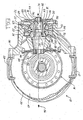
- Figure 1 is a sectional view of a differential in accordance with one embodiment of the present invention.
- Figure 2 is a partial sectional view of a differential in accordance with another embodiment of the present invention.
- FIG. 1 illustrates a differential 10 in accordance with one embodiment of the present invention.
- Differential 10 is provided to allow wheels (not shown) disposed on either side of the vehicle, and supported on axle half shafts (not shown) extending from differential 10, to rotate at different speeds.
- Differential 10 is particularly adapted for use in a heavy truck. It should be understood, however, that the present invention is not limited to use in heavy trucks and may be used in a wide variety of vehicles.
- Differential 10 may include a housing 12, a differential gear assembly 14, a pinion shaft 16, an input yoke 18, a carrier 20, and bearing sets 22, 24.
- Housing 12 provides structural support for the other components of differential 10. Housing 12 also protects the other components of differential 10 from foreign objects and elements. Housing 12 may be made from conventional metals and metal alloys such as steel and may include multiple members 26, 28, 30 that are sized relative to components of differential 10 and coupled together using conventional fasteners (not shown). Member 26 of housing may define an opening 34 at a forward end. Opening 34 may be centered about an axis 36 extending through pinion shaft 16.
- Differential gear assembly 14 is provided to allow the wheels supported on either side of the vehicle to rotate at different speeds.
- Assembly 14 may include a pinion gear 38, a ring gear 40, and a conventional bevel gear set (not shown) disposed within a differential carrier (not shown).
- Pinion gear 38 is provided to transfer torque from pinion shaft 16 to ring gear 40.
- Pinion gear 38 may be made from conventional metals and metal alloys and may comprise a hypoid gear.
- Gear 38 rotates about axis 36.
- Gear 38 is disposed about shaft 165 and may be integral therewith or mounted thereto using a conventional spline connection or in other ways customary in the art.
- Gear 38 may also include a pilot portion 42 extending rearwardly that is supported for rotation by bearings 44 disposed in a pilot web 46 of housing member 26.
- Ring gear 90 is provided to transfer torque from pinion gear 38 to the bevel gear set and is conventional in the art.
- Ring gear 40 may also be made from conventional metals and metal alloys and may also comprise a hypoid gear. Gear 40 is affixed to the carrier or may be integral therewith.
- the bevel gear set (not shown) is provided to transfer torque from ring gear 40 to the axle half shafts supporting the vehicle wheels.
- the bevel gear set is conventional in the art.
- Pinion shaft 16 is provided to transmit power from a power input shaft (not shown) to pinion gear 38 and is conventional in the art.
- Pinion shaft 16 may include a first portion 48 having a first diameter, a second portion 50 having a second diameter greater than the first diameter and a tapered portion 52 joining portions 48, 50.
- Pinion shaft 16 may include a plurality of splines 54 extending axially along portion 48 from a forward end of shaft 16 to tapered portion 52.
- Pinion shaft 16 may also include a threaded shank 56 extending from a forward end of shaft 16 and integral therewith.
- Input yoke 18 is provided to transmit power from a power input shaft (not shown) to pinion shaft 16.
- Yoke 18 may be coupled to the power input shaft through a conventional universal joint (not shown) and is configured for rotation about axis 36.
- Yoke 18 includes a generally cylindrical body 58 with a circular flange 60 radiating outwardly from body 58 at a forward end of body 58.
- Body 58 defines a bore 62 sized to receive pinion shaft 16 and extends axially along shaft 16 to the rearward end of shaft 16 such that one axial end of yoke 18 is proximate pinion gear 38.
- Yoke 18 may include a plurality of splines 64 configured for engagement with splines 54 of pinion shaft 16. In accordance with the present invention, splines 64 may be disposed radially inwardly of bearing set 22. Yoke 18 may be retained on shaft 16 by a nut 66 and a washer (not shown) disposed about stud 56 of shaft 16.
- Carrier 20 is provided to position and support bearing sets 22, 24 within opening 34 of housing 12 and may be made from conventional metals or metal alloys.
- Carrier 20 is generally cylindrical in shape and is sized to be received within opening 34 of housing 12.
- Carrier 20 includes a radially outwardly extending flange 68 at a forward end that abuts a shoulder 70 formed in housing 12 upon installation of carrier 20 within opening 34.
- Carrier 20 may be held within opening 34 by a cap 72 that is fastened to member 26 of housing 12 using conventional fasteners (not shown).
- Carrier 20 is disposed about axis 36 and defines a bore 74 configured to receive bearing sets 22, 24.
- a radially inwardly extending flange 76 within bore 74 defines a pair of shoulders 78, 80 and helps enable proper positioning of bearing sets 22, 24 without the need for spacers or shims.
- Bearings sets 22, 24 are provided to allow rotation of input yoke 18 and pinion shaft 16 relative to carrier 20 and housing 12.
- Bearing sets 22, 24 are conventional in the art and may comprise tapered roller bearings.
- Each bearing set 22, 24 includes a cone 82, 84, respectively, defining an inner bearing race and a cup 86, 88, respectively, defining an outer bearing race.
- Cone 82 of bearing set 22 is in engagement with a shoulder 90 defined in input yoke 18 and cup 86 of bearing set 22 is in engagement with shoulder 78 of carrier 20.
- Cone 84 of bearing set 24 is in engagement with pinion gear 38 while cup 86 of bearing set 24 is in engagement with shoulder 80 of carrier 20.
- bearing sets 22, 24 are disposed about input yoke 18 between yoke 18 and carrier 20.
- cones 82, 84 are supported on body 58 of yoke 18.
- the relative location of bearing sets 22, 24 and input yoke 18 result in a significant improvement as compared to conventional differentials.
- yoke 18 is moved forward in differential 10 thereby enabling a reduction in pinion standout, but still allowing yoke 18 to maintain proper engagement with pinion shaft 16 because the lengths of splines 54, 64 are not reduced.
- bearing capacity remains the same in the inventive differential.
- Differential 110 includes may include many components that are substantially similar to components found in differential 10 described hereinabove including, for example: (i) a housing 112 having a member 114 defining an opening 116 at a forward end centered about an axis 118; (ii) a differential gear assembly including a pinion gear 120; and (iii) a pinion shaft 122 configured for rotation about axis 118 and having a plurality of axially extending splines 124. Accordingly, additional information regarding these components may be obtained hereinabove. Differential 110 may further includes an input yoke 126, a spacer 122, a carrier 130, and bearing sets 132, 134.
- Input yoke 126 is provided to transmit power from a power input shaft (not shown) to pinion shaft 122.
- Yoke 126 may be coupled to the power input shaft through a conventional universal joint (not shown) and is configured for rotation about axis 118.
- Yoke 126 includes a generally cylindrical body 136 with a circular flange 138 radiating outwardly from body 136 at a forward end of body 136.
- Body 136 defines a bore 140 sized to receive pinion shaft 122 and extends axially along shaft 122, terminating at a point intermediate the forward and rearward ends of pinion shaft 122.
- Yoke 126 may include a plurality of splines 142 configured for engagement with splines 124 of pinion shaft 122.
- splines 124 may be disposed radially inwardly of bearing set 132.
- Yoke 126 may be retained on shaft 122 by a nut (not shown) and a washer (not shown) disposed about a threaded stud 144 extending from the forward end of shaft 122.
- Yoke 126 has a stepped outer diameter defining a shoulder 146 for a purpose described hereinbelow.
- Spacer 128 is provided to set bearing preload and maintain the position of bearing sets 132, 134. Spacer 128 is disposed between bearing sets 132, 134 and also between input yoke 126 and bearing set 134. Spacer 128 has a central bore configured to receive pinion shaft 122 and may have a stepped outer diameter as shown in the illustrated embodiment. Together with yoke 126, the forward end of spacer 128 defines a shoulder 148 for a purpose described hereinbelow. Similarly, the rearward end of spacer 128, together with pinion shaft 122, defines a shoulder 150 for a purpose described hereinbelow.
- Carrier 130 is provided to position and support bearing sets 132, 134 within opening 116 of housing 112 and may be made from conventional metals or metal alloys.
- Carrier 130 is generally cylindrical in shape and is sized to be received within opening 116 of housing 112.
- Carrier 130 may be held within opening 116 by a cap (not shown) that is fastened to member 114 of housing 112 using conventional fasteners (not shown) as discussed hereinabove with reference to Figure 1.
- Carrier 130 is disposed about axis 118 and defines a bore 152 configured to receive bearing sets 132, 134.
- Bearings set 132, 134 are provided to allow rotation of input yoke 126 and pinion shaft 122 relative to carrier 130 and housing 112.
- Bearing sets 132, 134 are conventional in the art and may comprise tapered roller bearings.
- Each bearing set 132, 134 includes a cone 154, 156, respectively, defining an inner bearing race and a cup 158, 160, respectively, defining an outer bearing race.
- Cone 154 of bearing set 132 is disposed and retained between shoulders 146, 148, and may be in engagement with one or both of shoulders 146, 148.
- Cone 156 of bearing set 134 is disposed and retained between shoulder 150 and pinion gear 120 and may be in engagement with one or both of shoulder 150 and pinion gear 120.
- bearing set 132 is disposed about input yoke 126 between yoke 126 and carrier 130.
- cone 154 is supported on body 136 of yoke 126.
- the relative locations of bearing set 132 and input yoke 126 again results in a significant improvement as compared to conventional differentials.
- yoke 126 is moved forward in differential 110 thereby enabling a reduction in pinion standout, but still allowing yoke 126 to maintain proper engagement with pinion shaft 122 because the lengths of splines 142, 124, respectively, is not reduced.
- bearing capacity remains the same in the inventive differential.
Landscapes
- Engineering & Computer Science (AREA)
- General Engineering & Computer Science (AREA)
- Mechanical Engineering (AREA)
- Retarders (AREA)
- General Details Of Gearings (AREA)
Applications Claiming Priority (2)
| Application Number | Priority Date | Filing Date | Title |
|---|---|---|---|
| US823479 | 2004-04-13 | ||
| US10/823,479 US7086983B2 (en) | 2001-10-25 | 2004-04-13 | Differential with pinion bearings supported on input yoke |
Publications (2)
| Publication Number | Publication Date |
|---|---|
| EP1586794A2 true EP1586794A2 (fr) | 2005-10-19 |
| EP1586794A3 EP1586794A3 (fr) | 2006-08-23 |
Family
ID=34940821
Family Applications (1)
| Application Number | Title | Priority Date | Filing Date |
|---|---|---|---|
| EP05252325A Withdrawn EP1586794A3 (fr) | 2004-04-13 | 2005-04-13 | Différentiel avec paliers de pignon supporté de la mâchoire d'entrante |
Country Status (3)
| Country | Link |
|---|---|
| US (1) | US7086983B2 (fr) |
| EP (1) | EP1586794A3 (fr) |
| CN (1) | CN1699794A (fr) |
Cited By (2)
| Publication number | Priority date | Publication date | Assignee | Title |
|---|---|---|---|---|
| DE102006046176A1 (de) * | 2006-09-29 | 2008-04-03 | Audi Ag | Befestigungsvorrichtung für eine Zahnradlagerachse eines Getriebes |
| JP2010286011A (ja) * | 2009-06-09 | 2010-12-24 | Gkn Driveline Japan Ltd | 動力伝達装置 |
Families Citing this family (26)
| Publication number | Priority date | Publication date | Assignee | Title |
|---|---|---|---|---|
| US7152502B2 (en) * | 2003-10-31 | 2006-12-26 | Dana Corporation | Bolted pilot web with precision machined bearing stop |
| ITMI20040307A1 (it) * | 2004-02-24 | 2004-05-24 | Iveco Spa | Miglioramenti a un ponte a bracci piantati per veicoli |
| US8678665B2 (en) * | 2007-03-08 | 2014-03-25 | Twin Disc., Inc. | Bearing arrangement for heavy duty marine transmission |
| GB2474973B (en) * | 2008-07-09 | 2012-10-03 | Mclaren Performance Technologies Inc | Axially compact support for a gear within a gearbox |
| DE102009058560A1 (de) * | 2009-12-17 | 2011-06-22 | Daimler AG, 70327 | Lagerungseinrichtung für einen Antriebsstrang eines Kraftwagens |
| US9074677B2 (en) * | 2011-03-14 | 2015-07-07 | Arvinmeritor Technology, Llc | Carrier assembly with threaded adjustment member |
| DE102011007257A1 (de) * | 2011-04-13 | 2012-10-18 | Schaeffler Technologies AG & Co. KG | Antriebsvorrichtung mit wenigstens einer elektrischen Maschine |
| SE537841C2 (sv) * | 2012-05-28 | 2015-11-03 | Scania Cv Ab | Driven axelväxel för ett motorfordon |
| US9103427B2 (en) | 2013-03-15 | 2015-08-11 | American Axle & Manufacturing, Inc. | Axle assembly |
| US9254713B2 (en) | 2013-03-15 | 2016-02-09 | American Axle & Manufacturing, Inc. | Axle assembly with inboard axle shaft bearings that support a differential mechanism |
| US9157515B2 (en) | 2013-03-15 | 2015-10-13 | American Axle & Manufacturing, Inc. | Axle assembly |
| DE102013218434B4 (de) * | 2013-08-08 | 2021-03-04 | Magna powertrain gmbh & co kg | Lagerung |
| DE102013222621A1 (de) | 2013-11-07 | 2015-05-07 | Schaeffler Technologies Gmbh & Co. Kg | Stützanordnung für ein Leichtbaudifferential |
| DE102013226752A1 (de) * | 2013-12-19 | 2015-06-25 | Aktiebolaget Skf | Gehäuse für ein Winkelgetriebe, Winkelgetriebe sowie Verfahren zur Montage eines Winkelgetriebes |
| US9657829B2 (en) * | 2014-10-23 | 2017-05-23 | Arvinmeritor Technology, Llc | Pinion assembly having a bearing support surface |
| US9739360B2 (en) * | 2015-04-09 | 2017-08-22 | Magna Powertrain Of America, Inc. | Power transfer assemblies for motor vehicle drivelines having integrated two-piece pinion shaft and coupling unit |
| US10267401B2 (en) | 2015-11-25 | 2019-04-23 | American Axle & Manufacturing, Inc. | Axle assembly |
| EP3433514B1 (fr) | 2016-03-25 | 2024-05-22 | American Axle & Manufacturing, Inc. | Ensemble essieu de débrayage |
| CN106090035A (zh) * | 2016-08-18 | 2016-11-09 | 北京可以科技有限公司 | 一种带有成角度布置轴承的承载件及轴承安装结构 |
| US10113631B2 (en) | 2017-02-08 | 2018-10-30 | American Axle & Manufacturing, Inc. | Axle assembly having ring gear with unitarily and integrally formed portion of a bearing race |
| US10316950B2 (en) * | 2017-03-10 | 2019-06-11 | Arvinmeritor Technology, Llc | Axle assembly having a drive pinion and a bearing preload element |
| JP6456424B2 (ja) * | 2017-03-21 | 2019-01-23 | 本田技研工業株式会社 | 動力伝達装置の潤滑構造 |
| US11306800B1 (en) * | 2018-07-26 | 2022-04-19 | Timothy Holmes | Speed and torque optimizer for a drive train |
| US10704663B2 (en) | 2018-09-06 | 2020-07-07 | American Axle & Manufacturing, Inc. | Modular disconnecting drive module with torque vectoring augmentation |
| US10927937B2 (en) | 2018-09-06 | 2021-02-23 | American Axle & Manufacturing, Inc. | Modular disconnecting drive module with torque vectoring augmentation |
| US11691506B2 (en) | 2020-09-30 | 2023-07-04 | Gkn Automotive Limited | Shifting mechanism for a vehicle power transfer unit |
Family Cites Families (29)
| Publication number | Priority date | Publication date | Assignee | Title |
|---|---|---|---|---|
| US904774A (en) * | 1907-08-09 | 1908-11-24 | Edward J Gulick | Transmission-gear and casing for automobiles. |
| US1106149A (en) * | 1913-03-21 | 1914-08-04 | Packard Motor Car Co | Gearing. |
| US1657510A (en) * | 1926-03-08 | 1928-01-31 | Int Motor Co | Carrier for floating bevels |
| US2019464A (en) * | 1935-03-28 | 1935-10-29 | Timken Roller Bearing Co | Pinion shaft bearing |
| US2178900A (en) * | 1936-04-13 | 1939-11-07 | Perfecto Gear Differential Co | Speed change axle and means for oiling the same |
| US2147145A (en) * | 1938-03-19 | 1939-02-14 | Eaton Mfg Co | Automotive drive axle |
| US2219025A (en) * | 1940-01-25 | 1940-10-22 | Clark Equipment Co | Differential mechanism |
| US2383954A (en) * | 1942-11-20 | 1945-09-04 | Timken Axle Co Detroit | Drive axle |
| US3015970A (en) * | 1958-11-06 | 1962-01-09 | Mueller Otto | Fluid lock for differential |
| US3572154A (en) * | 1969-05-27 | 1971-03-23 | Clark Equipment Co | Differential assembly |
| NL7009662A (fr) * | 1970-06-30 | 1972-01-03 | ||
| US4095675A (en) * | 1976-07-28 | 1978-06-20 | Rockwell International Corporation | Multi-speed planetary drive axle assembly |
| US4227427A (en) * | 1977-09-08 | 1980-10-14 | Dana Corporation | Drive unit assembly |
| US4468981A (en) * | 1981-10-02 | 1984-09-04 | Rockwell International Corporation | Drive axle and fluid pump assembly |
| JPS58164429A (ja) * | 1982-03-23 | 1983-09-29 | Toyota Motor Corp | エンジン横置方式の自動変速機一体型終減速装置 |
| US4733578A (en) * | 1986-12-31 | 1988-03-29 | Dana Corporation | Bevel gear differential with conical spherical gear seats |
| EP0428075B1 (fr) * | 1989-11-14 | 1995-02-08 | Deere & Company | Axe de transmission et boîte de vitesses |
| DE4007881A1 (de) * | 1990-03-13 | 1991-09-19 | Skf Gmbh | Lagerung einer welle |
| US5098355A (en) * | 1990-12-05 | 1992-03-24 | Eaton Corporation | Floating ring gear and differential gear assembly |
| DE19519304A1 (de) * | 1994-06-04 | 1995-12-07 | Volkswagen Ag | Lagerung einer Getriebewelle |
| JPH09290652A (ja) * | 1996-04-25 | 1997-11-11 | Aisin Seiki Co Ltd | ディファレンシャル装置 |
| US6093127A (en) * | 1998-12-17 | 2000-07-25 | Daimlerchrysler Corporation | High lateral offset front differential |
| DE10043799A1 (de) * | 2000-09-06 | 2002-03-14 | Daimler Chrysler Ag | Achsgetriebe eines Kraftfahrzeugs |
| US6514169B2 (en) * | 2001-05-25 | 2003-02-04 | Dana Corporation | Tandem axle assembly with different hypoid offsets |
| US6719661B2 (en) * | 2001-10-25 | 2004-04-13 | Dana Corporation | Differential with pinion bearings supported on input yoke |
| JP2003156128A (ja) * | 2001-11-20 | 2003-05-30 | Koyo Seiko Co Ltd | ピニオン軸支持用軸受装置 |
| US6755762B2 (en) * | 2002-03-25 | 2004-06-29 | The Timken Company | Axle center with active torque bias control |
| DE10312348B4 (de) * | 2003-03-20 | 2005-06-09 | Gkn Driveline International Gmbh | Differentialgetriebe mit integrierter Sperrkupplung |
| JP4501384B2 (ja) * | 2003-09-16 | 2010-07-14 | 日産自動車株式会社 | 終減速機のドライブピニオン支持構造 |
-
2004
- 2004-04-13 US US10/823,479 patent/US7086983B2/en not_active Expired - Fee Related
-
2005
- 2005-04-13 EP EP05252325A patent/EP1586794A3/fr not_active Withdrawn
- 2005-04-13 CN CNA2005100792853A patent/CN1699794A/zh active Pending
Non-Patent Citations (1)
| Title |
|---|
| None |
Cited By (3)
| Publication number | Priority date | Publication date | Assignee | Title |
|---|---|---|---|---|
| DE102006046176A1 (de) * | 2006-09-29 | 2008-04-03 | Audi Ag | Befestigungsvorrichtung für eine Zahnradlagerachse eines Getriebes |
| DE102006046176B4 (de) * | 2006-09-29 | 2012-12-13 | Audi Ag | Befestigungsvorrichtung für eine Zahnradlagerachse eines Getriebes |
| JP2010286011A (ja) * | 2009-06-09 | 2010-12-24 | Gkn Driveline Japan Ltd | 動力伝達装置 |
Also Published As
| Publication number | Publication date |
|---|---|
| CN1699794A (zh) | 2005-11-23 |
| US7086983B2 (en) | 2006-08-08 |
| US20040259676A1 (en) | 2004-12-23 |
| EP1586794A3 (fr) | 2006-08-23 |
Similar Documents
| Publication | Publication Date | Title |
|---|---|---|
| EP1586794A2 (fr) | Différentiel avec paliers de pignon supporté de la mâchoire d'entrante | |
| US6719661B2 (en) | Differential with pinion bearings supported on input yoke | |
| US10166812B2 (en) | Axle assembly | |
| EP1352771A2 (fr) | Système de répartiteur de puissance d'essieux en tandem incluant une connexion d'arbre de puissance à glissement intérieure | |
| US6254196B1 (en) | Axle hub assembly with removable axle shaft | |
| EP3453555B1 (fr) | Ensemble essieu ayant un ensemble de pignon d'entrainement | |
| EP1605178A2 (fr) | Dispositif de bride pour supporter les coussinets et l'embout d'un arbre d'entraínement | |
| US20070032334A1 (en) | Gear driven direct differential cross | |
| US6884196B1 (en) | Inter-axle differential with improved differential gear mounting arrangement | |
| EP2965922B1 (fr) | Unité de roulement de moyeu à bride | |
| US7699405B2 (en) | Vehicle wheel end assemblies and methods of assembly thereof | |
| US7503867B2 (en) | Bearing arrangement for the input shaft of a forward axle in a tandem axle drive | |
| US8176811B2 (en) | Ribbed cover for drive axle housing | |
| US7258644B2 (en) | Tandem axle carrier structural rib | |
| EP2957432B1 (fr) | Palier de moyeu comportant un moyeu de rotor en alliage léger | |
| US7690449B2 (en) | Output yoke shaft and assembly | |
| US20080063335A1 (en) | Rolling Bearing Assembly | |
| US6557947B1 (en) | Three quarter floating automotive axle | |
| WO2004009392A1 (fr) | Differentiel entre essieux a systeme de paliers ameliore | |
| JP2001163003A (ja) | 車輪駆動用軸受ユニット及び車輪駆動用軸受ユニット用結合部材の製造方法 | |
| EP3734116A1 (fr) | Ensemble différentiel doté d'une couronne dentée en porte-à-faux | |
| JP2002172910A (ja) | 駆動車輪用軸受装置 | |
| JP2008169859A (ja) | 車輪用軸受装置 |
Legal Events
| Date | Code | Title | Description |
|---|---|---|---|
| PUAI | Public reference made under article 153(3) epc to a published international application that has entered the european phase |
Free format text: ORIGINAL CODE: 0009012 |
|
| AK | Designated contracting states |
Kind code of ref document: A2 Designated state(s): AT BE BG CH CY CZ DE DK EE ES FI FR GB GR HU IE IS IT LI LT LU MC NL PL PT RO SE SI SK TR |
|
| AX | Request for extension of the european patent |
Extension state: AL BA HR LV MK YU |
|
| PUAL | Search report despatched |
Free format text: ORIGINAL CODE: 0009013 |
|
| AK | Designated contracting states |
Kind code of ref document: A3 Designated state(s): AT BE BG CH CY CZ DE DK EE ES FI FR GB GR HU IE IS IT LI LT LU MC NL PL PT RO SE SI SK TR |
|
| AX | Request for extension of the european patent |
Extension state: AL BA HR LV MK YU |
|
| AKX | Designation fees paid | ||
| REG | Reference to a national code |
Ref country code: DE Ref legal event code: 8566 |
|
| STAA | Information on the status of an ep patent application or granted ep patent |
Free format text: STATUS: THE APPLICATION IS DEEMED TO BE WITHDRAWN |
|
| 18D | Application deemed to be withdrawn |
Effective date: 20070224 |