EP1586696A1 - Formiersieb - Google Patents
Formiersieb Download PDFInfo
- Publication number
- EP1586696A1 EP1586696A1 EP05102771A EP05102771A EP1586696A1 EP 1586696 A1 EP1586696 A1 EP 1586696A1 EP 05102771 A EP05102771 A EP 05102771A EP 05102771 A EP05102771 A EP 05102771A EP 1586696 A1 EP1586696 A1 EP 1586696A1
- Authority
- EP
- European Patent Office
- Prior art keywords
- machine direction
- threads
- yarns
- stitching
- thread
- Prior art date
- Legal status (The legal status is an assumption and is not a legal conclusion. Google has not performed a legal analysis and makes no representation as to the accuracy of the status listed.)
- Granted
Links
Images


Classifications
-
- D—TEXTILES; PAPER
- D21—PAPER-MAKING; PRODUCTION OF CELLULOSE
- D21F—PAPER-MAKING MACHINES; METHODS OF PRODUCING PAPER THEREON
- D21F1/00—Wet end of machines for making continuous webs of paper
- D21F1/0027—Screen-cloths
- D21F1/0036—Multi-layer screen-cloths
Definitions
- the invention relates to a forming fabric according to the preamble of patent claim 1.
- Forming fabrics are used in the forming section of a paper machine. At the Forming process is a fiber suspension from the headbox of the paper machine on a Forming screen or on two Formiersiebe (Gap - formers) applied. It is the Task of forming fabrics to dewater the fiber suspension and a fibrous web in the dewatering process as little as possible pulp fibers and Fillers from the fiber suspension to be washed out.
- the quality of the fibrous web formed is greatly influenced by the structure of the Determined fibrous web facing surface (paper side) of the forming fabric.
- the Life of the forming fabric is strongly dependent on the structure of the Paper machine facing surface (machine side) of the forming fabric influenced.
- the stitching threads are preferably an integral part of Paper-side weave structure (integral stitching threads), which causes marking tendencies be reduced by the connection of the stitching threads.
- each first and every second binding region is formed by, in the the first and second stitching threads each under at least two and at most three running to each other adjacent lower machine direction threads.
- the binding area in this case the area bounded by the stitching thread of the machine-side weave structure defining one or more lower MD threads span.
- the stitching thread on one side of the paper side Web structure fed to the MD thread then runs under this MD thread and then becomes then led away again from the MD thread to the paper-side weave structure. Of the Bonding area is thus spanned by a lower MD thread.
- the invention is based on the consideration that the connection of the paper side Web structure on the machine-side weave structure in a forming fabric with integral Stapling threads can be improved by applying a stitching thread to the machine-side woven structure and applied in the direction of the machine side Weave structure acting force from a lower (machine side) Machine direction thread (MD thread) on at least two maximum but three lower MD threads is split. That According to the invention is a bond area with two to three lower MD threads.
- a binding region according to the invention is formed by the fact that the Stitching thread runs under all the MD threads of the binding area, thus, in contrast to the case in which the stitching thread in the binding area over one or more lower MD threads would run, the sieve of the invention can be kept thinner.
- a preferred embodiment of the invention therefore provides that between a first and a second binding area a maximum of three lower machine direction threads are arranged.
- the first stitching thread of a pair weaves with a number of upper machine direction threads first segments. Furthermore, the second stitching thread weaves The pair weaves second with a number of other top machine direction threads Segments, wherein the first and second segments in the cross-machine direction are arranged alternately lying one behind the other.
- the segment of the paper-side area woven by a stitching thread is intended to be the segment Web structure defined by one or more top MD threads.
- the stitching thread is from the machine side weave structure fed on one side to the top MD thread, then runs over that top MD thread and then from the top MD thread to the machine side Web structure led away again.
- the segment is characterized by an upper MD thread clamped.
- top MD threads delimit two top MD threads the segment; a first upper MD thread, which the stitching thread from the machine side Web structure is fed and runs over the stitching thread and a second upper MD thread over which the stitching thread runs and of which the stitching thread again the machine-side weave structure is fed, wherein between these two upper MD threads the stitching thread neither goes to the machine-side weave structure nor from this comes.
- the first and the second segments are used by the the upper MD yarns and the upper CMD yarns (CD yarns) educated web structure continued.
- the marking tendency and the planarity of the paper-based web structure has the direct influence of the size of the segments. If the segments are too small form "hard” binding sites with too large Marking tendency. If the segments are too big, the paper-side weave may be bulge in the area of the segments, with the result that the planarity of the paper side Web structure is unsatisfactory. Research has shown that one particular smooth paper-side surface is created when every first and every second Segment each with at least two and a maximum of five mutually adjacent upper Machine direction threads is formed.
- each first and every second transitional area should each have a maximum three mutually adjacent pairs of upper and lower MD threads is formed. This steep connection makes the paper side and the machine side Web structure closer together. By the more intimate connection between the Both weave structures are also the so - called "Edge - Curl - Effect" (bulging of the Edge areas of the screen) reduced.
- planarity of the paper-based web structure can be further improved in this way the first stitching thread of a pair per repeat unit of the weave structure in Cross machine direction runs over and under the same number of upper machine direction threads like the second stitching thread.
- a preferred embodiment of The invention therefore provides that per repeating unit of the web structure in Cross machine direction, the first and the second stitching threads of each pair the same Walk under, over, and between the top and bottom machine direction threads.
- this is the paper-side weave structure of the forming fabric according to the invention designed as a plain weave pattern.
- a preferred embodiment of the invention provides that the first and the second Segments each with three adjacent upper machine direction threads, the first and the second transition regions each with a maximum of two to each other adjacent pairs of upper and lower machine direction threads and the first and the second binding regions each having two lower adjacent ones Machine direction threads are formed.
- the forming fabric according to the invention are different Relationships between upper and lower cross machine direction yarns possible.
- a preferred embodiment of the invention provides that between two to each other adjacent pairs of first and second stitching threads two lower ones Cross-machine direction yarns and an upper cross-machine direction yarn are arranged are. This ratio corresponds to a CD thread ratio of 1: 1.
- a further embodiment of the invention provides that between two to each other adjacent pairs of first and second stitching threads a lower one Cross-machine direction yarn and an upper cross-machine direction yarn arranged is. This ratio corresponds to a CD thread ratio of 2: 1.
- a preferred embodiment of The invention therefore provides that each of the lower cross machine direction yarns respectively over one and then under at least seven adjacent ones Machine direction threads are running. Another advantage of the so - called long floating is that the Proportion of lower CD threads within the screen is reduced, which on the one hand a smaller thickness of the screen makes possible and on the other hand a smaller Drainage resistance can result.
- a further preferred embodiment of the invention provides that at least two Pairs of first and second stitching threads disposed immediately adjacent to each other are. Generally, increasing the number of twine pairs increases the number of tethers increases, thereby improving the connection of the upper weave structure to the lower Web structure and a higher stiffness of the forming fabric is achieved.
- each pair of first and second stitching threads between at least two upper ones Cross-machine direction yarns are arranged.
- a preferred embodiment of the invention provides that at least one Pair of stitching threads is provided, in which between the first stitching thread and the second stitching thread of the pair is arranged a lower cross-machine direction yarn.
- a further preferred embodiment of the invention provides that at least one pair of stitching threads is provided, wherein the first and second stitching thread between at least two lower cross machine direction yarns is arranged.
- a lower attachment point which formed by a lower cross-machine direction yarn under a first lower machine direction yarn and over a second lower adjacent thereto Machine direction yarn runs, the second lower machine direction yarn immediately adjacent to a lower machine direction thread of a first or second binding region is arranged.
- a further preferred embodiment of the invention provides that the second lower Machine direction yarn, a lower machine direction yarn of the first or second Binding area is.
- the Repeat unit is a forming fabric in which the Repeat unit has 8 upper and 8 lower machine direction threads.
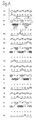
- FIG. 1 shows a repeat unit of the weave pattern of a device according to the invention Forming fabric.
- the forming fabric has a plurality of upper MD yarns 1,3,5,7,9,11,13,15, a Variety of lower MD threads 2,4,6,8,10,12,14,16, a variety of top CD threads T1, T2, T3, T4, a plurality of lower CD threads B1, B2, B3, ..., B8 and pairs of the first ones and second stitching threads I1 and I2, I3 and I4, I5 and I6, I7 and I8.
- the repeat unit 8 has upper and lower 8 Machine direction threads on.
- the repeat unit passes through the lower and upper MD threads 1 through 16, the upper CD threads T1, T2, T3, T4, the lower CD threads B1 to B8 and by the pairs of first and second second stitching threads I1 and I2, I3 and I4, formed I5 and I6, I7 and I8.
- the repeat unit will So formed by 16 MD or warp threads.
- the paper-side weave structure is thereby formed, in which the upper MD threads 1,3,5,7,9,11,13,15 are interwoven with the upper CD threads T1, T2, T3, T4 and in which the upper MD threads 1,3,5,7,9,11,13,15 with the first and second stitching threads 11 and 12, 13th and I4, I5, and I6, I7, and I8 of a pair are each interwoven such that thereby from the upper MD threads 1,3,5,7,9,11,13,15 and the upper CD threads T1, T2, T3, T4 formed web structure is continued.
- the upper CD thread T1 passes over the upper MD threads 1,5,9,13, etc., and below the upper MD threads 3, 7, 11, 15.
- the stitching thread I1 runs in the repeat unit over the upper MD threads 3,7 and below the upper MD thread 5.
- the stitching thread 12 runs in the repeat unit over the upper MD threads 11,15 and below the upper MD thread 13.
- the weaving of the stitching thread 11 forms a first with the upper MD threads 3,5,7 Segment A. Further, the weaving of stitching thread 12 forms with the upper MD threads 11,13,15 a second segment B.
- the first and the second segments are alternately in the CD direction one behind the other, i.e. arranged in the order A, B., whereby by the order of the upper MD threads 1, 3, 5, 7, 9, 11, 13, 15 and the upper CD thread T1 formed weave structure will continue.
- the paper-side weave structure is a plain weave pattern.
- the machine-side weave structure is thereby formed, in which the lower MD threads 2,4,6,8,10,12,14,16 are interwoven with the lower CD threads B1, B2, B3, .... B8.
- the lower CD thread B1 runs over the lower MD thread 2 and then under the seven mutually adjacent MD threads 4,6,8,10,12,14 and 16.
- the course of CD thread B1 over the MD thread 2 defines a lower attachment point I. On the lower Tie-downs will be discussed later.
- machine-side weave structure forms an 8 shaft "Atlas weave pattern”.
- the paper-side and the machine-side weave structures are interconnected, in the lower MD threads 2,4,6,8,10,12,14,16 with the first and second stitching threads 11th and I2, I3 and I4, I5 and I6, I7 and I8 of each pair are interwoven.
- the stitching thread 11 runs under the lower MD threads 12 and 14 in each repeat unit.
- the stitching thread 21 runs under the lower MD threads 4 and 6 in each repeat unit.
- the weaving of the stitching thread 11 with the lower MD threads 12 and 14 forms a first binding area OO. Furthermore, the weaving of the stitching thread 12 forms with the Lower MD threads 4 and 6, a second binding area XX.
- each first binding region OO and every other binding region XX thereby becomes in which the first stitching thread I1 and the second stitching thread 12 are each under two running to each other adjacent lower machine direction threads.
- the first and second binding regions are alternating in the CD direction one behind the other, i. arranged in the order XX, OO.
- first binding region XX formed with 4,6
- second Bonding area OO formed with 12,14
- first segment A formed with 3,5,7) and the first binding region OO (formed with 12,14) is arranged a first transition region in which the first stitching thread I1 extends between the pair of upper and lower machine direction yarns 9 and 10.
- the forming fabric according to the invention of FIG. 1 has a CD yarn ratio of 1: 1.
- a CD yarn ratio of 1: 1 there are always between two mutually adjacent pairs of first and second second stitching threads two lower CMD yarns and an upper one Cross-machine direction yarn arranged.
- the lower CD threads B2 and B3 and the upper CD thread T2 arranged between the stitching thread pairs 11, 12 and 13, 14, the lower CD threads B2 and B3 and the upper CD thread T2 arranged. Since each pair of stitching the weave pattern of an upper CD thread continues thus results in a CD-thread ratio of 1: 1.
- the pair of stitching threads I1 and I2 is between the two two upper cross-machine direction yarns T 1 and T2 arranged. Furthermore, that is A pair of stitching yarns I1 and I2 between the two bottom CMD yarns B1 and B2 arranged.
- the lower attachment points I set. Furthermore, by the course of the lower CD thread B2 on the MD thread 8, the lower attachment points K set.
- a lower attachment point is generally defined by a lower attachment point Cross machine direction yarn under a first lower machine direction yarn and running over a second lower machine direction thread adjacent thereto. That in example, in this example, the first lower MD threads are passed through MD threads 4, 16 (for B1). and 6.10 (for B2), with the second lower MD threads through the lower MD thread 2 (for B1) and 8 (for B2) are formed.
- the lower MD thread 2 is immediately adjacent to the lower MD thread 4 of the second binding region XX.
- FIG. 2 shows, for second repeat units, the arrangement of the attachment sites as well as the Binding regions of the weave pattern of the machine side of the embodiment of FIG. 1.
- Each field represents the area in which the lower MD threads 2,4,6,8,, 10, ... 32 (1 to 16 first repeat unit and 17 to 32 second repeat unit) with the lower CD threads B1, B2, B3, ... B8 or the first stitching threads I1, I3, I5, .. and the second stitching threads I2, I4, I6, ... are interwoven.
- places marked XX indicate second bond areas and those with OO designated locations are first binding areas, some of which correspond to the Figure 1 are marked.
- the places denoted by ⁇ show lower Connection points.
- FIG. 2a shows the arrangement of the binding sites as well as the binding areas of the binding sites Web pattern of the machine side in the case where the first and second stitching threads of the Pairs of stitching threads arranged between two lower cross machine direction yarns are.
- the stitching threads I1 and I2 are between the lower CD threads B1 and B2 arranged. Furthermore, the stitching threads 13 and 14 are between the lower CD threads B3 and B4 arranged.
- FIG. 2b shows the arrangement of the attachment sites as well as the binding regions of the binding sites Web pattern of the machine side in the case where between the first and the second stitching threads of the pairs of stitching threads each a lower CD thread is arranged.
- the two lower CD threads B1 and B2 arranged between the stitching thread I1, the two lower CD threads B1 and B2 arranged. Furthermore, for example, between the stitching thread 12, the two lower CD threads B2 and B3 arranged.
- FIG. 3 shows two repeat units of the weave pattern of FIG second embodiment of the invention in the CD direction with a DC-thread ratio from 3: 2.
Landscapes
- Paper (AREA)
- Woven Fabrics (AREA)
- Chemical Or Physical Treatment Of Fibers (AREA)
- Polishing Bodies And Polishing Tools (AREA)
- Medicinal Preparation (AREA)
Abstract
Description
- wobei eine papierseitige Webstruktur gebildet wird, in dem die oberen Maschinenrichtungsfäden mit den oberen Maschinenquerrichtungsfäden verwoben sind und in dem die oberen Maschinenrichtungsfäden mit ersten und zweiten Heftfäden eines Paares jeweils derart verwoben sind, dass dadurch das von den oberen Maschinenrichtungsfäden und den oberen Maschinenquerrichtungsfäden gebildete Webstruktur fortgesetzt wird,
- wobei eine maschinenseitige Webstruktur gebildet wird, in dem die unteren Maschinenrichtungsfäden mit den unteren Maschinenquerrichtungsfäden verwoben sind, und
- wobei die papierseitige und die maschinenseitige Webstruktur miteinander verbunden sind, in dem der erste Heftfaden jedes Paares mit unteren Maschinenrichtungsfäden verwoben ist und erste Bindungsbereiche bildet und in dem der zweite Heftfaden jedes Paares mit unteren Maschinenrichtungsfäden verwoben ist und zweite Bindungsbereiche bildet und wobei die ersten und zweiten Bindungsbereiche in Maschinenquerrichtung abwechselnd hintereinander liegend angeordnet sind,
- Figur 1
- das Webmuster einer ersten Ausführungsform der Erfindung in CD-Richtung (DC-Verhältnis 1:1),
- Figur 2
- die Anordnung der Anbindestellen sowie der Bindungsbereiche auf der Maschinenseite von erfindungsgemäßen Webmustern,
- Figur 3
- das Webmuster einer zweiten Ausführungsform der Erfindung in CD-Richtung (DC-Verhältnis 3:2).
- 1,3,5,7,...,15
- oberer MD-Faden
- 2,4,6,8,...,16
- unterer MD-Faden
- T1,T2,T3,...
- oberer CD-Faden
- B1,B2,B3,...
- unterer CD-Faden
- A
- erstes Segment
- B
- zweites Segment
- OO
- erster Bindungsbereich
- XX
- zweiter Bindungsbereich
- I,K
- Anbindestelle
Claims (20)
- Formiersieb mit oberen Maschinenrichtungsfäden (1,3,5,7,...,15), oberen Maschinenquerrichtungsfäden (T1,T2,T3,...), unteren Maschinenrichtungsfäden (2,4,6,8,...,16), unteren Maschinenquerrichtungsfäden (B1,B2,B3,...) und Paaren von ersten und zweiten Heftfäden (I1 und I2, I3 und I4,...),dadurch gekennzeichnet, dass zumindest ein erster (OO) und / oder ein zweiter (XX) Bindungsbereich dadurch gebildet wird, in dem der erste Heftfaden (I1,I3,I5,...) und der zweite Heftfaden (I2,I4,I6,...) jeweils unter zumindest zwei und maximal drei zueinander benachbarten unteren Maschinenrichtungsfäden (2,4,6,8,...,16) läuft.wobei eine papierseitige Webstruktur gebildet wird, in dem die oberen Maschinenrichtungsfäden (1,3,5,7,...,15) mit den oberen Maschinenquerrichtungsfäden (T1,T2,T3,...) verwoben sind und in dem die oberen Maschinenrichtungsfäden (1,3,5,7,...,31) mit ersten Heftfäden (I1,I3,I5,...) und mit zweiten Heftfäden (I2,I4,I6,...) eines Paares (I1 und I2, I3 und I4,...) jeweils derart verwoben sind, dass dadurch das von den oberen Maschinenrichtungsfäden (1,3,5,7,...,15) und den oberen Maschinenquerrichtungsfäden (T1,T2,T3,...) gebildete Webstruktur fortgesetzt wird,wobei eine maschinenseitige Webstruktur gebildet wird, in dem die unteren Maschinenrichtungsfäden (2,4,6,8,...,16) mit den unteren Maschinenquerrichtungsfäden (B1,B2,B3,...) verwoben sind, undwobei die papierseitige und die maschinenseitige Webstruktur miteinander verbunden sind, in dem der erste Heftfaden (I1,I3,I5,...) jedes Paares (I1 und I2, I3 und I4,...) mit unteren Maschinenrichtungsfäden (2,4,6,8,...,16) verwoben ist und erste Bindungsbereiche (OO) bildet und in dem der zweite Heftfaden (I2,I4,I6,...) jedes Paares (I1 und I2, I3 und I4,...) mit unteren Maschinenrichtungsfäden (2,4,6,8,...,16) verwoben ist und zweite Bindungsbereiche (XX) bildet und wobei die ersten (OO) und zweiten Bindungsbereiche (XX) in Maschinenquerrichtung abwechselnd hintereinander liegend angeordnet sind,
- Formiersieb mit oberen Maschinenrichtungsfäden (1,3,5,7,...,15), oberen Maschinenquerrichtungsfäden (T1,T2,T3,...), unteren Maschinenrichtungsfäden (2,4,6,8,...,16), unteren Maschinenquerrichtungsfäden (B1,B2,B3,...) und Paaren von ersten und zweiten Heftfäden (I1 und I2,I3 und I4,...),dadurch gekennzeichnet, dass eine untere Anbindestelle (I,K) vorgesehen ist, die dadurch gebildet wird, dass ein unterer Maschinenquerrichtungsfaden (B1,B2,B3,...) unter einem ersten unteren Maschinenrichtungsfaden (2,4,6,8,...,16) und über einem dazu benachbarten zweiten unteren Maschinenrichtungsfaden (2,4,6,8,...,16) läuft, wobei der zweite untere Maschinenrichtungsfaden (2,4,6,8,...,16) unmittelbar benachbart zu einem unteren Maschinenrichtungsfaden (2,4,6,8,...,16) eines ersten (OO) oder zweiten (XX) Bindungsbereichs angeordnet ist.wobei eine papierseitige Webstruktur gebildet wird, in dem die oberen Maschinenrichtungsfäden (1,3,5,7,...,15) mit den oberen Maschinenquerrichtungsfäden (T1,T2,T3,...) verwoben sind und in dem die oberen Maschinenrichtungsfäden (1,3,5,7,...,15) mit ersten Heftfäden (I1,I3,I5,...) und mit zweiten Heftfäden (I2,I4,I6,...) eines Paares von Heftfäden (I1 und I2,I3 und I4,...) jeweils derart verwoben sind, dass dadurch das von den oberen Maschinenrichtungsfäden (1,3,5,7,...,15) und den oberen Maschinenquerrichtungsfäden (T1,T2,T3,...) gebildete Webstruktur fortgesetzt wird,wobei eine maschinenseitige Webstruktur gebildet wird, in dem die unteren Maschinenrichtungsfäden (2,4,6,8,...,16) mit den unteren Maschinenquerrichtungsfäden (B1,B2,B3,...) verwoben sind, undwobei die papierseitige und die maschinenseitige Webstruktur miteinander verbunden sind, in dem der erste Heftfaden (I1,I3,I5,...) jedes Paares (I1 und I2, I3 und I4,...) mit unteren Maschinenrichtungsfäden (2,4,6,8,...,16) verwoben ist und erste Bindungsbereiche (OO) bildet und in dem der zweite Heftfaden (I2,I4,I6,...) jedes Paares (I1 und I2, I3 und I4,...) mit unteren Maschinenrichtungsfäden (2,4,6,8,...,16) verwoben ist und zweite Bindungsbereiche (XX) bildet und wobei die ersten (OO) und zweiten (XX) Bindungsbereiche in Maschinenquerrichtung abwechselnd hintereinander liegend angeordnet sind,
- Formiersieb nach Anspruch 1,
dadurch gekennzeichnet, dass bei jedem ersten (OO) und / oder bei jedem zweiten (XX) Bindungsbereich der erste Heftfaden (I1,I3,I5,...) bzw. der zweite Heftfaden (I2,I4,I6,...) unter zumindest zwei und maximal drei zueinander benachbarten unteren Maschinenrichtungsfäden (2,4,6,8,...,16) läuft. - Formiersieb nach Anspruch 2,
dadurch gekennzeichnet, dass der zweite untere Maschinenrichtungsfaden (2,4,6,8,...,16) ein unterer Maschinenrichtungsfaden (2,4,6,8,...,16) des ersten (OO) oder zweiten (XX) Bindungsbereichs ist. - Formiersieb nach einem der vorangegangenen Ansprüche,
dadurch gekennzeichnet, dass zwischen einem ersten Bindungsbereich (OO) und einem zweiten Bindungsbereich (XX) maximal drei untere Maschinenrichtungsfäden (2,4,6,8,...,16) angeordnet sind. - Formiersieb nach einem der vorangegangenen Ansprüche,
dadurch gekennzeichnet, dass der erste Heftfaden (I1,I3,I5,...) eines Paares mit oberen Maschinenrichtungsfäden (1,3,5,7,...,15) erste Segmente (A) und der zweite Heftfaden (I2,I4,I6,...) des Paares mit oberen Maschinenrichtungsfäden (1,3,5,7,...,31) zweite Segmente (B) bildet, wobei die ersten (A) und zweiten (B) Segmente in Maschinenquerrichtung abwechselnd hintereinander liegend angeordnet sind und wobei jedes erste (A) und jedes zweite (B) Segment jeweils mit zumindest zwei und maximal fünf zueinander benachbarten oberen Maschinenrichtungsfäden (1,3,5,7,...,15) gebildet wird. - Formiersieb nach einem der vorangegangenen Ansprüche,
dadurch gekennzeichnet, dass zwischen jedem ersten Segment (A) und ersten Bindungsbereich (OO) bzw. zwischen jedem zweiten Segment (B) und zweiten Bindungsbereich (XX) jeweils ein erster bzw. zweiter Übergangsbereich ist, in dem der erste Heftfaden (I1,I3,I5,...) bzw. zweite Heftfaden (I2,I4,I6,...)zwischen zueinander benachbarten Paaren (9 und 10, 15 und 16) von oberen und unteren Maschinenrichtungsfäden verläuft, wobei jeder erste und jeder zweite Übergangsbereich jeweils mit maximal drei zueinander benachbarten Paaren (9 und 10, 15 und 16) gebildet wird. - Formiersieb nach einem der vorangegangenen Ansprüche,
dadurch gekennzeichnet, dass die ersten (A) und die zweiten (B) Segmente dadurch gebildet werden, in dem der erste Heftfaden (I1,I3,I5,...) pro Wiederholungseinheit der Webstruktur in Maschinenquerrichtung über und unter gleich vielen oberen Maschinenrichtungsfäden (1,3,5,7,...,15) läuft wie der zweite Heftfaden (I2,I4,I6,...). - Formiersieb nach einem der vorangegangenen Ansprüche,
dadurch gekennzeichnet, dass pro Wiederholungseinheit der Webstruktur in Maschinenquerrichtung die ersten Heftfäden (I1,I3,I5,...) und die zweiten Heftfäden (I2,I4,I6,...) jedes Paares (11 und 12, I3 und I4,...) den gleichen Weg unter, über und zwischen den oberen (1,3,5,7,...,15) und unteren Maschinenrichtungsfäden (2,4,6,8,...,I6) laufen. - Formiersieb nach einem der vorangegangenen Ansprüche,
dadurch gekennzeichnet, dass die papierseitige Webstruktur ein Leinwandbindungsmuster ist. - Formiersieb nach einem der vorangegangenen Ansprüche,
dadurch gekennzeichnet, dass die ersten (A) und die zweiten (B) Segmente jeweils mit drei zueinander benachbarten oberen Maschinenrichtungsfäden (1,3,5,7,...,16), die ersten und die zweiten Übergangsbereiche jeweils mit maximal zwei zueinander benachbarten Paaren (9 und 10, 15 und 16) aus oberen und unteren Maschinenrichtungsfäden und die ersten (OO) und die zweiten (XX) Bindungsbereiche jeweils mit zwei zueinander benachbarten unteren Maschinenrichtungsfäden (2,4,6,8,...,32) gebildet werden. - Formiersieb nach einem der vorangegangenen Ansprüche,
dadurch gekennzeichnet, dass zwischen zwei zueinander benachbarten Paaren (I1 und I2, I3 und I4,...) von ersten Heftfäden (I1,I3,I5,...) und zweiten Heftfäden (I2,I4,I6,...) zwei untere Maschinenquerrichtungsfäden (B1,B2,B3,...) und ein oberer Maschinenquerrichtungsfaden (T1,T2,T3,...) angeordnet sind. - Formiersieb nach einem der Ansprüche 1 bis 11,
dadurch gekennzeichnet, dass zwischen zwei zueinander benachbarten Paaren (I1 und I2, I3 und I4,...) von ersten und zweiten Heftfäden zwei untere Maschinenquerrichtungsfäden (B1,B2,B3,...) und zwei obere Maschinenquerrichtungsfäden (T1,T2,T3,...) angeordnet sind. - Formiersieb nach einem der Ansprüche 1 bis 11,
dadurch gekennzeichnet, dass zwischen zwei zueinander benachbarten Paaren (I1 und I2, I3 und I4,...) von ersten und zweiten Heftfäden ein unterer Maschinenquerrichtungsfaden (B1,B2,B3,...) und ein oberer Maschinenquerrichtungsfaden (T1,T2,T3,...) angeordnet ist. - Formiersieb nach einem der Ansprüche 1 bis 11,
dadurch gekennzeichnet, dass zumindest zwei Paare (I1 und I2, I3 und I4,...) von ersten und zweiten Heftfäden unmittelbar zueinander benachbart angeordnet sind. - Formiersieb nach einem der vorangegangenen Ansprüche,
dadurch gekennzeichnet, dass jeder der unteren Maschinenquerrichtungsfäden (B1,B2,B3,...) jeweils über einen und anschließend unter zumindest sieben zueinander benachbarten unteren Maschinenrichtungsfäden (2,4,6,8,.....,16) läuft. - Formiersieb nach einem der vorangegangenen Ansprüche,
dadurch gekennzeichnet, dass jedes Paar (I1 und I2, I3 und I4,...) von ersten und zweiten Heftfäden zwischen zumindest zwei oberen Maschinenquerrichtungsfäden (T1,T2,T3,...) angeordnet ist. - Formiersieb nach einem der vorangegangenen Ansprüche,
dadurch gekennzeichnet, dass zumindest ein Paar (I1 und I2, I3 und I4,...) von Heftfäden vorgesehen ist, bei dem zwischen dem ersten Heftfaden (I1,I3,I5,...) und dem zweiten Heftfaden (I2,I4,I6,...) des Paares (11 und I2, I3 und 14,...) zumindest ein unterer Maschinenquerrichtungsfaden (B1,B2,B3,...) angeordnet ist. - Formiersieb nach einem der Ansprüche 1 bis 17,
dadurch gekennzeichnet, dass zumindest ein Paar (I1 und I2, I3 und I4,...) von Heftfäden vorgesehen ist, bei dem der erste Heftfaden (I1,I3,I5,...) und der zweite Heftfaden (I2,I4,I6,...) zwischen zumindest zwei unteren Maschinenquerrichtungsfäden (B1,B2,B3,...) angeordnet sind. - Formiersieb nach einem der vorangegangenen Ansprüche,
dadurch gekennzeichnet, dass die Rapporteinheit 16 obere (1,3,5,7,...,15) und 16 untere (2,4,6,8,...,16) Maschinenrichtungsfäden aufweist.
Applications Claiming Priority (2)
| Application Number | Priority Date | Filing Date | Title |
|---|---|---|---|
| DE102004019182A DE102004019182A1 (de) | 2004-04-16 | 2004-04-16 | Formiersieb |
| DE102004019182 | 2004-04-16 |
Publications (2)
| Publication Number | Publication Date |
|---|---|
| EP1586696A1 true EP1586696A1 (de) | 2005-10-19 |
| EP1586696B1 EP1586696B1 (de) | 2008-11-26 |
Family
ID=34939194
Family Applications (1)
| Application Number | Title | Priority Date | Filing Date |
|---|---|---|---|
| EP05102771A Expired - Lifetime EP1586696B1 (de) | 2004-04-16 | 2005-04-08 | Formiersieb |
Country Status (4)
| Country | Link |
|---|---|
| EP (1) | EP1586696B1 (de) |
| AT (1) | ATE415515T1 (de) |
| DE (2) | DE102004019182A1 (de) |
| ES (1) | ES2318420T3 (de) |
Cited By (2)
| Publication number | Priority date | Publication date | Assignee | Title |
|---|---|---|---|---|
| WO2012140992A1 (ja) * | 2011-04-11 | 2012-10-18 | 日本フイルコン株式会社 | 不織布用多層織物 |
| DE102013218465B4 (de) | 2013-09-16 | 2025-08-14 | Voith Patent Gmbh | Formiersieb |
Families Citing this family (1)
| Publication number | Priority date | Publication date | Assignee | Title |
|---|---|---|---|---|
| EP2314762B1 (de) | 2009-10-23 | 2012-09-26 | Heimbach GmbH & Co.KG | Gewebte Papiermaschinenbespannung |
Citations (3)
| Publication number | Priority date | Publication date | Assignee | Title |
|---|---|---|---|---|
| US5437315A (en) * | 1994-03-09 | 1995-08-01 | Huyck Licensco, Inc. | Multilayer forming fabric |
| EP1158090A1 (de) * | 1997-08-01 | 2001-11-28 | Weavexx Corporation | Mehrschichtiges Formiergewebe mit in Papierseite integrierten Nähfadenpaaren |
| WO2005014926A1 (en) * | 2003-07-24 | 2005-02-17 | Voith Fabrics Patent Gmbh | Paper machine fabric |
-
2004
- 2004-04-16 DE DE102004019182A patent/DE102004019182A1/de not_active Withdrawn
-
2005
- 2005-04-08 AT AT05102771T patent/ATE415515T1/de active
- 2005-04-08 ES ES05102771T patent/ES2318420T3/es not_active Expired - Lifetime
- 2005-04-08 EP EP05102771A patent/EP1586696B1/de not_active Expired - Lifetime
- 2005-04-08 DE DE502005006039T patent/DE502005006039D1/de not_active Expired - Lifetime
Patent Citations (3)
| Publication number | Priority date | Publication date | Assignee | Title |
|---|---|---|---|---|
| US5437315A (en) * | 1994-03-09 | 1995-08-01 | Huyck Licensco, Inc. | Multilayer forming fabric |
| EP1158090A1 (de) * | 1997-08-01 | 2001-11-28 | Weavexx Corporation | Mehrschichtiges Formiergewebe mit in Papierseite integrierten Nähfadenpaaren |
| WO2005014926A1 (en) * | 2003-07-24 | 2005-02-17 | Voith Fabrics Patent Gmbh | Paper machine fabric |
Cited By (4)
| Publication number | Priority date | Publication date | Assignee | Title |
|---|---|---|---|---|
| WO2012140992A1 (ja) * | 2011-04-11 | 2012-10-18 | 日本フイルコン株式会社 | 不織布用多層織物 |
| JPWO2012140992A1 (ja) * | 2011-04-11 | 2014-07-28 | 日本フイルコン株式会社 | 不織布用多層織物 |
| US9458559B2 (en) | 2011-04-11 | 2016-10-04 | Nippon Filcon Co., Ltd. | Multi-layer fabric |
| DE102013218465B4 (de) | 2013-09-16 | 2025-08-14 | Voith Patent Gmbh | Formiersieb |
Also Published As
| Publication number | Publication date |
|---|---|
| EP1586696B1 (de) | 2008-11-26 |
| ES2318420T3 (es) | 2009-05-01 |
| ATE415515T1 (de) | 2008-12-15 |
| DE502005006039D1 (de) | 2009-01-08 |
| DE102004019182A1 (de) | 2005-11-10 |
Similar Documents
| Publication | Publication Date | Title |
|---|---|---|
| DE60129391T2 (de) | Dreischichtige Papiermaschinegewebe | |
| DE60104770T2 (de) | Formiergewebe für die Papierherstellung | |
| EP0224276B1 (de) | Bespannung für den Blattbildungsteil einer Papiermaschine | |
| DE69117305T2 (de) | Gewebe für eine papiermaschine oder dergleichen und verfahren zur herstellung eines solchen gewebes | |
| DE69713403T2 (de) | Mehrschichtiges formiergebwebe mit im papierseite integrierten nähfadenpaaren | |
| DE69727715T2 (de) | Papiermachergewebe mit beidseitig alternierenden Bindefäden | |
| DE60319436T2 (de) | Papiermacherformiergewebe | |
| DE60104980T2 (de) | Papiermaschinensieb | |
| EP2470716B1 (de) | Blattbildungssieb | |
| EP1985749B1 (de) | Papiermaschinenbespannung | |
| EP2922995B1 (de) | Papiermaschinensieb, dessen laufseite querfäden mit unterschiedlicher flottierungslänge aufweist | |
| EP1619295B1 (de) | Papiermaschinenbespannung | |
| DE112009001439T5 (de) | Verbundformiersieb mit intrinsischer Kettenbindung und hoher Faserunterstützung | |
| EP2205791A1 (de) | Formiersieb | |
| EP1586696B1 (de) | Formiersieb | |
| EP1619294A2 (de) | Papiermaschinenbespannung | |
| EP0349779A2 (de) | Doppelgewebe als Siebgewebe für die Nasspartie einer Papiermaschine | |
| EP1738020B1 (de) | Sieb, insbesondere papiermaschinensieb | |
| EP1754820B1 (de) | Papiermaschinensieb | |
| EP1798336B1 (de) | Papiermaschinensieb | |
| DE102004035523A1 (de) | Papiermaschinenbespannung | |
| EP2004903B1 (de) | Oberseite, insbesondere papierseite, für ein papiermaschinensieb sowie papiermaschinensieb | |
| DE202006011572U1 (de) | Formiersieb | |
| EP1788151B1 (de) | Papiermaschinensieb | |
| DE102005041042A1 (de) | Papiermaschinensieb |
Legal Events
| Date | Code | Title | Description |
|---|---|---|---|
| PUAI | Public reference made under article 153(3) epc to a published international application that has entered the european phase |
Free format text: ORIGINAL CODE: 0009012 |
|
| AK | Designated contracting states |
Kind code of ref document: A1 Designated state(s): AT BE BG CH CY CZ DE DK EE ES FI FR GB GR HU IE IS IT LI LT LU MC NL PL PT RO SE SI SK TR |
|
| AX | Request for extension of the european patent |
Extension state: AL BA HR LV MK YU |
|
| 17P | Request for examination filed |
Effective date: 20060419 |
|
| AKX | Designation fees paid |
Designated state(s): AT BE BG CH CY CZ DE DK EE ES FI FR GB GR HU IE IS IT LI LT LU MC NL PL PT RO SE SI SK TR |
|
| RAP1 | Party data changed (applicant data changed or rights of an application transferred) |
Owner name: VOITH PATENT GMBH |
|
| 17Q | First examination report despatched |
Effective date: 20070702 |
|
| GRAP | Despatch of communication of intention to grant a patent |
Free format text: ORIGINAL CODE: EPIDOSNIGR1 |
|
| GRAS | Grant fee paid |
Free format text: ORIGINAL CODE: EPIDOSNIGR3 |
|
| GRAA | (expected) grant |
Free format text: ORIGINAL CODE: 0009210 |
|
| AK | Designated contracting states |
Kind code of ref document: B1 Designated state(s): AT BE BG CH CY CZ DE DK EE ES FI FR GB GR HU IE IS IT LI LT LU MC NL PL PT RO SE SI SK TR |
|
| REG | Reference to a national code |
Ref country code: GB Ref legal event code: FG4D Free format text: NOT ENGLISH |
|
| REG | Reference to a national code |
Ref country code: CH Ref legal event code: EP |
|
| REG | Reference to a national code |
Ref country code: IE Ref legal event code: FG4D Free format text: LANGUAGE OF EP DOCUMENT: GERMAN |
|
| REF | Corresponds to: |
Ref document number: 502005006039 Country of ref document: DE Date of ref document: 20090108 Kind code of ref document: P |
|
| REG | Reference to a national code |
Ref country code: SE Ref legal event code: TRGR |
|
| PG25 | Lapsed in a contracting state [announced via postgrant information from national office to epo] |
Ref country code: LT Free format text: LAPSE BECAUSE OF FAILURE TO SUBMIT A TRANSLATION OF THE DESCRIPTION OR TO PAY THE FEE WITHIN THE PRESCRIBED TIME-LIMIT Effective date: 20081126 |
|
| REG | Reference to a national code |
Ref country code: ES Ref legal event code: FG2A Ref document number: 2318420 Country of ref document: ES Kind code of ref document: T3 |
|
| NLV1 | Nl: lapsed or annulled due to failure to fulfill the requirements of art. 29p and 29m of the patents act | ||
| PG25 | Lapsed in a contracting state [announced via postgrant information from national office to epo] |
Ref country code: IS Free format text: LAPSE BECAUSE OF FAILURE TO SUBMIT A TRANSLATION OF THE DESCRIPTION OR TO PAY THE FEE WITHIN THE PRESCRIBED TIME-LIMIT Effective date: 20090326 Ref country code: SI Free format text: LAPSE BECAUSE OF FAILURE TO SUBMIT A TRANSLATION OF THE DESCRIPTION OR TO PAY THE FEE WITHIN THE PRESCRIBED TIME-LIMIT Effective date: 20081126 Ref country code: NL Free format text: LAPSE BECAUSE OF FAILURE TO SUBMIT A TRANSLATION OF THE DESCRIPTION OR TO PAY THE FEE WITHIN THE PRESCRIBED TIME-LIMIT Effective date: 20081126 Ref country code: PL Free format text: LAPSE BECAUSE OF FAILURE TO SUBMIT A TRANSLATION OF THE DESCRIPTION OR TO PAY THE FEE WITHIN THE PRESCRIBED TIME-LIMIT Effective date: 20081126 |
|
| REG | Reference to a national code |
Ref country code: IE Ref legal event code: FD4D |
|
| PG25 | Lapsed in a contracting state [announced via postgrant information from national office to epo] |
Ref country code: IE Free format text: LAPSE BECAUSE OF FAILURE TO SUBMIT A TRANSLATION OF THE DESCRIPTION OR TO PAY THE FEE WITHIN THE PRESCRIBED TIME-LIMIT Effective date: 20081126 Ref country code: DK Free format text: LAPSE BECAUSE OF FAILURE TO SUBMIT A TRANSLATION OF THE DESCRIPTION OR TO PAY THE FEE WITHIN THE PRESCRIBED TIME-LIMIT Effective date: 20081126 Ref country code: BG Free format text: LAPSE BECAUSE OF FAILURE TO SUBMIT A TRANSLATION OF THE DESCRIPTION OR TO PAY THE FEE WITHIN THE PRESCRIBED TIME-LIMIT Effective date: 20090226 Ref country code: EE Free format text: LAPSE BECAUSE OF FAILURE TO SUBMIT A TRANSLATION OF THE DESCRIPTION OR TO PAY THE FEE WITHIN THE PRESCRIBED TIME-LIMIT Effective date: 20081126 Ref country code: RO Free format text: LAPSE BECAUSE OF FAILURE TO SUBMIT A TRANSLATION OF THE DESCRIPTION OR TO PAY THE FEE WITHIN THE PRESCRIBED TIME-LIMIT Effective date: 20081126 |
|
| PG25 | Lapsed in a contracting state [announced via postgrant information from national office to epo] |
Ref country code: CZ Free format text: LAPSE BECAUSE OF FAILURE TO SUBMIT A TRANSLATION OF THE DESCRIPTION OR TO PAY THE FEE WITHIN THE PRESCRIBED TIME-LIMIT Effective date: 20081126 Ref country code: PT Free format text: LAPSE BECAUSE OF FAILURE TO SUBMIT A TRANSLATION OF THE DESCRIPTION OR TO PAY THE FEE WITHIN THE PRESCRIBED TIME-LIMIT Effective date: 20090427 |
|
| PG25 | Lapsed in a contracting state [announced via postgrant information from national office to epo] |
Ref country code: SK Free format text: LAPSE BECAUSE OF FAILURE TO SUBMIT A TRANSLATION OF THE DESCRIPTION OR TO PAY THE FEE WITHIN THE PRESCRIBED TIME-LIMIT Effective date: 20081126 |
|
| PLBE | No opposition filed within time limit |
Free format text: ORIGINAL CODE: 0009261 |
|
| STAA | Information on the status of an ep patent application or granted ep patent |
Free format text: STATUS: NO OPPOSITION FILED WITHIN TIME LIMIT |
|
| BERE | Be: lapsed |
Owner name: VOITH PATENT G.M.B.H. Effective date: 20090430 |
|
| 26N | No opposition filed |
Effective date: 20090827 |
|
| REG | Reference to a national code |
Ref country code: CH Ref legal event code: PL |
|
| PG25 | Lapsed in a contracting state [announced via postgrant information from national office to epo] |
Ref country code: CH Free format text: LAPSE BECAUSE OF NON-PAYMENT OF DUE FEES Effective date: 20090430 Ref country code: LI Free format text: LAPSE BECAUSE OF NON-PAYMENT OF DUE FEES Effective date: 20090430 |
|
| PG25 | Lapsed in a contracting state [announced via postgrant information from national office to epo] |
Ref country code: MC Free format text: LAPSE BECAUSE OF NON-PAYMENT OF DUE FEES Effective date: 20090430 |
|
| PG25 | Lapsed in a contracting state [announced via postgrant information from national office to epo] |
Ref country code: BE Free format text: LAPSE BECAUSE OF NON-PAYMENT OF DUE FEES Effective date: 20090430 |
|
| PG25 | Lapsed in a contracting state [announced via postgrant information from national office to epo] |
Ref country code: GR Free format text: LAPSE BECAUSE OF FAILURE TO SUBMIT A TRANSLATION OF THE DESCRIPTION OR TO PAY THE FEE WITHIN THE PRESCRIBED TIME-LIMIT Effective date: 20090227 |
|
| PG25 | Lapsed in a contracting state [announced via postgrant information from national office to epo] |
Ref country code: LU Free format text: LAPSE BECAUSE OF NON-PAYMENT OF DUE FEES Effective date: 20090408 |
|
| PG25 | Lapsed in a contracting state [announced via postgrant information from national office to epo] |
Ref country code: HU Free format text: LAPSE BECAUSE OF FAILURE TO SUBMIT A TRANSLATION OF THE DESCRIPTION OR TO PAY THE FEE WITHIN THE PRESCRIBED TIME-LIMIT Effective date: 20090527 |
|
| PGFP | Annual fee paid to national office [announced via postgrant information from national office to epo] |
Ref country code: ES Payment date: 20110426 Year of fee payment: 7 |
|
| PG25 | Lapsed in a contracting state [announced via postgrant information from national office to epo] |
Ref country code: TR Free format text: LAPSE BECAUSE OF FAILURE TO SUBMIT A TRANSLATION OF THE DESCRIPTION OR TO PAY THE FEE WITHIN THE PRESCRIBED TIME-LIMIT Effective date: 20081126 |
|
| PGFP | Annual fee paid to national office [announced via postgrant information from national office to epo] |
Ref country code: GB Payment date: 20110421 Year of fee payment: 7 Ref country code: AT Payment date: 20110414 Year of fee payment: 7 |
|
| PG25 | Lapsed in a contracting state [announced via postgrant information from national office to epo] |
Ref country code: CY Free format text: LAPSE BECAUSE OF FAILURE TO SUBMIT A TRANSLATION OF THE DESCRIPTION OR TO PAY THE FEE WITHIN THE PRESCRIBED TIME-LIMIT Effective date: 20081126 |
|
| PGFP | Annual fee paid to national office [announced via postgrant information from national office to epo] |
Ref country code: IT Payment date: 20110419 Year of fee payment: 7 |
|
| REG | Reference to a national code |
Ref country code: AT Ref legal event code: MM01 Ref document number: 415515 Country of ref document: AT Kind code of ref document: T Effective date: 20120408 |
|
| GBPC | Gb: european patent ceased through non-payment of renewal fee |
Effective date: 20120408 |
|
| PG25 | Lapsed in a contracting state [announced via postgrant information from national office to epo] |
Ref country code: GB Free format text: LAPSE BECAUSE OF NON-PAYMENT OF DUE FEES Effective date: 20120408 Ref country code: AT Free format text: LAPSE BECAUSE OF NON-PAYMENT OF DUE FEES Effective date: 20120408 |
|
| PG25 | Lapsed in a contracting state [announced via postgrant information from national office to epo] |
Ref country code: IT Free format text: LAPSE BECAUSE OF NON-PAYMENT OF DUE FEES Effective date: 20120408 |
|
| REG | Reference to a national code |
Ref country code: ES Ref legal event code: FD2A Effective date: 20130715 |
|
| PG25 | Lapsed in a contracting state [announced via postgrant information from national office to epo] |
Ref country code: ES Free format text: LAPSE BECAUSE OF NON-PAYMENT OF DUE FEES Effective date: 20120409 |
|
| REG | Reference to a national code |
Ref country code: FR Ref legal event code: PLFP Year of fee payment: 12 |
|
| REG | Reference to a national code |
Ref country code: FR Ref legal event code: PLFP Year of fee payment: 13 |
|
| REG | Reference to a national code |
Ref country code: FR Ref legal event code: PLFP Year of fee payment: 14 |
|
| PGFP | Annual fee paid to national office [announced via postgrant information from national office to epo] |
Ref country code: DE Payment date: 20240418 Year of fee payment: 20 |
|
| PGFP | Annual fee paid to national office [announced via postgrant information from national office to epo] |
Ref country code: FR Payment date: 20240426 Year of fee payment: 20 Ref country code: FI Payment date: 20240418 Year of fee payment: 20 |
|
| PGFP | Annual fee paid to national office [announced via postgrant information from national office to epo] |
Ref country code: SE Payment date: 20240418 Year of fee payment: 20 |
|
| REG | Reference to a national code |
Ref country code: DE Ref legal event code: R071 Ref document number: 502005006039 Country of ref document: DE |
|
| REG | Reference to a national code |
Ref country code: SE Ref legal event code: EUG |