EP1586268A2 - Lanzette - Google Patents
Lanzette Download PDFInfo
- Publication number
- EP1586268A2 EP1586268A2 EP05252403A EP05252403A EP1586268A2 EP 1586268 A2 EP1586268 A2 EP 1586268A2 EP 05252403 A EP05252403 A EP 05252403A EP 05252403 A EP05252403 A EP 05252403A EP 1586268 A2 EP1586268 A2 EP 1586268A2
- Authority
- EP
- European Patent Office
- Prior art keywords
- arm assembly
- user
- finger
- force
- lower arm
- Prior art date
- Legal status (The legal status is an assumption and is not a legal conclusion. Google has not performed a legal analysis and makes no representation as to the accuracy of the status listed.)
- Withdrawn
Links
Images


Classifications
-
- A—HUMAN NECESSITIES
- A61—MEDICAL OR VETERINARY SCIENCE; HYGIENE
- A61B—DIAGNOSIS; SURGERY; IDENTIFICATION
- A61B5/00—Measuring for diagnostic purposes; Identification of persons
- A61B5/14—Devices for taking samples of blood ; Measuring characteristics of blood in vivo, e.g. gas concentration within the blood, pH-value of blood
- A61B5/1405—Devices for taking blood samples
-
- A—HUMAN NECESSITIES
- A61—MEDICAL OR VETERINARY SCIENCE; HYGIENE
- A61B—DIAGNOSIS; SURGERY; IDENTIFICATION
- A61B5/00—Measuring for diagnostic purposes; Identification of persons
- A61B5/15—Devices for taking samples of blood
- A61B5/150007—Details
- A61B5/150206—Construction or design features not otherwise provided for; manufacturing or production; packages; sterilisation of piercing element, piercing device or sampling device
-
- A—HUMAN NECESSITIES
- A61—MEDICAL OR VETERINARY SCIENCE; HYGIENE
- A61B—DIAGNOSIS; SURGERY; IDENTIFICATION
- A61B5/00—Measuring for diagnostic purposes; Identification of persons
-
- A—HUMAN NECESSITIES
- A61—MEDICAL OR VETERINARY SCIENCE; HYGIENE
- A61B—DIAGNOSIS; SURGERY; IDENTIFICATION
- A61B5/00—Measuring for diagnostic purposes; Identification of persons
- A61B5/14—Devices for taking samples of blood ; Measuring characteristics of blood in vivo, e.g. gas concentration within the blood, pH-value of blood
-
- A—HUMAN NECESSITIES
- A61—MEDICAL OR VETERINARY SCIENCE; HYGIENE
- A61B—DIAGNOSIS; SURGERY; IDENTIFICATION
- A61B5/00—Measuring for diagnostic purposes; Identification of persons
- A61B5/15—Devices for taking samples of blood
- A61B5/150007—Details
- A61B5/150015—Source of blood
- A61B5/150022—Source of blood for capillary blood or interstitial fluid
-
- A—HUMAN NECESSITIES
- A61—MEDICAL OR VETERINARY SCIENCE; HYGIENE
- A61B—DIAGNOSIS; SURGERY; IDENTIFICATION
- A61B5/00—Measuring for diagnostic purposes; Identification of persons
- A61B5/15—Devices for taking samples of blood
- A61B5/150007—Details
- A61B5/150053—Details for enhanced collection of blood or interstitial fluid at the sample site, e.g. by applying compression, heat, vibration, ultrasound, suction or vacuum to tissue; for reduction of pain or discomfort; Skin piercing elements, e.g. blades, needles, lancets or canulas, with adjustable piercing speed
- A61B5/150061—Means for enhancing collection
-
- A—HUMAN NECESSITIES
- A61—MEDICAL OR VETERINARY SCIENCE; HYGIENE
- A61B—DIAGNOSIS; SURGERY; IDENTIFICATION
- A61B5/00—Measuring for diagnostic purposes; Identification of persons
- A61B5/15—Devices for taking samples of blood
- A61B5/150007—Details
- A61B5/150374—Details of piercing elements or protective means for preventing accidental injuries by such piercing elements
- A61B5/150381—Design of piercing elements
- A61B5/150412—Pointed piercing elements, e.g. needles, lancets for piercing the skin
-
- A—HUMAN NECESSITIES
- A61—MEDICAL OR VETERINARY SCIENCE; HYGIENE
- A61B—DIAGNOSIS; SURGERY; IDENTIFICATION
- A61B5/00—Measuring for diagnostic purposes; Identification of persons
- A61B5/15—Devices for taking samples of blood
- A61B5/150007—Details
- A61B5/150748—Having means for aiding positioning of the piercing device at a location where the body is to be pierced
-
- A—HUMAN NECESSITIES
- A61—MEDICAL OR VETERINARY SCIENCE; HYGIENE
- A61B—DIAGNOSIS; SURGERY; IDENTIFICATION
- A61B5/00—Measuring for diagnostic purposes; Identification of persons
- A61B5/15—Devices for taking samples of blood
- A61B5/151—Devices specially adapted for taking samples of capillary blood, e.g. by lancets, needles or blades
- A61B5/15101—Details
- A61B5/15103—Piercing procedure
- A61B5/15107—Piercing being assisted by a triggering mechanism
- A61B5/15111—Semi-automatically triggered, e.g. at the end of the cocking procedure, for instance by biasing the main drive spring or when reaching sufficient contact pressure, the piercing device is automatically triggered without any deliberate action by the user
-
- A—HUMAN NECESSITIES
- A61—MEDICAL OR VETERINARY SCIENCE; HYGIENE
- A61B—DIAGNOSIS; SURGERY; IDENTIFICATION
- A61B5/00—Measuring for diagnostic purposes; Identification of persons
- A61B5/15—Devices for taking samples of blood
- A61B5/151—Devices specially adapted for taking samples of capillary blood, e.g. by lancets, needles or blades
- A61B5/15101—Details
- A61B5/15115—Driving means for propelling the piercing element to pierce the skin, e.g. comprising mechanisms based on shape memory alloys, magnetism, solenoids, piezoelectric effect, biased elements, resilient elements, vacuum or compressed fluids
- A61B5/15117—Driving means for propelling the piercing element to pierce the skin, e.g. comprising mechanisms based on shape memory alloys, magnetism, solenoids, piezoelectric effect, biased elements, resilient elements, vacuum or compressed fluids comprising biased elements, resilient elements or a spring, e.g. a helical spring, leaf spring, or elastic strap
Definitions
- the present invention relates, in general, to fluid extraction apparatus and, in particular, to apparatus for extracting bodily fluid and associated methods.
- a variety of medical conditions call for the monitoring of an analyte concentration (e.g., glucose concentration) in a blood, interstitial fluid or other bodily fluid sample.
- analyte concentration e.g., glucose concentration
- a bodily fluid sample from a target site (e.g., a dermal tissue target site) on a user's finger.
- the extraction (also referred to as "expression") of a blood sample from a user's finger generally involves lancing the dermal tissue target site and applying pressure in the vicinity of the lanced site to express the blood sample.
- the dermal tissue target site is on a user's finger
- the pressure ring is employed to apply pressure against the dermal tissue target site either prior to, and/or after, lancing.
- a relatively shallow penetration depth such as a penetration depth in the range of 0.5 mm to 1.0 mm.
- expressing a bodily fluid sample from a target site that has been lanced to a relatively shallow penetration depth requires a greater amount of applied pressure than expressing from a target site that has been lanced to a relatively deep penetration depth.
- the strength and dexterity necessary to apply the required pressure e.g., an applied pressure of 15N or more around a dermal tissue target site at the end of a finger
- the required pressure e.g., an applied pressure of 15N or more around a dermal tissue target site at the end of a finger
- an apparatus for extracting bodily fluid from a target site that facilitates the application of pressure to the target site, yet is simple and intuitive to operate. Furthermore, the apparatus should be compact and not require the use of expensive and/or bulky motorized components. Also needed is a process for extracting a bodily fluid sample that is simple and intuitive.
- Apparatus for extracting bodily fluid facilitate the application of pressure to a target site, yet are simple and intuitive to operate. Furthermore, the apparatus are compact and do not require the use of expensive and/or bulky motorized components. Certain embodiments can be operated with one hand and without the separate actuation of motors or other bulky components.
- An apparatus for extracting bodily fluid includes a housing, a lancing mechanism attached to the housing and a clamping mechanism attached to the housing.
- the clamping mechanism includes an upper arm assembly and a lower arm assembly.
- the upper and lower arm assemblies are operatively connected such that when a user's finger applies a predetermined user force to the lower arm assembly and displaces the lower arm assembly from a first position to a second position, the upper arm assembly and lower arm assembly cooperate to engage the user's finger with a compressive force that is greater than the predetermined user force.
- the lancing mechanism is configured to lance a target site on the user's finger while the upper arm assembly and lower arm assembly are cooperating to engage the user's finger. Thereafter, the compressive force serves to extract a bodily fluid sample from the lanced target site.
- the upper and lower arm assemblies can be operatively connected by, for example, a mechanical linkage(s) that employ mechanical advantage to couple the predetermined user force with the compressive force. Because of the mechanical advantage of the mechanical linkage, the compressive force is greater than the predetermined user force.
- a force limiting means such as a force limiting spring that prevents the compressive force from exceeding a predetermined level.
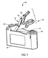
- FIGs. 1, 2A, 2B, 2C and 4 are various depictions of an apparatus 100 for extracting bodily fluid (e.g., whole blood) from a target site (such as a dermal tissue target site on a user's finger) according to the present invention.
- Apparatus 100 includes a housing 102, a lancing mechanism 104 attached to housing 102 and a clamping mechanism 106 also attached to housing 102.
- Clamping mechanism 106 includes a lower arm assembly 108 and an upper arm assembly 110.
- Lancing mechanism 104 can include means for measuring, analyzing and displaying an analyte concentration of a bodily fluid sample extracted by apparatus 100.
- any suitable lancing mechanism can be employed in apparatus according to the present invention.
- An example of a suitable lancing mechanism is described in US. Patent No. 6,197,040, which is hereby fully incorporated herein by reference.
- lancing mechanism 104 includes a skin probe 112 and a dermal tissue penetration member (not shown).
- Skin probe 112 is configured to limit the depth to which the dermal tissue penetration member can penetrate a target site (e.g., a dermal tissue target site) when apparatus 100 is employed to extract a bodily fluid sample.
- a target site e.g., a dermal tissue target site
- Any suitable skin probe known to one skilled in the art can be employed in embodiments of the present invention.
- a non-limiting example of a suitable skin probe is described in co-pending U.S. Patent Application No. 10/690,083.
- skin probe 112 can be either moveable or fixed relative to housing 102.
- Dermal tissue penetration members employed in embodiments of the present invention can be a conventional lancet, as is known to those skilled in the art, or can be part of an integrated medical device that includes a dermal tissue penetration member and a test strip, examples of which are described in International Application No. PCT/GB01/05634 (published as WO 02/49507 on June 27, 2002) and U.S. Patent Application No. 10/143,399, both of which are fully incorporated herein by reference.
- upper and lower arm assemblies 110 and 108 are operatively connected such that when a user's finger applies a predetermined user force to lower arm assembly 108 and displaces lower arm assembly 108 from a first position to a second position (depicted in FIG. 2C), upper arm assembly 110 and lower arm assembly 108 cooperate to engage the user's finger with a compressive force that is greater than the predetermined user force.
- lancing mechanism 104 is configured to lance a target site on the user's finger while upper arm assembly 110 and lower arm assembly 108 are cooperating to engage the user's finger. Thereafter, the compressive force serves to extract a bodily fluid sample from the lanced target site.
- clamping mechanism 106 is pivotally connected to housing 102 and configured to allow one-handed operation of apparatus 100 with relatively effortless user force while facilitating the extraction of a bodily fluid sample (e.g., a blood sample) out of a lanced target site (such as a lanced dermal tissue target site) without manipulation (e.g., squeezing and/or milking) of the target site subsequent to lancing.
- a bodily fluid sample e.g., a blood sample
- a lanced target site such as a lanced dermal tissue target site
- manipulation e.g., squeezing and/or milking
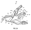
- lower arm assembly 108 includes a body 114 with a proximal end 116, a distal end 118, a body top surface 120 and a body bottom surface 122.
- Distal end 118 is configured to accommodate the shape of lancing mechanism 104 and can be, for example, step-shaped in cross-section.
- Distal end 118 includes a lower lip 124 and a pressure ring 126 for engaging a target site (e.g., a dermal tissue target site of a user's finger F as depicted in FIG. 2C).
- Pressure ring 126 includes a rim 128 surrounding an opening 130 for skin probe 112 the to extend through.
- Rim 128 can be, for example, flat, raised and/or contoured to accommodate different target sites.
- Opening 130 can be any suitable shape including, but not limited to, circular, oval, square, triangular, hexagonal and octagonal shapes.
- Pressure ring 126 can be removable or permanently attached to body 114.
- Non-limiting examples of pressure rings that can be employed in embodiments of the present invention are described in U.S. Patent Application Nos. 09/877514 (published as US 2002/0016606 on February 7, 2002) and 10/653,023, both of which are hereby fully incorporated by reference.
- Pressure ring 126 can be formed of relatively rigid plastic material including, but not limited to, polystyrene, polycarbonate and polyester, or of relatively resiliently deformable material including, but not limited to, elastomeric materials, polymeric materials, polyurethane materials, latex materials, silicone materials and any combinations thereof.
- Lower arm assembly's proximal end 116 includes a means for limiting the compressive force applied to user's finger F, namely a force limiting arm 132 and a force limiting spring 134 that are operatively connected to limit the compressive force.
- Force limiting arm 132 is nested within body 114 and extends from lower arm assembly's proximal end 116 to approximately the center of body 114.
- Force limiting arm 132 and lower arm assembly 108 are pivotally attached to housing 102 at lower pivot axis 136.
- Force limiting arm 132 is also pivotally attached to approximately the center of upper arm assembly 110.
- Force limiting spring 134 is attached to force limiting arm 132 by a screw 140 or other suitable means such as a weld or adhesive.
- Body 114 and force limiting arm 132 can be formed, for example, of rigid materials including polycarbonate, polystyrene or metal.
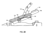
- the angle ⁇ formed between lower arm assembly 108 and plane P can range from about 0 to about 45 degrees during operation of apparatus 100.
- force limiting spring 134 extends from about the center of force limiting arm 132 internally through body 114 of lower arm assembly 108 and exits body 114 at lower lip 124 such that when ⁇ is about 0 degrees and a user's finger F is engaged (see FIG. 2C), force limiting arm 132 rotates counterclockwise about lower pivot axis 136, causing force limiting spring 134 to deflect against lower lip 124.
- Force limiting spring 134 therefore, beneficially limits the amount of compressive force applied to a user's finger F engaged in clamping mechanism 106. In such a circumstance, angle ⁇ is formed between force limiting arm 132 and lower arm assembly's body 114 (see FIG. 2C).
- Angle ⁇ can range from, for example, approximately 0 degrees to 20 degrees.
- force limiting spring 134 or other suitable means for limiting the compressive force as would be known to one skilled in the art once apprised of the present disclosure
- This can be accomplished, for example, by providing for the upper and lower arm assemblies to deform and/or deflect in a manner that mitigates the compressive force that would otherwise occur in a completely rigid clamping mechanism.
- Upper arm assembly 110 includes substantially parallel upper arms 142A and 142B and an upper compression surface 144 (see, for example, FIG. 2A).
- Upper arms 142A and 142B each include a cam portion 146 and are each pivotally attached to force limiting arm 132 at upper pivot axis 148.
- An angle ⁇ formed between lower arm assembly 108 and upper arms 142A, 142B (shown in FIG. 2B) can range from 0 degrees to 180 degrees during operation of apparatus 100.
- Cam portions 146 are in contact with sliding surfaces 150 of housing 102. When upper arms 142A, 142B rotate about upper pivot axes 148, cam portions 146 slide along sliding surfaces 150.
- Upper compression surface 144 applies pressure against the top of user's finger F when user's finger F is engaged with clamping mechanism 106 and thereby aids in the extraction of bodily fluid from user's finger F.
- Upper compression surface 144 can be any suitable upper compression surface including, but not limited to, a curved upper compression surface, an angled upper compression surface, a multi-sided upper compression surface or the surface of two cylindrical bushings.
- upper compression surface 144 can be formed of flexible material including, but not limited to, leather, artificial leather, nylon strapping, rubber, or a semi-rigid plastic such as vinyl or polypropylene.
- upper compression surface 144 is removably attached to upper arms 142A, 142B by screws 152.
- Upper compression surface 144 can also be adhered to upper arms 142A, 142B by techniques known to those skilled in the art, including double-sided heat-sealed gluing or double-sided pressure sensitive adhesion.
- Upper compression surface 144 can also be sewn or riveted onto upper arms 142A, 142B.
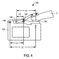
- FIG. 3A As user's finger F is urged toward pressure ring 126, a downward force F1 is created by finger bone FB of user's finger F. Pressure ring's rim 128 reacts with an equal and opposite force Fc against the bottom side of user's finger F. As F1 increases, a pressurized skin bulge B can be created.
- Distances L1, L2, L3 and L4 can be, for example, in the ranges of about 15 mm to 32 mm, 30 mm to 60 mm, 8 mm to 16 mm and 22 mm to 44 mm, respectively.
- L1 32 mm
- L2 60 mm
- L3 16 mm
- L4 44 mm
- 68% of the compressive force Fc is generated by upper compression surface 144 of clamping mechanism 106 (i.e., F2) and 32% of the compressive force Fc is generated by a user's finger F (i.e., F1).
- apparatus for extracting bodily fluid are configured such that movement of the lower arm assembly from a first position to a second position is translated into movement of the upper arm assembly in the same direction as the lower arm assembly such that the distance between the upper and lower arm assemblies is decreased.
- a mechanical advantage is provided when this configuration provides for a portion of Fc to be provided by F2.
- the compressive force Fc required to successfully extract a bodily fluid sample from a dermal tissue target site of a user's finger can be as high as approximately 18N.
- a user can experience discomfort when applying a force F 1 that is greater than 10N.
- the force required by user's finger for the exemplary embodiment can be up to about 6N, which is less than the force at which a user typically experiences discomfort.
- apparatus 100 beneficially decreases the amount of force required by a user to successfully extract bodily fluid.
- FIGs. 5A and 5B depict side views of apparatus 100 with upper arms 142A and 142B rotated counterclockwise (in the direction of the open arrow of FIG. 5A) about upper pivot axis 148.
- upper arms 142A and 142B contact stop surface 160 on housing 102.
- lower arm assembly 108 is elevated slightly above skin probe 112. Additional force from user's finger F is required to rotate lower arm assembly 108 clockwise to fully engage skin probe 112 with dermal tissue of user's finger F, as shown in FIG. 5B.
- FIGs. 5A depict side views of apparatus 100 with upper arms 142A and 142B rotated counterclockwise (in the direction of the open arrow of FIG. 5A) about upper pivot axis 148.
- upper arms 142A and 142B contact stop surface 160 on housing 102.
- lower arm assembly 108 is elevated slightly above skin probe 112. Additional force from user's finger F is required to rotate lower arm assembly 108 clockwise to fully engage skin probe 112 with dermal tissue of user's
- force limiting arm 132 remains stationary and the force required to urge lower arm assembly 108 onto skin probe 112 is equal to a biasing force created by force limiting spring 134.
- Operation of apparatus 100 in the manner depicted in FIGs. 5A and 5B does not involve the application of force to a user's finger by upper compression surface 144.
- apparatus 100 can be employed to extract bodily fluid from target sites other than a target site of a user's finger.
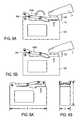
- FIGs. 6A and 6B show side and end views, respectively, of apparatus 100 in a storage configuration.
- upper arm assembly 110 is fully rotated clockwise about upper pivot axis 148 and lower arm assembly 108 is fully rotated clockwise about lower pivot axis 136.
- apparatus 100 is compact and can fit, for example, in the palm of a user's hand.
- Typical non-limiting dimensions depicted in FIGs. 6A and 6B are an X dimension of 77mm, a Y dimension of 53 mm and a Z dimension of 22 mm.
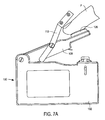
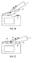
- FIGs. 7A through 7C are schematic side views depicting a sequence of steps in the operation of the apparatus 100 of FIG. 1.
- FIG. 7A depicts upper and lower arm assemblies 110 and 108 in a first position with a user's finger F contacting pressure ring 126 of lower arm assembly 108 but not applying any significant force.
- the upper and lower arm assemblies can be held in the first position by, for example, the user's finger, nominal (in comparison to F1) friction around lower pivot axis 136, or nominal (in comparison to F1) spring bias against lower arm assembly 108.
- FIG. 7B depicts lower arm assembly 108 rotating clockwise under an applied force by user's finger F.
- upper arm assembly 110 engages user's finger F (see FIG. 7B).
- upper and lower arm assemblies 108 and 110 reach a second position depicted in FIG. 7C.
- upper compression surface 144 and pressure ring 126 cooperate to exert a compressive force on user's finger F.
- the compressive force applied to is the sum of the forces applied by upper compression surface 144 and the predetermined user's force and is typically in the range of, for example, about 9N to 18N.
- the compressive force applied by compression surface 144 is greater than or equal to the predetermined force applied by user's finger F (i.e., F1).
- F2 need not be greater than F 1 in order to provide benefits as described herein.
- Fc the total compressive force
- F1 the predetermined force applied by user's finger
- F2 need not be greater than F 1 in order to provide benefits as described herein.
- about 68% of the total compressive force (Fc) is contributed by upper compression surface 144 (i.e., F2), whereas about 32% of the total force is contributed by the predetermined user's force (i.e., F1).
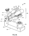
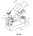
- FIGs. 8A through 8C depict various views of apparatus 200 for extracting bodily fluid according to another exemplary embodiment of the present invention.
- Apparatus 200 includes a housing 202, a lancing mechanism 204 and a clamping mechanism 206.
- Clamping mechanism 206 includes a lower arm assembly 208, an upper arm assembly 210 and a linking bar 212.
- Upper arm assembly 210 and lower arm assembly 208 are pivotally attached to housing 202 by upper pivot axis 214 and a lower pivot axis 216, respectively.
- Angle ⁇ formed between lower arm assembly 208 and housing 202 can vary from about 0 degrees to about 45 degrees during operation of apparatus 200.
- Angle ⁇ formed between upper arm assembly 210 and lower arm assembly 208 can vary from about 0 degrees to about 30 degrees during operation of apparatus 200.
- Lower arm assembly 208 includes a pressure ring 218 and a linking bar lower pivot axis 220. Lower arm assembly 208 is pivotally attached to linking bar 212 at linking bar lower pivot axis 220.
- Upper arm assembly 210 includes two cylindrically-shaped upper compression surfaces 222 and a linking bar upper pivot axis 224, as illustrated in FIG. 8B. Upper arm assembly 210 is pivotally attached to linking bar 212 at linking bar upper pivot axis 224.
- upper compression surfaces 222 are surfaces of removable cylindrical bushings 226. Furthermore compression surfaces 222 are configured to engage the top of user's finger F.
- linking bar 212 includes an adjustment screw 228 in contact with a force limiting spring 230.
- Linking bar 212 is located distally to upper pivot axis 214 and lower pivot axis 216.
- Adjustment screw 228 extends internally from the top of linking bar 212 and contacts force limiting spring 230.
- Force limiting spring 230 is also in contact with linking bar upper pivot axis 224.
- the compressive force experienced by user's finger F is limited by use of adjustment screw 228, force limiting spring 230, and linking bar upper pivot axis 224.
- Linking bar upper pivot axis 224 can reversibly and linearly move against force limiting spring 230 when the force against linking bar upper pivot axis 324 exceeds a pre-load bias set by force limiting spring 230.
- Adjustment screw 228 also enables the aforementioned pre-load bias to be adjustably set by varying the amount of compression between adjustment screw 228 and linking bar upper pivot axis 224.
- a force limiting means is optional in apparatus for extracting bodily fluid according to embodiments of the preset invention, such force limiting means can be useful for ensuring that an optimal compressive force is applied to various sized user's fingers.
- use of a force limiting means within its operative boundaries can serve to limit total compressive force to no more than, for example, 10N.
- Upper arm assembly 210 and lower arm assembly 208 can be formed of suitable rigid material including, but not limited to, aluminum, steel, polystyrene, polycarbonate and polyester. Upper arm assembly 210 can be also constructed of flexible materials including, but not limited to, polypropylene such that upper arm assembly 210 bends when the compression force against user's finger F exceeds a predetermined limit.
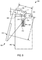
- FIG. 9 depicts an apparatus 300 for extracting bodily fluid according to yet another embodiment of the present invention.
- Apparatus 300 applies compressive force to a user's finger F such that a tourniquet effect is applied to user's finger F causing sufficient blood to pool at the dermal tissue lancing site that bodily fluid extraction is successful.
- Apparatus 300 includes a housing 302, a lancing mechanism 304 and a clamping mechanism 306.
- Housing 302 includes a means for measuring, analyzing and displaying an analyte concentration (not shown).
- Housing 302 also includes a lower compression surface 308.
- Lancing mechanism 304 is adjacent to lower compression surface 308, and includes a dermal tissue penetration member 310, a lancing spring 312 and an aperture 314 for the dermal tissue penetration member to pass through.
- Clamping mechanism is pivotally attached to housing 302 by a pivot axis 316.
- Clamping mechanism 306 includes a lever arm 318 and an inner compression surface 320.
- Inner compression surface 320 can be made of a compliant material including, for example, rubber or foam and can be contoured to adapt to a shape of user's finger F.
- the angle ⁇ formed between inner compression surface 320 and lower compression surface 308 can range from about 0 degrees to about 90 degrees during operation of apparatus 300.
- Inner compression surface 320 is in opposing relationship to lower compression surface 308 of housing 302.
- Lower compression surface 308 can be made, for example, of compliant material including rubber or foam and can be contoured to the shape of user's finger F.
- Inner compression surface 320 and lower compression surface 308 are configured to apply a compressive force on user's finger F (in a manner similar to a tourniquet), when lever arm 318 and housing 302 are squeezed together (i.e., toward one another) and lever arm 318 rotates toward housing 302, thus decreasing angle ⁇ .
- the housing and clamping mechanism are operatively connected such that a user's finger inserted between the upper compression surface and inner compression surface is engaged with a compressive force when the lever arm and housing are squeezed together (i.e., towards one another).
- the squeezing can be accomplished, for example, manually by a user's hand.
- the squeezing action is an intuitive action to the user.
- Clamping mechanism 306 applies a compressive force on a user's finger via mechanical advantage provided by the clamping mechanism's configuration.
- the mechanical advantage is the ratio of dimensions L1 and L2 (i.e., L1/L2). Therefore, the compressive force on a user's finger is beneficially greater than the force exerted on the lever arm and housing to squeeze them together.
- the mechanical advantage ratio of L1/L2 can be, for example, in the range of greater than 1 to 10.
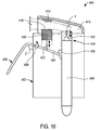
- FIG. 10 depicts an apparatus 400 for extracting bodily fluid.
- Apparatus 400 includes a housing 402, a lancing mechanism 404 and clamping mechanism 406.
- Lancing mechanism 404 includes an aperture (not shown), a trigger 409 and a dermal tissue penetration member 410.
- Clamping mechanism 406 includes an inner compression surface 414, a cavity 416, a lower compression surface 418 on a movable compression element 420, a vertical connector 422, and a lever arm 424.
- Lever arm 424 includes a pivot axis 426 and a trigger release 428.
- Inner compression surface 414 is located within cavity 416.
- Lower compression surface 418 is also located within cavity 416 in an opposing relationship with inner compression surface 414.
- Compression element 420 is attached to lever arm 424 by vertical connector 422. The angle formed between lever arm 424 and housing 402 can range from about 0 degrees to about 90 degrees during operation of apparatus 400.
- Inner compression surface 414 and lower compression surface 418 are configured to apply a compressive force on user's finger F (in a manner similar to a tourniquet), when lever arm 424 and housing 402 are squeezed together and lever arm 424 rotates toward housing 402, thus decreasing angle .
- the squeezing action is an intuitive action to the user and also serves to activate (i.e., fire) lancing mechanism 404 via trigger release 428.
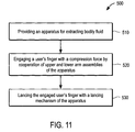
- a method 500 for extracting bodily fluid from a target site includes step 510 for providing an apparatus for extracting bodily fluid that includes (i) a housing; (ii) a lancing mechanism for lancing a target site attached to the housing and (iii) a clamping mechanism attached to the housing.
- the clamping mechanism of the apparatus includes upper and lower arm assemblies. Such apparatus have been described above (e.g., with respect to FIGs. 1 and 8A).
- a predetermined force is applied to the lower arm assembly with a user's finger such that the lower arm assembly is displaced from a first position to a second position, as set forth in step 520 of FIG. 11.
- the upper arm assembly and lower arm assembly cooperate to engage the user's finger with a compressive force that is greater than the predetermined user force (as described above with respect to, for example, FIG. 7C).
- a target site on the user's finger is lanced with the lancing mechanism, while the upper arm assembly and lower arm assembly are cooperating to engage the user's finger, whereafter the compressive force serves to extract a bodily fluid sample from the lanced target site.
Landscapes
- Health & Medical Sciences (AREA)
- Life Sciences & Earth Sciences (AREA)
- Engineering & Computer Science (AREA)
- Molecular Biology (AREA)
- Animal Behavior & Ethology (AREA)
- Veterinary Medicine (AREA)
- Biophysics (AREA)
- Pathology (AREA)
- Public Health (AREA)
- Biomedical Technology (AREA)
- Heart & Thoracic Surgery (AREA)
- Medical Informatics (AREA)
- General Health & Medical Sciences (AREA)
- Surgery (AREA)
- Physics & Mathematics (AREA)
- Hematology (AREA)
- Dermatology (AREA)
- Pain & Pain Management (AREA)
- Vascular Medicine (AREA)
- Manufacturing & Machinery (AREA)
- Measurement Of The Respiration, Hearing Ability, Form, And Blood Characteristics Of Living Organisms (AREA)
- Apparatus Associated With Microorganisms And Enzymes (AREA)
- Sampling And Sample Adjustment (AREA)
- Surgical Instruments (AREA)
Applications Claiming Priority (2)
| Application Number | Priority Date | Filing Date | Title |
|---|---|---|---|
| US10/825,899 US20050234486A1 (en) | 2004-04-16 | 2004-04-16 | Apparatus for extracting bodily fluid |
| US825899 | 2004-04-16 |
Publications (2)
| Publication Number | Publication Date |
|---|---|
| EP1586268A2 true EP1586268A2 (de) | 2005-10-19 |
| EP1586268A3 EP1586268A3 (de) | 2006-03-08 |
Family
ID=34940883
Family Applications (1)
| Application Number | Title | Priority Date | Filing Date |
|---|---|---|---|
| EP05252403A Withdrawn EP1586268A3 (de) | 2004-04-16 | 2005-04-18 | Lanzette |
Country Status (11)
| Country | Link |
|---|---|
| US (1) | US20050234486A1 (de) |
| EP (1) | EP1586268A3 (de) |
| JP (1) | JP2005305157A (de) |
| KR (1) | KR20060045771A (de) |
| CN (2) | CN1682650A (de) |
| AU (1) | AU2005201533A1 (de) |
| CA (1) | CA2504148A1 (de) |
| NO (1) | NO20051818L (de) |
| RU (1) | RU2005110994A (de) |
| SG (1) | SG116621A1 (de) |
| TW (1) | TW200603768A (de) |
Cited By (3)
| Publication number | Priority date | Publication date | Assignee | Title |
|---|---|---|---|---|
| WO2008149333A1 (en) * | 2006-07-06 | 2008-12-11 | Rapidx Ltd | Intergrated blood sampling and testing device and method of use thereof |
| WO2009022136A1 (en) | 2007-08-14 | 2009-02-19 | Owen Mumford Limited | Lancing devices |
| US9566027B2 (en) | 2007-12-25 | 2017-02-14 | Rapidx Ltd. | Device and system for blood sampling |
Families Citing this family (78)
| Publication number | Priority date | Publication date | Assignee | Title |
|---|---|---|---|---|
| US6036924A (en) | 1997-12-04 | 2000-03-14 | Hewlett-Packard Company | Cassette of lancet cartridges for sampling blood |
| US6391005B1 (en) | 1998-03-30 | 2002-05-21 | Agilent Technologies, Inc. | Apparatus and method for penetration with shaft having a sensor for sensing penetration depth |
| DE10057832C1 (de) | 2000-11-21 | 2002-02-21 | Hartmann Paul Ag | Blutanalysegerät |
| US8641644B2 (en) | 2000-11-21 | 2014-02-04 | Sanofi-Aventis Deutschland Gmbh | Blood testing apparatus having a rotatable cartridge with multiple lancing elements and testing means |
| DE60234598D1 (de) | 2001-06-12 | 2010-01-14 | Pelikan Technologies Inc | Selbstoptimierende lanzettenvorrichtung mit adaptationsmittel für zeitliche schwankungen von hauteigenschaften |
| AU2002320094A1 (en) | 2001-06-12 | 2002-12-23 | Pelikan Technologies, Inc. | Integrated blood sampling analysis system with multi-use sampling module |
| AU2002315180A1 (en) | 2001-06-12 | 2002-12-23 | Pelikan Technologies, Inc. | Electric lancet actuator |
| US9427532B2 (en) | 2001-06-12 | 2016-08-30 | Sanofi-Aventis Deutschland Gmbh | Tissue penetration device |
| US7025774B2 (en) | 2001-06-12 | 2006-04-11 | Pelikan Technologies, Inc. | Tissue penetration device |
| EP1404235A4 (de) | 2001-06-12 | 2008-08-20 | Pelikan Technologies Inc | Verfahren und gerät für eine auf einer blutentnahmekartusche integrierte lanzettenvorrichtung |
| US9226699B2 (en) | 2002-04-19 | 2016-01-05 | Sanofi-Aventis Deutschland Gmbh | Body fluid sampling module with a continuous compression tissue interface surface |
| US9795747B2 (en) | 2010-06-02 | 2017-10-24 | Sanofi-Aventis Deutschland Gmbh | Methods and apparatus for lancet actuation |
| US8337419B2 (en) | 2002-04-19 | 2012-12-25 | Sanofi-Aventis Deutschland Gmbh | Tissue penetration device |
| WO2002100252A2 (en) | 2001-06-12 | 2002-12-19 | Pelikan Technologies, Inc. | Blood sampling apparatus and method |
| US7981056B2 (en) | 2002-04-19 | 2011-07-19 | Pelikan Technologies, Inc. | Methods and apparatus for lancet actuation |
| DE60239132D1 (de) | 2001-06-12 | 2011-03-24 | Pelikan Technologies Inc | Gerät zur erhöhung der erfolgsrate im hinblick auf die durch einen fingerstich erhaltene blutausbeute |
| US7344894B2 (en) | 2001-10-16 | 2008-03-18 | Agilent Technologies, Inc. | Thermal regulation of fluidic samples within a diagnostic cartridge |
| US7198606B2 (en) | 2002-04-19 | 2007-04-03 | Pelikan Technologies, Inc. | Method and apparatus for a multi-use body fluid sampling device with analyte sensing |
| US7371247B2 (en) | 2002-04-19 | 2008-05-13 | Pelikan Technologies, Inc | Method and apparatus for penetrating tissue |
| US7297122B2 (en) | 2002-04-19 | 2007-11-20 | Pelikan Technologies, Inc. | Method and apparatus for penetrating tissue |
| US7410468B2 (en) | 2002-04-19 | 2008-08-12 | Pelikan Technologies, Inc. | Method and apparatus for penetrating tissue |
| US7374544B2 (en) | 2002-04-19 | 2008-05-20 | Pelikan Technologies, Inc. | Method and apparatus for penetrating tissue |
| US7674232B2 (en) | 2002-04-19 | 2010-03-09 | Pelikan Technologies, Inc. | Method and apparatus for penetrating tissue |
| US8579831B2 (en) | 2002-04-19 | 2013-11-12 | Sanofi-Aventis Deutschland Gmbh | Method and apparatus for penetrating tissue |
| US7901362B2 (en) | 2002-04-19 | 2011-03-08 | Pelikan Technologies, Inc. | Method and apparatus for penetrating tissue |
| US7491178B2 (en) | 2002-04-19 | 2009-02-17 | Pelikan Technologies, Inc. | Method and apparatus for penetrating tissue |
| US8784335B2 (en) | 2002-04-19 | 2014-07-22 | Sanofi-Aventis Deutschland Gmbh | Body fluid sampling device with a capacitive sensor |
| US7582099B2 (en) | 2002-04-19 | 2009-09-01 | Pelikan Technologies, Inc | Method and apparatus for penetrating tissue |
| US8221334B2 (en) | 2002-04-19 | 2012-07-17 | Sanofi-Aventis Deutschland Gmbh | Method and apparatus for penetrating tissue |
| US7648468B2 (en) | 2002-04-19 | 2010-01-19 | Pelikon Technologies, Inc. | Method and apparatus for penetrating tissue |
| US9248267B2 (en) | 2002-04-19 | 2016-02-02 | Sanofi-Aventis Deustchland Gmbh | Tissue penetration device |
| US7892183B2 (en) | 2002-04-19 | 2011-02-22 | Pelikan Technologies, Inc. | Method and apparatus for body fluid sampling and analyte sensing |
| US7909778B2 (en) | 2002-04-19 | 2011-03-22 | Pelikan Technologies, Inc. | Method and apparatus for penetrating tissue |
| US7291117B2 (en) | 2002-04-19 | 2007-11-06 | Pelikan Technologies, Inc. | Method and apparatus for penetrating tissue |
| US7563232B2 (en) | 2002-04-19 | 2009-07-21 | Pelikan Technologies, Inc. | Method and apparatus for penetrating tissue |
| US7481776B2 (en) | 2002-04-19 | 2009-01-27 | Pelikan Technologies, Inc. | Method and apparatus for penetrating tissue |
| US7976476B2 (en) | 2002-04-19 | 2011-07-12 | Pelikan Technologies, Inc. | Device and method for variable speed lancet |
| US7331931B2 (en) | 2002-04-19 | 2008-02-19 | Pelikan Technologies, Inc. | Method and apparatus for penetrating tissue |
| US7232451B2 (en) | 2002-04-19 | 2007-06-19 | Pelikan Technologies, Inc. | Method and apparatus for penetrating tissue |
| US7717863B2 (en) | 2002-04-19 | 2010-05-18 | Pelikan Technologies, Inc. | Method and apparatus for penetrating tissue |
| US7547287B2 (en) | 2002-04-19 | 2009-06-16 | Pelikan Technologies, Inc. | Method and apparatus for penetrating tissue |
| US9795334B2 (en) | 2002-04-19 | 2017-10-24 | Sanofi-Aventis Deutschland Gmbh | Method and apparatus for penetrating tissue |
| US7524293B2 (en) | 2002-04-19 | 2009-04-28 | Pelikan Technologies, Inc. | Method and apparatus for penetrating tissue |
| US7141058B2 (en) | 2002-04-19 | 2006-11-28 | Pelikan Technologies, Inc. | Method and apparatus for a body fluid sampling device using illumination |
| US9314194B2 (en) | 2002-04-19 | 2016-04-19 | Sanofi-Aventis Deutschland Gmbh | Tissue penetration device |
| US7229458B2 (en) | 2002-04-19 | 2007-06-12 | Pelikan Technologies, Inc. | Method and apparatus for penetrating tissue |
| US8267870B2 (en) | 2002-04-19 | 2012-09-18 | Sanofi-Aventis Deutschland Gmbh | Method and apparatus for body fluid sampling with hybrid actuation |
| US7175642B2 (en) | 2002-04-19 | 2007-02-13 | Pelikan Technologies, Inc. | Methods and apparatus for lancet actuation |
| US8702624B2 (en) | 2006-09-29 | 2014-04-22 | Sanofi-Aventis Deutschland Gmbh | Analyte measurement device with a single shot actuator |
| US8574895B2 (en) | 2002-12-30 | 2013-11-05 | Sanofi-Aventis Deutschland Gmbh | Method and apparatus using optical techniques to measure analyte levels |
| WO2004107964A2 (en) | 2003-06-06 | 2004-12-16 | Pelikan Technologies, Inc. | Blood harvesting device with electronic control |
| WO2006001797A1 (en) | 2004-06-14 | 2006-01-05 | Pelikan Technologies, Inc. | Low pain penetrating |
| US7604592B2 (en) | 2003-06-13 | 2009-10-20 | Pelikan Technologies, Inc. | Method and apparatus for a point of care device |
| US8282576B2 (en) | 2003-09-29 | 2012-10-09 | Sanofi-Aventis Deutschland Gmbh | Method and apparatus for an improved sample capture device |
| EP1680014A4 (de) | 2003-10-14 | 2009-01-21 | Pelikan Technologies Inc | Verfahren und gerät für eine variable anwenderschnittstelle |
| EP1706026B1 (de) | 2003-12-31 | 2017-03-01 | Sanofi-Aventis Deutschland GmbH | Verfahren und vorrichtung zur verbesserung der fluidströmung und der probennahme |
| US7822454B1 (en) | 2005-01-03 | 2010-10-26 | Pelikan Technologies, Inc. | Fluid sampling device with improved analyte detecting member configuration |
| WO2006011062A2 (en) | 2004-05-20 | 2006-02-02 | Albatros Technologies Gmbh & Co. Kg | Printable hydrogel for biosensors |
| WO2005120365A1 (en) | 2004-06-03 | 2005-12-22 | Pelikan Technologies, Inc. | Method and apparatus for a fluid sampling device |
| US8652831B2 (en) | 2004-12-30 | 2014-02-18 | Sanofi-Aventis Deutschland Gmbh | Method and apparatus for analyte measurement test time |
| US8956291B2 (en) * | 2005-02-22 | 2015-02-17 | Admetsys Corporation | Balanced physiological monitoring and treatment system |
| US20070083130A1 (en) * | 2005-09-26 | 2007-04-12 | Anne Thomson | Method for promoting bodily fluid expression from a target site |
| US8372015B2 (en) * | 2006-08-28 | 2013-02-12 | Intuity Medical, Inc. | Body fluid sampling device with pivotable catalyst member |
| TW200918021A (en) * | 2007-10-26 | 2009-05-01 | Delta Electronics Inc | Bleeding apparatus |
| WO2009126900A1 (en) | 2008-04-11 | 2009-10-15 | Pelikan Technologies, Inc. | Method and apparatus for analyte detecting device |
| WO2009145920A1 (en) | 2008-05-30 | 2009-12-03 | Intuity Medical, Inc. | Body fluid sampling device -- sampling site interface |
| WO2010011805A1 (en) * | 2008-07-24 | 2010-01-28 | Admetsys Corporation | Device and method for automatically sampling and measuring blood analytes |
| JP5218067B2 (ja) * | 2009-01-05 | 2013-06-26 | ニプロ株式会社 | 穿刺補助器具 |
| US9375169B2 (en) | 2009-01-30 | 2016-06-28 | Sanofi-Aventis Deutschland Gmbh | Cam drive for managing disposable penetrating member actions with a single motor and motor and control system |
| US8965476B2 (en) | 2010-04-16 | 2015-02-24 | Sanofi-Aventis Deutschland Gmbh | Tissue penetration device |
| EP2745778B1 (de) | 2010-06-24 | 2018-10-03 | Rapidx Ltd. | Vorrichtung zur Blutabnahme |
| DE102012112882B4 (de) * | 2012-12-21 | 2017-06-08 | Gerresheimer Regensburg Gmbh | Stechhilfe zur Gewinnung von Körperflüssigkeitsproben |
| JP7092747B2 (ja) | 2016-08-24 | 2022-06-28 | ベクトン・ディキンソン・アンド・カンパニー | 血液の付着流のための装置 |
| CN107582071A (zh) * | 2017-07-27 | 2018-01-16 | 珠海柯诺医疗科技有限公司 | 一种电动的手指夹持装置 |
| JP6905953B2 (ja) * | 2018-05-15 | 2021-07-21 | 富士フイルム株式会社 | 血液検体案内器具、及び血液検査キット |
| JP7437671B2 (ja) * | 2019-10-24 | 2024-02-26 | ホーユー株式会社 | エアゾール容器用吐出具 |
| WO2021128154A1 (zh) * | 2019-12-26 | 2021-07-01 | 郝云玲 | 一种末梢血采集装置 |
| US20240081703A1 (en) * | 2022-09-13 | 2024-03-14 | Health Made Easy | Blood collection devices and methods |
Family Cites Families (16)
| Publication number | Priority date | Publication date | Assignee | Title |
|---|---|---|---|---|
| CH500707A (fr) * | 1968-07-26 | 1970-12-31 | Micromedic Systems Inc | Dispositif pour effectuer une prise de sang percutanée et digitale |
| US3633584A (en) * | 1969-06-10 | 1972-01-11 | Research Corp | Method and means for marking animals for identification |
| US4157086A (en) * | 1975-10-13 | 1979-06-05 | Farmitalia Carlo Erba S.P.A. | Apparatus for providing skin cuts to a predetermined measure |
| US5163442A (en) * | 1991-07-30 | 1992-11-17 | Harry Ono | Finger tip blood collector |
| US5324302A (en) * | 1992-10-13 | 1994-06-28 | Sherwood Medical Company | Lancet with locking cover |
| AU4967197A (en) * | 1996-11-25 | 1998-06-22 | Ecodevice Laboratory Co., Ltd. | Photocatalyst having visible light activity and uses thereof |
| US5893870A (en) * | 1997-07-21 | 1999-04-13 | Actilife L.L.C. | Device and method for restricting venous flow for improved blood sampling |
| US6197040B1 (en) * | 1999-02-23 | 2001-03-06 | Lifescan, Inc. | Lancing device having a releasable connector |
| US6048353A (en) * | 1999-03-04 | 2000-04-11 | L. Vad Technology, Inc. | Trephine device for locating and cutting a cylindrical or reverse tapered aperture in flexible material |
| US6283982B1 (en) * | 1999-10-19 | 2001-09-04 | Facet Technologies, Inc. | Lancing device and method of sample collection |
| US6743749B2 (en) * | 2000-01-27 | 2004-06-01 | Kabushiki Kaisha Toyota Chuo Kenkyusho | Photocatalyst |
| DE10026170A1 (de) * | 2000-05-26 | 2001-12-06 | Roche Diagnostics Gmbh | System zur Entnahme von Körperflüssigkeit |
| DE10026172A1 (de) * | 2000-05-26 | 2001-11-29 | Roche Diagnostics Gmbh | System zur Entnahme von Körperflüssigkeit |
| IL153295A0 (en) * | 2000-06-09 | 2003-07-06 | Diabetes Diagnostics Inc | Cap for a lancing device |
| AU2002221075A1 (en) * | 2000-12-06 | 2002-06-18 | Kabushiki Kaisya Advance | Facilitated body fluid inspection unit |
| US20030211619A1 (en) * | 2002-05-09 | 2003-11-13 | Lorin Olson | Continuous strip of fluid sampling and testing devices and methods of making, packaging and using the same |
-
2004
- 2004-04-16 US US10/825,899 patent/US20050234486A1/en not_active Abandoned
-
2005
- 2005-04-12 AU AU2005201533A patent/AU2005201533A1/en not_active Abandoned
- 2005-04-14 RU RU2005110994/14A patent/RU2005110994A/ru not_active Application Discontinuation
- 2005-04-14 NO NO20051818A patent/NO20051818L/no not_active Application Discontinuation
- 2005-04-14 CA CA002504148A patent/CA2504148A1/en not_active Abandoned
- 2005-04-15 KR KR1020050031504A patent/KR20060045771A/ko not_active Withdrawn
- 2005-04-15 TW TW094111921A patent/TW200603768A/zh unknown
- 2005-04-15 SG SG200502329A patent/SG116621A1/en unknown
- 2005-04-15 JP JP2005118606A patent/JP2005305157A/ja active Pending
- 2005-04-16 CN CNA2005100741387A patent/CN1682650A/zh active Pending
- 2005-04-16 CN CNA2005100717547A patent/CN1701757A/zh active Pending
- 2005-04-18 EP EP05252403A patent/EP1586268A3/de not_active Withdrawn
Cited By (4)
| Publication number | Priority date | Publication date | Assignee | Title |
|---|---|---|---|---|
| WO2008149333A1 (en) * | 2006-07-06 | 2008-12-11 | Rapidx Ltd | Intergrated blood sampling and testing device and method of use thereof |
| WO2009022136A1 (en) | 2007-08-14 | 2009-02-19 | Owen Mumford Limited | Lancing devices |
| US9078604B2 (en) | 2007-08-14 | 2015-07-14 | Owen Mumford Limited | Lancing devices |
| US9566027B2 (en) | 2007-12-25 | 2017-02-14 | Rapidx Ltd. | Device and system for blood sampling |
Also Published As
| Publication number | Publication date |
|---|---|
| SG116621A1 (en) | 2005-11-28 |
| NO20051818L (no) | 2005-10-17 |
| KR20060045771A (ko) | 2006-05-17 |
| JP2005305157A (ja) | 2005-11-04 |
| RU2005110994A (ru) | 2006-10-20 |
| AU2005201533A1 (en) | 2005-11-03 |
| CN1701757A (zh) | 2005-11-30 |
| NO20051818D0 (no) | 2005-04-14 |
| EP1586268A3 (de) | 2006-03-08 |
| CN1682650A (zh) | 2005-10-19 |
| CA2504148A1 (en) | 2005-10-16 |
| US20050234486A1 (en) | 2005-10-20 |
| TW200603768A (en) | 2006-02-01 |
Similar Documents
| Publication | Publication Date | Title |
|---|---|---|
| EP1586268A2 (de) | Lanzette | |
| US20070073187A1 (en) | Analyte monitoring system with a device for promoting bodily fluid expression from a target site | |
| EP1560517B1 (de) | Kappe für lanzette | |
| JP4180056B2 (ja) | 体液採取システム | |
| US20060247670A1 (en) | Lancing device with automatic lancet release | |
| US10251589B2 (en) | Method and system for withdrawing blood | |
| RU2269954C2 (ru) | Колпачок для ланцетного устройства для прокалывания дермальной ткани (варианты), колпачок для ланцетного устройства для прокалывания кончика пальца, колпачок для ланцетного устройства для прокалывания криволинейной дермальной ткани, ланцетное устройство для прокалывания дермальной ткани | |
| US20070093864A1 (en) | Method for lancing a dermal tissue target site | |
| US20070093863A1 (en) | Cap for a dermal tissue lancing device | |
| US20100249653A1 (en) | Devices and methods for expression of bodily fluids from an incision | |
| EP1586270A3 (de) | Kappe für eine Lanzette | |
| US20050277972A1 (en) | Expression pad | |
| EP1399066A1 (de) | Vorrichtungen und verfahren zum ausdrücken von körperflüssigkeiten aus einem einschnitt | |
| HK1081828A (en) | Lancet | |
| MXPA05007009A (es) | Aparato para extraer fluido corporal. | |
| HK1076701B (en) | Cap for a dermal tissue lancing device |
Legal Events
| Date | Code | Title | Description |
|---|---|---|---|
| PUAI | Public reference made under article 153(3) epc to a published international application that has entered the european phase |
Free format text: ORIGINAL CODE: 0009012 |
|
| AK | Designated contracting states |
Kind code of ref document: A2 Designated state(s): AT BE BG CH CY CZ DE DK EE ES FI FR GB GR HU IE IS IT LI LT LU MC NL PL PT RO SE SI SK TR |
|
| AX | Request for extension of the european patent |
Extension state: AL BA HR LV MK YU |
|
| PUAL | Search report despatched |
Free format text: ORIGINAL CODE: 0009013 |
|
| AK | Designated contracting states |
Kind code of ref document: A3 Designated state(s): AT BE BG CH CY CZ DE DK EE ES FI FR GB GR HU IE IS IT LI LT LU MC NL PL PT RO SE SI SK TR |
|
| AX | Request for extension of the european patent |
Extension state: AL BA HR LV MK YU |
|
| REG | Reference to a national code |
Ref country code: HK Ref legal event code: DE Ref document number: 1081828 Country of ref document: HK |
|
| 17P | Request for examination filed |
Effective date: 20060818 |
|
| AKX | Designation fees paid |
Designated state(s): AT BE BG CH CY CZ DE DK EE ES FI FR GB GR HU IE IS IT LI LT LU MC NL PL PT RO SE SI SK TR |
|
| STAA | Information on the status of an ep patent application or granted ep patent |
Free format text: STATUS: THE APPLICATION IS DEEMED TO BE WITHDRAWN |
|
| 18D | Application deemed to be withdrawn |
Effective date: 20081101 |
|
| REG | Reference to a national code |
Ref country code: HK Ref legal event code: WD Ref document number: 1081828 Country of ref document: HK |