EP1585205A2 - Steuergerät für einen Motor und Verfahren zur Steuerung des Motors - Google Patents
Steuergerät für einen Motor und Verfahren zur Steuerung des Motors Download PDFInfo
- Publication number
- EP1585205A2 EP1585205A2 EP05252215A EP05252215A EP1585205A2 EP 1585205 A2 EP1585205 A2 EP 1585205A2 EP 05252215 A EP05252215 A EP 05252215A EP 05252215 A EP05252215 A EP 05252215A EP 1585205 A2 EP1585205 A2 EP 1585205A2
- Authority
- EP
- European Patent Office
- Prior art keywords
- motor
- pump
- power
- fluid
- act
- Prior art date
- Legal status (The legal status is an assumption and is not a legal conclusion. Google has not performed a legal analysis and makes no representation as to the accuracy of the status listed.)
- Granted
Links
Images


Classifications
-
- F—MECHANICAL ENGINEERING; LIGHTING; HEATING; WEAPONS; BLASTING
- F04—POSITIVE - DISPLACEMENT MACHINES FOR LIQUIDS; PUMPS FOR LIQUIDS OR ELASTIC FLUIDS
- F04D—NON-POSITIVE-DISPLACEMENT PUMPS
- F04D15/00—Control, e.g. regulation, of pumps, pumping installations or systems
- F04D15/0066—Control, e.g. regulation, of pumps, pumping installations or systems by changing the speed, e.g. of the driving engine
-
- F—MECHANICAL ENGINEERING; LIGHTING; HEATING; WEAPONS; BLASTING
- F04—POSITIVE - DISPLACEMENT MACHINES FOR LIQUIDS; PUMPS FOR LIQUIDS OR ELASTIC FLUIDS
- F04D—NON-POSITIVE-DISPLACEMENT PUMPS
- F04D15/00—Control, e.g. regulation, of pumps, pumping installations or systems
- F04D15/02—Stopping of pumps, or operating valves, on occurrence of unwanted conditions
- F04D15/0209—Stopping of pumps, or operating valves, on occurrence of unwanted conditions responsive to a condition of the working fluid
- F04D15/0218—Stopping of pumps, or operating valves, on occurrence of unwanted conditions responsive to a condition of the working fluid the condition being a liquid level or a lack of liquid supply
- F04D15/0236—Lack of liquid level being detected by analysing the parameters of the electric drive, e.g. current or power consumption
Definitions
- the invention relates to a controller for a motor, and particularly, a controller for a motor operating a pump.
- the main drain can become obstructed with an object, such as a towel or pool toy.
- an object such as a towel or pool toy.
- suction force of the pump is applied to the obstruction and the object sticks to the drain. This is called suction entrapment.
- the object substantially covers the drain (such as a towel covering the drain)
- water is pumped out of the drain side of the pump.
- Mechanical entrapment occurs when an object, such as a towel or pool toy, gets tangled in the drain cover. Mechanical entrapment may also effect the operation of the pump.
- SVRS Safety Vacuum Release Systems
- Most SVRS use hydraulic release valves that are plumbed into the suction side of the pump.
- the valve is designed to release (open to the atmosphere) if the vacuum (or pressure) inside the drain pipe exceeds a set threshold, thus releasing the obstruction.
- These valves can be very effective at releasing the suction developed under these circumstances.
- they have several technical problems that have limited their use. The first problem is that when the valve releases, the pump loses its water supply and the pump can still be damaged.
- the second problem is that the release valve typically needs to be mechanically adjusted for each pool. Even if properly adjusted, the valve can be prone to nuisance trips.
- the third problem is that the valve needs to be plumbed properly into the suction side of the pump. This makes installation difficult for the average homeowner.
- the invention provides a controller for a motor that monitors motor input power and/or pump inlet side pressure (also referred to as pump inlet side vacuum). This monitoring helps to determine if a drain obstruction has taken place. If the drain or plumbing is substantially restricted on the suction side of the pump, the pressure on that side of the pump increases. At the same time, because the pump is no longer pumping fluid, input power to the motor drops. Either of these conditions may be considered a fault and the motor is powered down. It is also envisioned that should the pool filter become plugged, the pump input power also drops and the motor is powered down as well.
- motor input power and/or pump inlet side pressure also referred to as pump inlet side vacuum
- Fig. 1 schematically represents a jetted-spa 100 incorporating the invention.
- the invention is not limited to the jetted-spa 100 and can be used in other jetted-fluid systems (e.g., pools, whirlpools, jetted-tubs, etc.). It is also envisioned that the invention can be used in other applications (e.g., fluid-pumping applications).
- the spa 100 includes a vessel 105.
- the vessel 105 is a hollow container such as a tub, pool, tank, or vat that holds a load.
- the load includes a fluid, such as chlorinated water, and may include one or more occupants or items.
- the spa further includes a fluid-movement system 110 coupled to the vessel 105.
- the fluid-movement system 110 includes a drain 115, a pumping apparatus 120 having an inlet 125 coupled to the drain and an outlet 130, and a return 135 coupled to the outlet 130 of the pumping apparatus 120.
- the pumping apparatus 120 includes a pump 140, a motor 145 coupled to the pump 140, and a controller 150 for controlling the motor 145.
- the pump 140 is a centrifugal pump and the motor 145 is an induction motor (e.g., capacitor-start, capacitor-run induction motor; split-phase induction motor; three-phase induction motor; etc.).
- the invention is not limited to this type of pump or motor.
- a brushless, direct current (DC) motor may be used in a different pumping application.
- a jetted-fluid system can include multiple drains, multiple returns, or even multiple fluid movement systems.
- the vessel 105 holds a fluid.
- the pump 140 causes the fluid to move from the drain 115, through the pump 140, and jet into the vessel 105.
- This pumping operation occurs when the controller 150 controllably provides a power to the motor 145, resulting in a mechanical movement by the motor 145.
- the coupling of the motor 145 e.g., a direct coupling or an indirect coupling via a linkage system
- the operation of the controller 150 can be via an operator interface, which may be as simple as an ON switch.
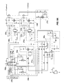
- Fig. 2 is a block diagram of a first construction of the controller 150, and Figs. 3A and 3B are electrical schematics of the controller 150. As shown in Fig. 2, the controller 150 is electrically connected to a power source 155 and the motor 145.
- the controller 150 includes a power supply 160.
- the power supply 160 includes resistors R46 and R56; capacitors C13, C14, C16, C18, C19, and C20; diodes D10 and D11; zener diodes D12 and D13; power supply controller U7; regulator U6; and optical switch U8.
- the power supply 160 receives power from the power source 155 and provides the proper DC voltage (e.g., -5 VDC and -12 VDC) for operating the controller 150.
- the controller 150 monitors motor input power and pump inlet side pressure to determine if a drain obstruction has taken place. If the drain 115 or plumbing is plugged on the suction side of the pump 140, the pressure on that side of the pump 140 increases. At the same time, because the pump 140 is no longer pumping water, input power to the motor 145 drops. If either of these conditions occur, the controller 150 declares a fault, the motor 145 powers down, and a fault indicator lights.
- a voltage sense and average circuit 165, a current sense and average circuit 170, a line voltage sense circuit 175, a triac voltage sense circuit 180, and the microcontroller 185 perform the monitoring of the input power.
- One example voltage sense and average circuit 165 is shown in Fig. 3A.
- the voltage sense and average circuit 165 includes resistors R34, R41, and R42; diode D9; capacitor C10; and operational amplifier U4A.
- the voltage sense and average circuit rectifies the voltage from the power source 155 and then performs a DC average of the rectified voltage. The DC average is then fed to the microcontroller 185.
- the current sense and average circuit 170 includes transformer T1 and resistor R45, which act as a current sensor that senses the current applied to the motor.
- the current sense and average circuit also includes resistors R25, R26, R27, R28, and R33; diodes D7 and D8; capacitor C9; and operational amplifiers U4C and U4D, which rectify and average the value representing the sensed current.
- the resultant scaling of the current sense and average circuit 170 can be a negative five to zero volt value corresponding to a zero to twenty-five amp RMS value.
- the resulting DC average is then fed to the microcontroller 185.
- the line voltage sense circuit 175 includes resistors R23, R24, and R32; diode D5; zener diode D6; transistor Q6; and NAND gate U2B.
- the line voltage sense circuit 175 includes a zero-crossing detector that generates a pulse signal.
- the pulse signal includes pulses that are generated each time the line voltage crosses zero volts,
- the triac voltage sense circuit 180 includes resistors R1, R5, and R6; diode D2; zener diode D1; transistor Q1; and NAND gate U2A.
- the triac voltage sense circuit includes a zero-crossing detector that generates a pulse signal.
- the pulse signal includes pulses that are generated each time the motor current crosses zero.
- microcontroller 185 that can be used with the invention is a Motorola brand microcontroller, model no. MC68HC908QY4CP.
- the microcontroller 185 includes a processor and a memory,
- the memory includes software instructions that are read, interpreted, and executed by the processor to manipulate data or signals.
- the memory also includes data storage memory.
- the microcontroller 185 can include other circuitry (e.g., an analog-to-digital converter) necessary for operating the microcontroller 185.
- the microcontroller 185 receives inputs (signals or data), executes software instructions to analyze the inputs, and generates outputs (signals or data) based on the analyses.
- microcontroller 185 is shown and described, the invention can be implemented with other devices, including a variety of integrated circuits (e.g., an application-specific-integrated circuit), programmable devices, and/or discrete devices, as would be apparent to one of ordinary skill in the art. Additionally, it is envisioned that the microcontroller 185 or similar circuitry can be distributed among multiple microcontrollers 185 or similar circuitry. It is also envisioned that the microcontroller 185 or similar circuitry can perform the function of some of the other circuitry described (e.g., circuitry 165-180) above for the controller 150.
- the microcontroller 185 in some constructions, can receive a sensed voltage and/or sensed current and determine an averaged voltage, an averaged current, the zero-crossings of the sensed voltage, and/or the zero crossings of the sensed current.
- the microcontroller 185 receives the signals representing the average voltage applied to the motor 145, the average current through the motor 145, the zero crossings of the motor voltage, and the zero crossings of the motor current. Based on the zero crossings, the microcontroller 185 can determine a power factor. The power factor can be calculated using known mathematical equations or by using a lookup table based on the mathematical equations. The microcontroller 185 can then calculate a power with the averaged voltage, the averaged current, and the power factor as is known. As will be discussed later, the microcontroller 185 compares the calculated power with a power calibration value to determine whether a fault condition (e.g., due to an obstruction) is present.
- a fault condition e.g., due to an obstruction
- a pressure (or vacuum) sensor circuit 190 and the microcontroller 185 monitor the pump inlet side pressure.
- One example pressure sensor circuit 190 is shown in Fig. 3A.
- the pressure sensor circuit 190 includes resistors R16, R43, R44, R47, and R48; capacitors C8, C12, C15, and C17; zener diode D4, piezoresistive sensor U9, and operational amplifier U4-B.
- the piezoresistive sensor U9 is plumbed into the suction side of the pump 140.
- the pressure sensor circuit 190 and microcontroller 185 translate and amplify the signal generated by the piezoresistive sensor U9 into a value representing inlet pressure.
- the microcontroller 185 compares the resulting pressure value with a pressure calibration value to determine whether a fault condition (e.g., due to an obstruction) is present.
- the calibrating of the controller 150 occurs when the user activates a calibrate switch 195.
- One example calibrate switch 195 is shown in Fig. 3A.
- the calibrate switch 195 includes resistor R18 and Hall effect switch U10.
- the switch 195 When a magnet passes Hall effect switch U10, the switch 195 generates a signal provided to the microcontroller 185.
- the microcontroller 185 Upon receiving the signal, the microcontroller 185 stores a pressure calibration value for the pressure sensor by acquiring the current pressure and stores a power calibration value for the motor by calculating the present power.
- the controller 150 controllably provides power to the motor 145.
- the controller 150 includes a retriggerable pulse generator circuit 200.
- the retriggerable pulse generator circuit 200 includes resistor R7, capacitor C1, and pulse generator U1A, and outputs a value to NAND gate U2D if the retriggerable pulse generator circuit 200 receives a signal having a pulse frequency greater than a set frequency determined by resistor R7 and capacitor C1.
- the NAND gate U2D also receives a signal from power-up delay circuit 205, which prevents nuisance triggering of the relay on startup.
- the output of the NAND gate U2D is provided to relay driver circuit 210,
- the relay driver circuit 210 shown in Fig. 3A includes resistors R19, R20, R21, and R22; capacitor C7; diode D3; and switches Q5 and Q4.
- the relay driver circuit 210 controls relay K1.
- the microcontroller 185 also provides an output to triac driver circuit 215, which controls triac Q2.
- the triac driver circuit 215 includes resistors R12, R13, and R14; capacitor C11; and switch Q3.
- relay K1 needs to close and triac Q2 needs to be triggered on.
- the controller 150 also includes a thermoswitch S1 for monitoring the triac heat sink, a power supply monitor 220 for monitoring the voltages produced by the power supply 160, and a plurality of LEDs DS1, DS2, and DS3 for providing information to the user.
- a green LED DS1 indicates power is applied to the controller 150
- a red LED DS2 indicates a fault has occurred
- a third LED DS3 is a heartbeat LED to indicate the microcontroller 185 is functioning.
- other interfaces can be used for providing information to the operator.
- the system 110 may have to draw air out of the suction side plumbing and get the fluid flowing smoothly.
- This "priming" period usually lasts only a few seconds, but could last a minute or more if there is a lot of air in the system.
- the water flow, suction side pressure, and motor input power remain relatively constant. It is during this normal running period that the circuit is effective at detecting an abnormal event.
- the microcontroller 185 includes a startup-lockout feature that keeps the monitor from detecting the abnormal conditions during the priming period.
- the spa operator can calibrate the controller 150 to the current spa running conditions.
- the calibration values are stored in the microcontroller 185 memory, and will be used as the basis for monitoring the spa 100. If for some reason the operating conditions of the spa change, the controller 150 can be re-calibrated by the operator. If at any time during normal operations, however, the suction side pressure increases substantially (e.g., 12%) over the pressure calibration value, or the motor input power drops (e.g., 12%) under the power calibration value, the pump will be powered down and a fault indicator is lit.
- the controller 150 measures motor input power, and not just motor power factor or input current. Some motors have electrical characteristics such that power factor remains constant while the motor is unloaded. Other motors have an electrical characteristic such that current remains relatively constant when the pump is unloaded. However, the input power drops on pump systems when the drain is plugged, and water flow is impeded.
- the voltage sense and average circuit 165 generates a value representing the average power line voltage and the current sense and average circuit 170 generates a value representing the average motor current.
- Motor power factor is derived from the difference between power line zero crossing events and triac zero crossing events.
- the line voltage sense circuit 175 provides a signal representing the power line zero crossings.
- the triac zero crossings occur at the zero crossings of the motor current.
- the triac voltage sense circuit 180 provides a signal representing the triac zero crossings.
- the time difference from the zero crossing events is used to look up the motor power factor from a table stored in the microcontroller 185. This data is then used to calculate the motor input power using equation e1.
- V avg * I avg * PF Motor_Input_Power
- the calculated motor_input_power is then compared to the calibrated value to determine whether a fault has occurred. If a fault has occurred, the motor is powered down and the fault is lit.
- Another aspect of the controller 150 is a "soft-start" feature.
- a typical pump motor 145 When a typical pump motor 145 is switched on, it quickly accelerates up to full speed. The sudden acceleration creates a vacuum surge on the inlet side of the pump 140, and a pressure surge on the discharge side of the pump 140. The vacuum surge can nuisance trip the hydraulic release valves of the spa 100.
- the pressure surge on the outlet can also create a water hammer that is hard on the plumbing and especially hard on the filter (if present).
- the soft-start feature slowly increases the voltage applied to the motor over a time period (e.g., two seconds). By gradually increasing the voltage, the motor accelerates more smoothly, and the pressure/vacuum spike in the plumbing is avoided.
- controller 150 Another aspect of the controller 150 is the use of redundant sensing systems. By looking at both pump inlet side pressure and motor input power, if a failure were to occur in either one, the remaining sensor would still shut down the system 110.
- Redundancy is also used for the power switches that switch power to the motor. Both a relay and a triac are used in series to do this function. This way, a failure of either component will still leave one switch to turn off the motor 145. As an additional safety feature, the proper operation of both switches is checked by the microcontroller 185 every time the motor is powered on.
- the triac Q2 can be used as the primary switching element, thus avoiding a lot of wear and tear on the relay contacts.
- arcing may occur, which eventually erodes the contact surfaces of the relay K1.
- the relay K1 will no longer make reliable contact or even stick in a closed position.
- the triac Q2 as the primary switch, the relay contacts can be closed before the triac completes the circuit to the motor 145.
- the triac Q2 can terminate conduction of current before the relay opens. This way there is no arcing of the relay contacts.
- the triac Q2 has no wear-out mechanism, so it can do this switching function repeatedly.
- controller 150 Another aspect of the controller 150 is the use of several monitoring functions to verify that all the circuits are working as intended. These functions can include verifying whether input voltage is in a reasonable range, verifying whether motor current is in a reasonable range, and verifying whether suction side pressure is in a reasonable range. For example, if motor current exceeds 135% of its calibrated value, the motor may be considered over-loaded and is powered down.
- the controller 150 also monitors the power supply 160 and the temperature of the triac heat sink. If either is out of proper range, the controller 185 can power down the motor 145 and declare a fault.
- the controller 150 also monitors the line voltage sense and triac voltage sense circuits 175 and 180, respectively. If zero crossing pulses are received from either of these circuits at a frequency less than a defined time (e.g., every 80 milliseconds), the motor powers down.
- the microcontroller 185 must provide pulses at a frequency greater than a set frequency (determined by the time constant of resistor R7 and C1) to close the relay K1. If the pulse generator U1A is not triggered at the proper frequency, the relay K1 opens and the motor powers down.
- the invention provides, among other things, a controller for a motor operating a pump. While numerous aspects of the controller 150 were discussed above, not all of the aspects and features discussed above are required for the invention. For example, the controller 150 can be modified to monitor only motor input power or suction side pressure. Additionally, other aspects and features can be added to the controller 150 shown in the figures. For example, some of the features discussed below for controller 150a can be added to the controller 150.
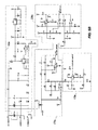
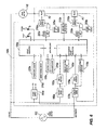
- Fig. 4 is a block diagram of a second construction of the controller 150a, and Figs. 5A and 5B are an electrical schematic of the controller 150a. As shown in Fig. 4, the controller 150a is electrically connected to a power source 155 and the motor 145.
- the controller 150a includes a power supply 160a.
- the power supply 160a includes resistors R54, R56 and R76; capacitors C16, C18, C20, C21, C22, C23 and C25; diodes D8, D10 and D11; zener diodes D6, D7 and D9; power supply controller U11; regulator U9; inductors L1 and L2, surge suppressors MOV1 and MOV2, and optical switch U10.
- the power supply 160a receives power from the power source 155 and provides the proper DC voltage (e.g., +5 VDC and +12 VDC) for operating the controller 150a.
- the controller 150a monitors motor input power to determine if a drain obstruction has taken place. Similar to the earlier disclosed construction, if the drain 115 or plumbing is plugged on the suction side of the pump 140, the pump 140 will no longer be pumping water, and input power to the motor 145 drops. If this condition occurs, the controller 150a declares a fault, the motor 145 powers down, and a fault indicator lights.
- a voltage sense and average circuit 165a, a current sense and average circuit 170a, and the microcontroller 185a perform the monitoring of the input power.
- One example voltage sense and average circuit 165a is shown in Fig. 5A.
- the voltage sense and average circuit 165a includes resistors R2, R31, R34, R35, R39, R59, R62, and R63; diodes D2 and D12; capacitor C14; and operational amplifiers U5C and U5D.
- the voltage sense and average circuit 165a rectifies the voltage from the power source 155 and then performs a DC average of the rectified voltage.
- the DC average is then fed to the microcontroller 185a.
- the voltage sense and average circuit 165a further includes resistors R22, R23, R27, R28, R30, and R36; capacitor C27; and comparator U7A; which provide the sign of the voltage waveform (i.e., acts as a zero-crossing detector) to the microcontroller 185a.
- the current sense and average circuit 170a includes transformer T1 and resistor R53, which act as a current sensor that senses the current applied to the motor 145.
- the current sense and average circuit 170a also includes resistors R18, R20, R21, R40, R43, and R57; diodes D3 and D4; capacitor C8; and operational amplifiers U5A and U5B, which rectify and average the value representing the sensed current.
- the resultant scaling of the current sense and average circuit 170a can be a positive five to zero volt value corresponding to a zero to twenty-five amp RMS value.
- the resulting DC average is then fed to the microcontroller 185a.
- the current sense and average circuit 170a further includes resistors R24, R25, R26, R29, R41, and R44; capacitor C11; and comparator U7B; which provide the sign of the current waveform (i.e., acts as a zero-crossing detector) to microcontroller 185a.
- microcontroller 185a that can be used with the invention is a Motorola brand microcontroller, model no. MC68HC908QY4CP. Similar to what was discussed for the earlier construction, the microcontroller 185a includes a processor and a memory. The memory includes software instructions that are read, interpreted, and executed by the processor to manipulate data or signals. The memory also includes data storage memory. The microcontroller 185a can include other circuitry (e.g., an analog-to-digital converter) necessary for operating the microcontroller 185a and/or can perform the function of some of the other circuitry described above for the controller 150a. In general, the microcontroller 185a receives inputs (signals or data), executes software instructions to analyze the inputs, and generates outputs (signals or data) based on the analyses.
- the microcontroller 185a receives the signals representing the average voltage applied to the motor 145, the average current through the motor 145, the zero crossings of the motor voltage, and the zero crossings of the motor current, Based on the zero crossings, the microcontroller 185a can determine a power factor and a power as was described earlier. The microcontroller 185a can then compare the calculated power with a power calibration value to determine whether a fault condition (e.g., due to an obstruction) is present.
- a fault condition e.g., due to an obstruction
- the calibrating of the controller 150a occurs when the user activates a calibrate switch 195a.
- a calibrate switch 195a is shown in Fig. 5A, which is similar to the calibrate switch 195 shown in Fig. 3A.
- a calibration fob needs to be held near the switch 195a when the controller 150a receives an initial power. After removing the magnet and cycling power, the controller 150a goes through priming and enters an automatic calibration mode (discussed below).
- the controller 150a controllably provides power to the motor 145.
- the controller 150a includes a retriggerable pulse generator circuit 200a.
- the retriggerable pulse generator circuit 200a includes resistors R15 and R16, capacitors C2 and C6, and pulse generators U3A and U3B, and outputs a value to the relay driver circuit 210a if the retriggerable pulse generator circuit 200a receives a signal having a pulse frequency greater than a set frequency determined by resistors R15 and R16, and capacitors C2 and C6.
- the retriggerable pulse generators U3A and U3B also receive a signal from power-up delay circuit 205a, which prevents nuisance triggering of the relays on startup.
- the relay driver circuits 210a shown in Fig. 5A includes resistors R1, R3, R47, and R52; diodes D1 and D5; and switches Q1 and Q2.
- the relay driver circuits 210a control relays K1 and K2. In order for current to flow to the motor, both relays K1 and K2 need to "close".
- the controller 150a further includes two voltage detectors 212a and 214a.
- the first voltage detector 212a includes resistors R71, R72, and R73; capacitor C26; diode D14; and switch Q4, The first voltage detector 212a detects when voltage is present across relay K1, and verifies that the relays are functioning properly before allowing the motor to be energized.
- the second voltage detector 214a includes resistors R66, R69, and R70; capacitor C9; diode D 13; and switch Q3.
- the second voltage detector 214a senses if a two speed motor is being operated in high or low speed mode.
- the motor input power trip values are set according to what speed the motor is being operated. It is also envisioned that the controller 150a can be used with a single speed motor without the second voltage detector 214a (e.g., controller 150b is shown in Fig. 6).
- the controller 150a also includes an ambient thermal sensor circuit 216a for monitoring the operating temperature of the controller 150a, a power supply monitor 220a for monitoring the voltages produced by the power supply 160a, and a plurality of LEDs DS1 and DS3 for providing information to the user.
- a green LED DS2 indicates power is applied to the controller 150a
- a red LED DS3 indicates a fault has occurred.
- other interfaces can be used for providing information to the operator.
- the controller 150a further includes a clean mode switch 218a, which includes switch U4 and resistor R10.
- the clean mode switch can be depressed by an operator (e.g., a maintenance person) to deactivate the power monitoring function described herein for a time period (e.g., 30 minutes so that maintenance person can clean the vessel 105). After the time period, the controller 150a returns to normal operation.
- the system 110 may have to prime (discussed above) the suction side plumbing and get the fluid flowing smoothly (referred to as "the normal running period"). It is during the normal running period that the circuit is most effective at detecting an abnormal event.
- the controller 150a can include instructions to perform an automatic calibration after priming upon a system power-up.
- the calibration values are stored in the microcontroller 185 memory, and will be used as the basis for monitoring the spa 100. If for some reason the operating conditions of the spa change, the controller 150a can be re-calibrated by the operator. If at any time during normal operation, however, the motor input power varies from the power calibration value (e.g., varies from a 12.5% window around the power calibration value), the pump motor 145 will be powered down and a fault indicator is lit.
- the controller 150a measures motor input power, and not just motor power factor or input current. However, it is envisioned that the controllers 150 or 150a can be modified to monitor other motor parameters (e.g., only motor current, only motor power factor, or motor speed). But motor input power is the preferred motor parameter for controller 150a for determining whether the water is impeded. Also, it is envisioned that the controller 150a can be modified to monitor other parameters (e.g., suction side pressure) of the system 110.
- the microcontroller 185a monitors the motor input power for an over power condition in addition to an under power condition.
- the monitoring of an over power condition helps reduce the chance that controller 150a was incorrectly calibrated, and/or also helps detect when the pump is over loaded (e.g., the pump is moving too much fluid).
- the voltage sense and average circuit 165a generates a value representing the averaged power line voltage and the current sense and average circuit 170a generates a value representing the averaged motor current.
- Motor power factor is derived from the timing difference between the sign of the voltage signal and the sign of the current signal. This time difference is used to look up the motor power factor from a table stored in the microcontroller 185a. The averaged power line voltage, the averaged motor current, and the motor power factor are then used to calculate the motor input power using equation e1 as was discussed earlier. The calculated motor input power is then compared to the calibrated value to determine whether a fault has occurred. If a fault has occurred, the motor is powered down and the fault indicator is lit.
- Redundancy is also used for the power switches of the controller 150a.
- Two relays K1 and K2 are used in series to do this function. This way, a failure of either component will still leave one switch to turn off the motor 145.
- the proper operation of both relays is checked by the microcontroller 185a every time the motor 145 is powered on via the relay voltage detector circuit 212a.
- controller 150a Another aspect of the controller 150a is the use of several monitoring functions to verify that all the circuits are working as intended. These functions can include verifying whether input voltage is in a reasonable range (i.e. 85 to 135 VAC, or 175 to 255 VAC), and verifying whether motor current is in a reasonable range (5% to 95% of range). Also, if motor current exceeds 135% of its calibrated value, the motor may be considered over-loaded and is powered down.
- the controller 150a also monitors the power supply 160a and the ambient temperature of the circuitry of the controller 150a. If either is out of proper range, the controller 150a will power down the motor 145 and declare a fault. The controller 150a also monitors the sign of the power line voltage and the sign of the motor current. If the zero crossing pulses resulting from this monitoring is at a frequency less than a defined time (e.g., every 30 milliseconds), then the motor powers down.
- a defined time e.g., every 30 milliseconds
- the microcontroller 185a provides pulses at a frequency greater than a set frequency (determined by the retriggerable pulse generator circuits) to close the relays K1 and K2. If the pulse generators U3A and U3B are not triggered at the proper frequency, the relays K1 and K2 open and the motor powers down.
- the microcontroller 185a includes an automatic reset feature, which may help to recognize a nuisance trip (e.g., due to an air bubble in the fluid-movement system 110).
- the microcontroller 185a after detecting a fault and powering down the motor, waits a time period (e.g., a minute), resets, and attempts to start the pump. If the controller 150a cannot successfully start the pump after a defined number of tries (e.g., five), the microcontroller 185a locks until powered down and restarted.
- the microcontroller 185a can further be programmed to clear the fault history if the pump runs normally for a time period.
- the microcontroller 185a can include a startup-lockout feature that keeps the monitor from indicating abnormal conditions during a priming period, thereby preventing unnecessary nuisance trips.
- the microcontroller 185a initiates a lockout-condition upon startup, but monitors motor input power upon startup, If the pump 140 is priming, the input is typically low. Once the input power enters a monitoring window (e.g., within 12.5% above or below the power calibration value) and stays there for a time period (e.g., two seconds), the microcontroller 185 ceases the lockout condition and enters normal operation even though the pump may not be fully primed. This feature allows the controller 150a to perform normal monitoring as soon as possible, while reducing the likelihood of nuisance tripping during the priming period.
- a complete priming event may last two-to-three minutes after the controller 150a is powered up.
- the suction force on the inlet 115 is sufficient for entrapment.
- the just-described method of operation for ceasing the lockout condition provides a greater efficiency of protection than a timed, startup lockout.
- controller 150a While numerous aspects of the controller 150a were discussed above, not all of the aspects and features discussed above are required for the invention. Additionally, other aspects and features can be added to the controller 150a shown in the figures.
Landscapes
- Engineering & Computer Science (AREA)
- Mechanical Engineering (AREA)
- General Engineering & Computer Science (AREA)
- Control Of Positive-Displacement Pumps (AREA)
- Control Of Non-Positive-Displacement Pumps (AREA)
Applications Claiming Priority (2)
| Application Number | Priority Date | Filing Date | Title |
|---|---|---|---|
| US56106304P | 2004-04-09 | 2004-04-09 | |
| US561063P | 2004-04-09 |
Publications (3)
| Publication Number | Publication Date |
|---|---|
| EP1585205A2 true EP1585205A2 (de) | 2005-10-12 |
| EP1585205A3 EP1585205A3 (de) | 2008-12-03 |
| EP1585205B1 EP1585205B1 (de) | 2017-12-06 |
Family
ID=34911036
Family Applications (1)
| Application Number | Title | Priority Date | Filing Date |
|---|---|---|---|
| EP05252215.8A Expired - Lifetime EP1585205B1 (de) | 2004-04-09 | 2005-04-08 | Pumpenaggregat und Verfahren zur Entdeckung einer Verstopfung in einem Pumpenaggregat |
Country Status (2)
| Country | Link |
|---|---|
| US (3) | US8177520B2 (de) |
| EP (1) | EP1585205B1 (de) |
Cited By (26)
| Publication number | Priority date | Publication date | Assignee | Title |
|---|---|---|---|---|
| US20090288407A1 (en) * | 2006-10-13 | 2009-11-26 | Bartos Ronald P | Controller for a motor and a method of controlling the motor |
| EP2151580A1 (de) * | 2008-08-05 | 2010-02-10 | Ksb S.A.S | Betriebssteuerung eines Motorpumpenaggregats |
| EP2151579A1 (de) | 2008-08-05 | 2010-02-10 | Ksb S.A.S | Fehlerüberwachung und Betriebssteuerung eines Motorpumpenaggregats |
| WO2010013116A3 (en) * | 2008-07-28 | 2010-11-18 | Eaton Corporation | Electronic control for a rotary fluid device |
| US20110002792A1 (en) * | 2004-04-09 | 2011-01-06 | Bartos Ronald P | Controller for a motor and a method of controlling the motor |
| EP1911977A3 (de) * | 2006-10-13 | 2011-01-19 | A.O. Smith Corporation | Steuerung für einen Motor und Verfahren zur Motorsteuerung |
| CN101994704A (zh) * | 2010-10-26 | 2011-03-30 | 浙江佳力科技股份有限公司 | 化工流程智能泵及其控制方法 |
| EP1816352A3 (de) * | 2006-02-07 | 2011-08-17 | A.O. Smith Corporation | Steuerung für einen Motor und Verfahren zur Motorsteuerung |
| US8177520B2 (en) | 2004-04-09 | 2012-05-15 | Regal Beloit Epc Inc. | Controller for a motor and a method of controlling the motor |
| US8354809B2 (en) | 2008-10-01 | 2013-01-15 | Regal Beloit Epc Inc. | Controller for a motor and a method of controlling the motor |
| US8360736B2 (en) | 2006-10-13 | 2013-01-29 | Regal Beloit Epc Inc. | Controller for a motor and a method of controlling the motor |
| CN103591032A (zh) * | 2013-10-23 | 2014-02-19 | 江苏大学 | 一种叶片泵流动不稳定性程度的监测方法和装置 |
| US9328727B2 (en) | 2003-12-08 | 2016-05-03 | Pentair Water Pool And Spa, Inc. | Pump controller system and method |
| US9404500B2 (en) | 2004-08-26 | 2016-08-02 | Pentair Water Pool And Spa, Inc. | Control algorithm of variable speed pumping system |
| US9551344B2 (en) | 2004-08-26 | 2017-01-24 | Pentair Water Pool And Spa, Inc. | Anti-entrapment and anti-dead head function |
| US9556874B2 (en) | 2009-06-09 | 2017-01-31 | Pentair Flow Technologies, Llc | Method of controlling a pump and motor |
| US9568005B2 (en) | 2010-12-08 | 2017-02-14 | Pentair Water Pool And Spa, Inc. | Discharge vacuum relief valve for safety vacuum release system |
| US9726184B2 (en) | 2008-10-06 | 2017-08-08 | Pentair Water Pool And Spa, Inc. | Safety vacuum release system |
| US9777733B2 (en) | 2004-08-26 | 2017-10-03 | Pentair Water Pool And Spa, Inc. | Flow control |
| US9885360B2 (en) | 2012-10-25 | 2018-02-06 | Pentair Flow Technologies, Llc | Battery backup sump pump systems and methods |
| US9932984B2 (en) | 2004-08-26 | 2018-04-03 | Pentair Water Pool And Spa, Inc. | Pumping system with power optimization |
| US10240606B2 (en) | 2004-08-26 | 2019-03-26 | Pentair Water Pool And Spa, Inc. | Pumping system with two way communication |
| US10465676B2 (en) | 2011-11-01 | 2019-11-05 | Pentair Water Pool And Spa, Inc. | Flow locking system and method |
| US10731655B2 (en) | 2004-08-26 | 2020-08-04 | Pentair Water Pool And Spa, Inc. | Priming protection |
| US10871001B2 (en) | 2004-08-26 | 2020-12-22 | Pentair Water Pool And Spa, Inc. | Filter loading |
| US10947981B2 (en) | 2004-08-26 | 2021-03-16 | Pentair Water Pool And Spa, Inc. | Variable speed pumping system and method |
Families Citing this family (46)
| Publication number | Priority date | Publication date | Assignee | Title |
|---|---|---|---|---|
| US8337166B2 (en) | 2001-11-26 | 2012-12-25 | Shurflo, Llc | Pump and pump control circuit apparatus and method |
| US8281425B2 (en) * | 2004-11-01 | 2012-10-09 | Cohen Joseph D | Load sensor safety vacuum release system |
| AU2012258346B2 (en) * | 2006-12-11 | 2015-07-02 | Danfoss Low Power Drives | Flow control |
| DE102007050662A1 (de) * | 2007-10-24 | 2009-04-30 | Continental Teves Ag & Co. Ohg | Verfahren und Vorrichtung zur Kalibrierung oder Diagnose einer Kraftfahrzeugbremsanlage mit einer getaktet betriebenen Pumpe |
| US8436559B2 (en) | 2009-06-09 | 2013-05-07 | Sta-Rite Industries, Llc | System and method for motor drive control pad and drive terminals |
| US8564233B2 (en) | 2009-06-09 | 2013-10-22 | Sta-Rite Industries, Llc | Safety system and method for pump and motor |
| US10030647B2 (en) | 2010-02-25 | 2018-07-24 | Hayward Industries, Inc. | Universal mount for a variable speed pump drive user interface |
| WO2011106557A1 (en) * | 2010-02-25 | 2011-09-01 | Hayward Industries, Inc. | Pump controller with external device control capability |
| US20120219428A1 (en) * | 2011-02-25 | 2012-08-30 | Christopher Cantolino | Pool timer |
| EP2788110B1 (de) | 2011-12-08 | 2018-10-17 | Pentair Water Pool and Spa, Inc. | Aquakulturanlage und verfahren zum betreiben einer pumpe dafür |
| ITCO20110069A1 (it) * | 2011-12-20 | 2013-06-21 | Nuovo Pignone Spa | Disposizione di prova per uno stadio di un compressore centrifugo |
| WO2013188741A2 (en) * | 2012-06-14 | 2013-12-19 | Flow Control Llc. | Technique for preventing air lock through stuttered starting and air release slit for pumps |
| US8798825B1 (en) | 2012-07-06 | 2014-08-05 | Richard L. Hartman | Wakeboat hull control systems and methods |
| WO2014152926A1 (en) | 2013-03-14 | 2014-09-25 | Pentair Water Pool And Spa, Inc. | Carbon dioxide control system for aquaculture |
| EP3954352B1 (de) | 2013-03-15 | 2024-08-21 | Hayward Industries, Inc. | Steuerungssystem für modulares schwimmbad/spa |
| WO2014145661A1 (en) | 2013-03-15 | 2014-09-18 | Pentair Water Pool And Spa, Inc. | Dissolved oxygen control system for aquaculture |
| CN105736404B (zh) * | 2014-12-09 | 2018-03-13 | 中国石油天然气股份有限公司 | 潜油电泵井的控制远传柜 |
| KR101637771B1 (ko) * | 2014-12-11 | 2016-07-08 | 현대자동차주식회사 | 전자식 진공 펌프의 제어 방법 |
| US10527043B2 (en) | 2015-03-27 | 2020-01-07 | Regal Beloit America, Inc. | Motor, controller and associated method |
| US9856869B2 (en) | 2015-04-14 | 2018-01-02 | Regal Beloit America, Inc. | Motor, controller and associated method |
| US9951780B2 (en) | 2015-04-14 | 2018-04-24 | Regal Beloit America, Inc. | Motor, controller and associated method |
| US9970434B2 (en) | 2015-05-17 | 2018-05-15 | Regal Beloit America, Inc. | Motor, controller and associated method |
| US11720085B2 (en) | 2016-01-22 | 2023-08-08 | Hayward Industries, Inc. | Systems and methods for providing network connectivity and remote monitoring, optimization, and control of pool/spa equipment |
| US10363197B2 (en) | 2016-01-22 | 2019-07-30 | Hayward Industries, Inc. | Systems and methods for providing network connectivity and remote monitoring, optimization, and control of pool/spa equipment |
| EP3484638A4 (de) * | 2016-09-07 | 2019-10-23 | Sunrise Global Marketing | Hochdruckreiniger und verfahren zum betrieb eines hochdruckreinigers mit elektronischer druck-/flusssteuerung und anzeige |
| US10864971B2 (en) | 2016-09-09 | 2020-12-15 | Richard L. Hartman | Wakeboat hydraulic manifold assemblies and methods |
| CA2978824C (en) | 2016-09-09 | 2021-09-07 | Richard L. Hartman | Wakeboat engine powered ballasting apparatus and methods |
| US11505289B2 (en) | 2016-09-09 | 2022-11-22 | Richard L. Hartman | Wakeboat bilge measurement assemblies and methods |
| US10329004B2 (en) | 2016-09-09 | 2019-06-25 | Richard L. Hartman | Wakeboat ballast measurement assemblies and methods |
| US11254395B2 (en) | 2016-09-09 | 2022-02-22 | Richard L. Hartman | Aquatic invasive species control apparatuses and methods for watercraft |
| US10611440B2 (en) | 2016-09-09 | 2020-04-07 | Richard L. Hartman | Boat propulsion assemblies and methods |
| US10611439B2 (en) | 2016-09-09 | 2020-04-07 | Richard L. Hartman | Wakeboat engine hydraulic pump mounting apparatus and methods |
| US11014635B2 (en) | 2016-09-09 | 2021-05-25 | Richard L. Hartman | Power source assemblies and methods for distributing power aboard a watercraft |
| US10829186B2 (en) | 2016-09-09 | 2020-11-10 | Richard L. Hartman | Wakeboat ballast measurement assemblies and methods |
| US11014634B2 (en) | 2016-09-09 | 2021-05-25 | Richard L. Hartman | Hydraulic power sources for watercraft and methods for providing hydraulic power aboard a watercraft |
| US10435122B2 (en) | 2016-09-09 | 2019-10-08 | Richard L. Hartman | Wakeboat propulsion apparatuses and methods |
| US12600441B2 (en) | 2016-09-09 | 2026-04-14 | Richard L. Hartman | Thruster conduit assemblies |
| US10718337B2 (en) | 2016-09-22 | 2020-07-21 | Hayward Industries, Inc. | Self-priming dedicated water feature pump |
| US9977433B1 (en) | 2017-05-05 | 2018-05-22 | Hayward Industries, Inc. | Automatic pool cleaner traction correction |
| US10515742B1 (en) * | 2018-05-31 | 2019-12-24 | General Electric Company | Power cable and system for delivering electrical power |
| HUE060607T2 (hu) * | 2019-03-20 | 2023-04-28 | Xylem Europe Gmbh | Eljárás folyadékszállításra szolgáló berendezés mûködése során falslevegõ-szívás jelentkezésének észlelésére |
| CN111794952B (zh) * | 2020-08-03 | 2025-06-17 | 深圳市帝拓电子有限公司 | 一种真空泵控制电路及真空泵控制方法 |
| WO2022155798A1 (en) | 2021-01-19 | 2022-07-28 | Alibaba Group Holding Limited | Memory priming and initialization systems and methods |
| US12419483B2 (en) | 2022-05-13 | 2025-09-23 | Haier Us Appliance Solutions, Inc. | Appliance and method for operation using fluid level detection by pattern recognition of motor current |
| US12606279B2 (en) | 2022-12-22 | 2026-04-21 | Skier's Choice | Wakeboat hull control systems and methods |
| CN118327947B (zh) * | 2024-05-08 | 2025-03-28 | 浙江大元泵业股份有限公司 | 一种智能水泵控制方法 |
Citations (2)
| Publication number | Priority date | Publication date | Assignee | Title |
|---|---|---|---|---|
| US4703387A (en) | 1986-05-22 | 1987-10-27 | Franklin Electric Co., Inc. | Electric motor underload protection system |
| US5577890A (en) | 1994-03-01 | 1996-11-26 | Trilogy Controls, Inc. | Solid state pump control and protection system |
Family Cites Families (162)
| Publication number | Priority date | Publication date | Assignee | Title |
|---|---|---|---|---|
| US1061919A (en) | 1912-09-19 | 1913-05-13 | Clifford G Miller | Magnetic switch. |
| US2767277A (en) | 1952-12-04 | 1956-10-16 | James F Wirth | Control system for power operated fluid pumps |
| US3191935A (en) | 1962-07-02 | 1965-06-29 | Brunswick Corp | Pin detection means including electrically conductive and magnetically responsive circuit closing particles |
| US3558910A (en) | 1968-07-19 | 1971-01-26 | Motorola Inc | Relay circuits employing a triac to prevent arcing |
| US3617839A (en) | 1969-12-01 | 1971-11-02 | Lear Siegler Inc | Brushless motor and inverter |
| US3781925A (en) | 1971-11-26 | 1974-01-01 | G Curtis | Pool water temperature control |
| US3838597A (en) | 1971-12-28 | 1974-10-01 | Mobil Oil Corp | Method and apparatus for monitoring well pumping units |
| US3953777A (en) | 1973-02-12 | 1976-04-27 | Delta-X Corporation | Control circuit for shutting off the electrical power to a liquid well pump |
| US3963375A (en) | 1974-03-12 | 1976-06-15 | Curtis George C | Time delayed shut-down circuit for recirculation pump |
| US4021700A (en) | 1975-06-04 | 1977-05-03 | Borg-Warner Corporation | Digital logic control system for three-phase submersible pump motor |
| US4185187A (en) | 1977-08-17 | 1980-01-22 | Rogers David H | Electric water heating apparatus |
| US4168413A (en) | 1978-03-13 | 1979-09-18 | Halpine Joseph C | Piston detector switch |
| DE2946049A1 (de) | 1979-11-15 | 1981-05-27 | Hoechst Ag, 6000 Frankfurt | Verfahren zum regeln des durchflusses von kreiselpumpen |
| US4319712A (en) | 1980-04-28 | 1982-03-16 | Ofer Bar | Energy utilization reduction devices |
| US4371315A (en) | 1980-09-02 | 1983-02-01 | International Telephone And Telegraph Corporation | Pressure booster system with low-flow shut-down control |
| US4473338A (en) | 1980-09-15 | 1984-09-25 | Garmong Victor H | Controlled well pump and method of analyzing well production |
| US4370098A (en) | 1980-10-20 | 1983-01-25 | Esco Manufacturing Company | Method and apparatus for monitoring and controlling on line dynamic operating conditions |
| US4428434A (en) | 1981-06-19 | 1984-01-31 | Gelaude Jonathon L | Automatic fire protection system |
| JPS5843615A (ja) | 1981-09-10 | 1983-03-14 | Kureha Chem Ind Co Ltd | コンデンサ−出力回路 |
| US4420787A (en) | 1981-12-03 | 1983-12-13 | Spring Valley Associates Inc. | Water pump protector |
| US4449260A (en) | 1982-09-01 | 1984-05-22 | Whitaker Brackston T | Swimming pool cleaning method and apparatus |
| JPS5967826A (ja) * | 1982-10-06 | 1984-04-17 | 株式会社椿本チエイン | 電動機械の過負荷・軽負荷保護装置 |
| US4505643A (en) | 1983-03-18 | 1985-03-19 | North Coast Systems, Inc. | Liquid pump control |
| US4676914A (en) | 1983-03-18 | 1987-06-30 | North Coast Systems, Inc. | Microprocessor based pump controller for backwashable filter |
| GB8315154D0 (en) * | 1983-06-02 | 1983-07-06 | Ideal Standard | Pump protection system |
| US4864287A (en) | 1983-07-11 | 1989-09-05 | Square D Company | Apparatus and method for calibrating a motor monitor by reading and storing a desired value of the power factor |
| US4998097A (en) | 1983-07-11 | 1991-03-05 | Square D Company | Mechanically operated pressure switch having solid state components |
| US4678404A (en) * | 1983-10-28 | 1987-07-07 | Hughes Tool Company | Low volume variable rpm submersible well pump |
| FR2554633B1 (fr) | 1983-11-04 | 1986-12-05 | Savener System | Dispositif de commande d'alimentation intermittente d'appareils electriques notamment d'une chambre d'hotel |
| DE3402120A1 (de) | 1984-01-23 | 1985-07-25 | Rheinhütte vorm. Ludwig Beck GmbH & Co, 6200 Wiesbaden | Verfahren und vorrichtung zur regelung verschiedener betriebsparameter bei pumpen und verdichtern |
| US4514989A (en) | 1984-05-14 | 1985-05-07 | Carrier Corporation | Method and control system for protecting an electric motor driven compressor in a refrigeration system |
| US4581900A (en) | 1984-12-24 | 1986-04-15 | Borg-Warner Corporation | Method and apparatus for detecting surge in centrifugal compressors driven by electric motors |
| US5324170A (en) | 1984-12-31 | 1994-06-28 | Rule Industries, Inc. | Pump control apparatus and method |
| US4647825A (en) * | 1985-02-25 | 1987-03-03 | Square D Company | Up-to-speed enable for jam under load and phase loss |
| DE3542370C2 (de) | 1985-11-30 | 2003-06-05 | Wilo Gmbh | Verfahren zum Regeln der Förderhöhe einer Pumpe |
| US4697464A (en) | 1986-04-16 | 1987-10-06 | Martin Thomas E | Pressure washer systems analyzer |
| US4695779A (en) | 1986-05-19 | 1987-09-22 | Sargent Oil Well Equipment Company Of Dover Resources, Incorporated | Motor protection system and process |
| USRE33874E (en) | 1986-05-22 | 1992-04-07 | Franklin Electric Co., Inc. | Electric motor load sensing system |
| US4828626A (en) | 1986-08-15 | 1989-05-09 | Crystal Pools, Inc. | Cleaning system for swimming pools and the like |
| US4896101A (en) | 1986-12-03 | 1990-01-23 | Cobb Harold R W | Method for monitoring, recording, and evaluating valve operating trends |
| US4837656A (en) | 1987-02-27 | 1989-06-06 | Barnes Austen Bernard | Malfunction detector |
| US4839571A (en) | 1987-03-17 | 1989-06-13 | Barber-Greene Company | Safety back-up for metering pump control |
| US6965815B1 (en) | 1987-05-27 | 2005-11-15 | Bilboa Instruments, Inc. | Spa control system |
| US5550753A (en) | 1987-05-27 | 1996-08-27 | Irving C. Siegel | Microcomputer SPA control system |
| US5361215A (en) | 1987-05-27 | 1994-11-01 | Siege Industries, Inc. | Spa control system |
| US4781525A (en) | 1987-07-17 | 1988-11-01 | Minnesota Mining And Manufacturing Company | Flow measurement system |
| US4841404A (en) * | 1987-10-07 | 1989-06-20 | Spring Valley Associates, Inc. | Pump and electric motor protector |
| US4885655A (en) | 1987-10-07 | 1989-12-05 | Spring Valley Associates, Inc. | Water pump protector unit |
| US4996646A (en) * | 1988-03-31 | 1991-02-26 | Square D Company | Microprocessor-controlled circuit breaker and system |
| US5079784A (en) | 1989-02-03 | 1992-01-14 | Hydr-O-Dynamic Systems, Inc. | Hydro-massage tub control system |
| JPH078877Y2 (ja) | 1989-03-07 | 1995-03-06 | 株式会社荏原製作所 | 水中ポンプ用制御装置 |
| US4971522A (en) | 1989-05-11 | 1990-11-20 | Butlin Duncan M | Control system and method for AC motor driven cyclic load |
| US5347664A (en) | 1990-06-20 | 1994-09-20 | Kdi American Products, Inc. | Suction fitting with pump control device |
| US5167041A (en) | 1990-06-20 | 1992-12-01 | Kdi American Products, Inc. | Suction fitting with pump control device |
| US5255148A (en) | 1990-08-24 | 1993-10-19 | Pacific Scientific Company | Autoranging faulted circuit indicator |
| US5172089A (en) | 1991-06-14 | 1992-12-15 | Wright Jane F | Pool pump fail safe switch |
| US5234286A (en) | 1992-01-08 | 1993-08-10 | Kenneth Wagner | Underground water reservoir |
| US5930092A (en) | 1992-01-17 | 1999-07-27 | Load Controls, Incorporated | Power monitoring |
| US5473497A (en) * | 1993-02-05 | 1995-12-05 | Franklin Electric Co., Inc. | Electronic motor load sensing device |
| US5632468A (en) | 1993-02-24 | 1997-05-27 | Aquatec Water Systems, Inc. | Control circuit for solenoid valve |
| US5422014A (en) | 1993-03-18 | 1995-06-06 | Allen; Ross R. | Automatic chemical monitor and control system |
| CA2120277A1 (en) | 1993-04-05 | 1994-10-06 | Ronald W. Holling | Over temperature condition sensing method and apparatus for a domestic appliance |
| US5548854A (en) | 1993-08-16 | 1996-08-27 | Kohler Co. | Hydro-massage tub control system |
| US5545012A (en) | 1993-10-04 | 1996-08-13 | Rule Industries, Inc. | Soft-start pump control system |
| US5959534A (en) | 1993-10-29 | 1999-09-28 | Splash Industries, Inc. | Swimming pool alarm |
| US5624237A (en) | 1994-03-29 | 1997-04-29 | Prescott; Russell E. | Pump overload control assembly |
| US6768279B1 (en) | 1994-05-27 | 2004-07-27 | Emerson Electric Co. | Reprogrammable motor drive and control therefore |
| US5570481A (en) | 1994-11-09 | 1996-11-05 | Vico Products Manufacturing Co., Inc. | Suction-actuated control system for whirlpool bath/spa installations |
| US5574346A (en) * | 1995-05-15 | 1996-11-12 | Delco Electronics Corporation | On and off state fault detection circuit for a multi-phase brushed or brushless DC motor |
| CA2163137A1 (en) | 1995-11-17 | 1997-05-18 | Ben B. Wolodko | Method and apparatus for controlling downhole rotary pump used in production of oil wells |
| US5727933A (en) | 1995-12-20 | 1998-03-17 | Hale Fire Pump Company | Pump and flow sensor combination |
| US6059536A (en) | 1996-01-22 | 2000-05-09 | O.I.A. Llc | Emergency shutdown system for a water-circulating pump |
| FR2744572B1 (fr) * | 1996-02-02 | 1998-03-27 | Schneider Electric Sa | Relais electronique |
| US5601413A (en) | 1996-02-23 | 1997-02-11 | Great Plains Industries, Inc. | Automatic low fluid shut-off method for a pumping system |
| US6074180A (en) | 1996-05-03 | 2000-06-13 | Medquest Products, Inc. | Hybrid magnetically suspended and rotated centrifugal pumping apparatus and method |
| US5971712A (en) | 1996-05-22 | 1999-10-26 | Ingersoll-Rand Company | Method for detecting the occurrence of surge in a centrifugal compressor |
| US6199224B1 (en) | 1996-05-29 | 2001-03-13 | Vico Products Mfg., Co. | Cleaning system for hydromassage baths |
| US5633540A (en) | 1996-06-25 | 1997-05-27 | Lutron Electronics Co., Inc. | Surge-resistant relay switching circuit |
| US5833437A (en) | 1996-07-02 | 1998-11-10 | Shurflo Pump Manufacturing Co. | Bilge pump |
| US5883489A (en) | 1996-09-27 | 1999-03-16 | General Electric Company | High speed deep well pump for residential use |
| US6092992A (en) | 1996-10-24 | 2000-07-25 | Imblum; Gregory G. | System and method for pump control and fault detection |
| US5690476A (en) | 1996-10-25 | 1997-11-25 | Miller; Bernard J. | Safety device for avoiding entrapment at a water reservoir drain |
| DE19804175A1 (de) | 1997-02-04 | 1998-09-03 | Nissan Motor | Vorrichtung und Verfahren zur Feststellung des Vorhandenseins oder der Abwesenheit eines Fremdkörpers oder dergleichen, der in einem motorbetriebenen Öffnungs/Schließmechanismus gefangen ist |
| US5947700A (en) | 1997-07-28 | 1999-09-07 | Mckain; Paul C. | Fluid vacuum safety device for fluid transfer systems in swimming pools |
| US6171073B1 (en) | 1997-07-28 | 2001-01-09 | Mckain Paul C. | Fluid vacuum safety device for fluid transfer and circulation systems |
| US6468052B2 (en) | 1997-07-28 | 2002-10-22 | Robert M. Downey | Vacuum relief device for fluid transfer and circulation systems |
| DE19736079A1 (de) | 1997-08-20 | 1999-02-25 | Uwe Unterwasser Electric Gmbh | Einrichtung zur Erzeugung einer Wasserströmung in einem Schwimmbecken |
| US6045333A (en) | 1997-12-01 | 2000-04-04 | Camco International, Inc. | Method and apparatus for controlling a submergible pumping system |
| US6137418A (en) * | 1998-03-05 | 2000-10-24 | Eaton Corporation | Single channel apparatus for on-line monitoring of three-phase AC motor stator electrical faults |
| US6616413B2 (en) | 1998-03-20 | 2003-09-09 | James C. Humpheries | Automatic optimizing pump and sensor system |
| US6342841B1 (en) | 1998-04-10 | 2002-01-29 | O.I.A. Llc | Influent blockage detection system |
| US5907281A (en) | 1998-05-05 | 1999-05-25 | Johnson Engineering Corporation | Swimmer location monitor |
| JPH11348794A (ja) | 1998-06-08 | 1999-12-21 | Koyo Seiko Co Ltd | パワーステアリング装置 |
| US6238188B1 (en) | 1998-08-17 | 2001-05-29 | Carrier Corporation | Compressor control at voltage and frequency extremes of power supply |
| US6282370B1 (en) | 1998-09-03 | 2001-08-28 | Balboa Instruments, Inc. | Control system for bathers |
| JP2000179339A (ja) | 1998-12-18 | 2000-06-27 | Aisin Seiki Co Ltd | 冷却水循環装置 |
| US6696676B1 (en) | 1999-03-30 | 2004-02-24 | General Electric Company | Voltage compensation in combination oven using radiant and microwave energy |
| TW470815B (en) | 1999-04-30 | 2002-01-01 | Arumo Technos Kk | Method and apparatus for controlling a vacuum pump |
| DE19931961A1 (de) | 1999-07-12 | 2001-02-01 | Danfoss As | Verfahren zur Regelung einer Fördergröße einer Pumpe |
| US6468042B2 (en) | 1999-07-12 | 2002-10-22 | Danfoss Drives A/S | Method for regulating a delivery variable of a pump |
| US6227808B1 (en) | 1999-07-15 | 2001-05-08 | Hydroair A Unit Of Itt Industries | Spa pressure sensing system capable of entrapment detection |
| US6157304A (en) | 1999-09-01 | 2000-12-05 | Bennett; Michelle S. | Pool alarm system including motion detectors and a drain blockage sensor |
| JP3660168B2 (ja) | 1999-09-03 | 2005-06-15 | 矢崎総業株式会社 | 電源供給装置 |
| US6481973B1 (en) | 1999-10-27 | 2002-11-19 | Little Giant Pump Company | Method of operating variable-speed submersible pump unit |
| FR2801645B1 (fr) * | 1999-11-30 | 2005-09-23 | Matsushita Electric Industrial Co Ltd | Dispositif d'entrainement d'un compresseur lineaire, support et ensemble d'informations |
| US6501629B1 (en) | 2000-10-26 | 2002-12-31 | Tecumseh Products Company | Hermetic refrigeration compressor motor protector |
| US6638023B2 (en) | 2001-01-05 | 2003-10-28 | Little Giant Pump Company | Method and system for adjusting operating parameters of computer controlled pumps |
| US6534947B2 (en) | 2001-01-12 | 2003-03-18 | Sta-Rite Industries, Inc. | Pump controller |
| DE10116339B4 (de) | 2001-04-02 | 2005-05-12 | Danfoss Drives A/S | Verfahren zum Betreiben einer Zentrifugalpumpe |
| US6543940B2 (en) | 2001-04-05 | 2003-04-08 | Max Chu | Fiber converter faceplate outlet |
| US7046163B2 (en) * | 2001-05-24 | 2006-05-16 | Watkins Manufacturing Corporation | Two-way RF remote control |
| US6534940B2 (en) * | 2001-06-18 | 2003-03-18 | Smart Marine Systems, Llc | Marine macerator pump control module |
| US6504338B1 (en) | 2001-07-12 | 2003-01-07 | Varidigm Corporation | Constant CFM control algorithm for an air moving system utilizing a centrifugal blower driven by an induction motor |
| US6676831B2 (en) | 2001-08-17 | 2004-01-13 | Michael Lawrence Wolfe | Modular integrated multifunction pool safety controller (MIMPSC) |
| US6625519B2 (en) | 2001-10-01 | 2003-09-23 | Veeder-Root Company Inc. | Pump controller for submersible turbine pumps |
| US6623245B2 (en) | 2001-11-26 | 2003-09-23 | Shurflo Pump Manufacturing Company, Inc. | Pump and pump control circuit apparatus and method |
| US7083392B2 (en) | 2001-11-26 | 2006-08-01 | Shurflo Pump Manufacturing Company, Inc. | Pump and pump control circuit apparatus and method |
| US20030106147A1 (en) | 2001-12-10 | 2003-06-12 | Cohen Joseph D. | Propulsion-Release Safety Vacuum Release System |
| JP2003176788A (ja) | 2001-12-10 | 2003-06-27 | Matsushita Electric Ind Co Ltd | リニアコンプレッサの駆動装置 |
| US6636135B1 (en) | 2002-06-07 | 2003-10-21 | Christopher J. Vetter | Reed switch control for a garbage disposal |
| US7168924B2 (en) | 2002-09-27 | 2007-01-30 | Unico, Inc. | Rod pump control system including parameter estimator |
| US6806677B2 (en) | 2002-10-11 | 2004-10-19 | Gerard Kelly | Automatic control switch for an electric motor |
| US6933693B2 (en) | 2002-11-08 | 2005-08-23 | Eaton Corporation | Method and apparatus of detecting disturbances in a centrifugal pump |
| US6709240B1 (en) | 2002-11-13 | 2004-03-23 | Eaton Corporation | Method and apparatus of detecting low flow/cavitation in a centrifugal pump |
| US6875961B1 (en) | 2003-03-06 | 2005-04-05 | Thornbury Investments, Inc. | Method and means for controlling electrical distribution |
| US6895608B2 (en) | 2003-04-16 | 2005-05-24 | Paramount Leisure Industries, Inc. | Hydraulic suction fuse for swimming pools |
| JP3924548B2 (ja) | 2003-04-22 | 2007-06-06 | 株式会社東海理化電機製作所 | ウィンドウガラスの挟み込み有無検出装置 |
| US6998807B2 (en) | 2003-04-25 | 2006-02-14 | Itt Manufacturing Enterprises, Inc. | Active sensing and switching device |
| US6941785B2 (en) | 2003-05-13 | 2005-09-13 | Ut-Battelle, Llc | Electric fuel pump condition monitor system using electrical signature analysis |
| US6732387B1 (en) | 2003-06-05 | 2004-05-11 | Belvedere Usa Corporation | Automated pedicure system |
| US6989649B2 (en) | 2003-07-09 | 2006-01-24 | A. O. Smith Corporation | Switch assembly, electric machine having the switch assembly, and method of controlling the same |
| US7163380B2 (en) | 2003-07-29 | 2007-01-16 | Tokyo Electron Limited | Control of fluid flow in the processing of an object with a fluid |
| US8540493B2 (en) | 2003-12-08 | 2013-09-24 | Sta-Rite Industries, Llc | Pump control system and method |
| US20050133088A1 (en) | 2003-12-19 | 2005-06-23 | Zorba, Agio & Bologeorges, L.P. | Solar-powered water features with submersible solar cells |
| US7327275B2 (en) | 2004-02-02 | 2008-02-05 | Gecko Alliance Group Inc. | Bathing system controller having abnormal operational condition identification capabilities |
| US20050193485A1 (en) | 2004-03-02 | 2005-09-08 | Wolfe Michael L. | Machine for anticipatory sensing and intervention to avoid swimmer entrapment |
| US8177520B2 (en) | 2004-04-09 | 2012-05-15 | Regal Beloit Epc Inc. | Controller for a motor and a method of controlling the motor |
| US20110002792A1 (en) | 2004-04-09 | 2011-01-06 | Bartos Ronald P | Controller for a motor and a method of controlling the motor |
| US8133034B2 (en) | 2004-04-09 | 2012-03-13 | Regal Beloit Epc Inc. | Controller for a motor and a method of controlling the motor |
| US20080095639A1 (en) | 2006-10-13 | 2008-04-24 | A.O. Smith Corporation | Controller for a motor and a method of controlling the motor |
| US7080508B2 (en) | 2004-05-13 | 2006-07-25 | Itt Manufacturing Enterprises, Inc. | Torque controlled pump protection with mechanical loss compensation |
| US7330779B2 (en) | 2004-06-18 | 2008-02-12 | Unico, Inc. | Method and system for improving pump efficiency and productivity under power disturbance conditions |
| US8019479B2 (en) | 2004-08-26 | 2011-09-13 | Pentair Water Pool And Spa, Inc. | Control algorithm of variable speed pumping system |
| US7845913B2 (en) | 2004-08-26 | 2010-12-07 | Pentair Water Pool And Spa, Inc. | Flow control |
| US8602745B2 (en) | 2004-08-26 | 2013-12-10 | Pentair Water Pool And Spa, Inc. | Anti-entrapment and anti-dead head function |
| US7854597B2 (en) | 2004-08-26 | 2010-12-21 | Pentair Water Pool And Spa, Inc. | Pumping system with two way communication |
| US8469675B2 (en) | 2004-08-26 | 2013-06-25 | Pentair Water Pool And Spa, Inc. | Priming protection |
| US7686589B2 (en) | 2004-08-26 | 2010-03-30 | Pentair Water Pool And Spa, Inc. | Pumping system with power optimization |
| US8480373B2 (en) | 2004-08-26 | 2013-07-09 | Pentair Water Pool And Spa, Inc. | Filter loading |
| US7874808B2 (en) | 2004-08-26 | 2011-01-25 | Pentair Water Pool And Spa, Inc. | Variable speed pumping system and method |
| US8281425B2 (en) | 2004-11-01 | 2012-10-09 | Cohen Joseph D | Load sensor safety vacuum release system |
| US7236692B2 (en) | 2004-12-01 | 2007-06-26 | Balboa Instruments, Inc. | Spa heater system and methods for controlling |
| US20060146462A1 (en) | 2005-01-04 | 2006-07-06 | Andy Hines | Enhanced safety stop device for pools and spas |
| US7142125B2 (en) * | 2005-01-24 | 2006-11-28 | Hewlett-Packard Development Company, L.P. | Fan monitoring for failure prediction |
| US7250736B2 (en) | 2005-03-30 | 2007-07-31 | Asmo Co., Ltd. | Opening and closing member control system |
| US7931447B2 (en) | 2006-06-29 | 2011-04-26 | Hayward Industries, Inc. | Drain safety and pump control device |
| US20080095638A1 (en) | 2006-10-13 | 2008-04-24 | A.O. Smith Corporation | Controller for a motor and a method of controlling the motor |
| US7690897B2 (en) | 2006-10-13 | 2010-04-06 | A.O. Smith Corporation | Controller for a motor and a method of controlling the motor |
| US8104110B2 (en) | 2007-01-12 | 2012-01-31 | Gecko Alliance Group Inc. | Spa system with flow control feature |
| WO2010039580A1 (en) | 2008-10-01 | 2010-04-08 | A.O. Smith Corporation | Controller for a motor and a method of controlling the motor |
| US8384338B2 (en) * | 2009-01-30 | 2013-02-26 | Eaton Corporation | System and method for determining stator winding resistance in an AC motor using motor drives |
| JP5401250B2 (ja) * | 2009-10-06 | 2014-01-29 | 日立オートモティブシステムズ株式会社 | 地絡検出装置 |
-
2005
- 2005-04-08 US US11/102,070 patent/US8177520B2/en not_active Expired - Fee Related
- 2005-04-08 EP EP05252215.8A patent/EP1585205B1/de not_active Expired - Lifetime
-
2009
- 2009-07-21 US US12/506,330 patent/US8353678B2/en not_active Expired - Fee Related
- 2009-07-21 US US12/506,349 patent/US8282361B2/en active Active
Patent Citations (2)
| Publication number | Priority date | Publication date | Assignee | Title |
|---|---|---|---|---|
| US4703387A (en) | 1986-05-22 | 1987-10-27 | Franklin Electric Co., Inc. | Electric motor underload protection system |
| US5577890A (en) | 1994-03-01 | 1996-11-26 | Trilogy Controls, Inc. | Solid state pump control and protection system |
Cited By (56)
| Publication number | Priority date | Publication date | Assignee | Title |
|---|---|---|---|---|
| US10642287B2 (en) | 2003-12-08 | 2020-05-05 | Pentair Water Pool And Spa, Inc. | Pump controller system and method |
| US10241524B2 (en) | 2003-12-08 | 2019-03-26 | Pentair Water Pool And Spa, Inc. | Pump controller system and method |
| US9399992B2 (en) | 2003-12-08 | 2016-07-26 | Pentair Water Pool And Spa, Inc. | Pump controller system and method |
| US9371829B2 (en) | 2003-12-08 | 2016-06-21 | Pentair Water Pool And Spa, Inc. | Pump controller system and method |
| US9328727B2 (en) | 2003-12-08 | 2016-05-03 | Pentair Water Pool And Spa, Inc. | Pump controller system and method |
| US10289129B2 (en) | 2003-12-08 | 2019-05-14 | Pentair Water Pool And Spa, Inc. | Pump controller system and method |
| US10416690B2 (en) | 2003-12-08 | 2019-09-17 | Pentair Water Pool And Spa, Inc. | Pump controller system and method |
| US10409299B2 (en) | 2003-12-08 | 2019-09-10 | Pentair Water Pool And Spa, Inc. | Pump controller system and method |
| US20110002792A1 (en) * | 2004-04-09 | 2011-01-06 | Bartos Ronald P | Controller for a motor and a method of controlling the motor |
| US8353678B2 (en) | 2004-04-09 | 2013-01-15 | Regal Beloit Epc Inc. | Controller for a motor and a method of controlling the motor |
| US8282361B2 (en) | 2004-04-09 | 2012-10-09 | Regal Beloit Epc Inc. | Controller for a motor and a method of controlling the motor |
| US8133034B2 (en) | 2004-04-09 | 2012-03-13 | Regal Beloit Epc Inc. | Controller for a motor and a method of controlling the motor |
| US8177520B2 (en) | 2004-04-09 | 2012-05-15 | Regal Beloit Epc Inc. | Controller for a motor and a method of controlling the motor |
| US10731655B2 (en) | 2004-08-26 | 2020-08-04 | Pentair Water Pool And Spa, Inc. | Priming protection |
| US10947981B2 (en) | 2004-08-26 | 2021-03-16 | Pentair Water Pool And Spa, Inc. | Variable speed pumping system and method |
| US10502203B2 (en) | 2004-08-26 | 2019-12-10 | Pentair Water Pool And Spa, Inc. | Speed control |
| US10527042B2 (en) | 2004-08-26 | 2020-01-07 | Pentair Water Pool And Spa, Inc. | Speed control |
| US9777733B2 (en) | 2004-08-26 | 2017-10-03 | Pentair Water Pool And Spa, Inc. | Flow control |
| US10415569B2 (en) | 2004-08-26 | 2019-09-17 | Pentair Water Pool And Spa, Inc. | Flow control |
| US9932984B2 (en) | 2004-08-26 | 2018-04-03 | Pentair Water Pool And Spa, Inc. | Pumping system with power optimization |
| US10871001B2 (en) | 2004-08-26 | 2020-12-22 | Pentair Water Pool And Spa, Inc. | Filter loading |
| US10871163B2 (en) | 2004-08-26 | 2020-12-22 | Pentair Water Pool And Spa, Inc. | Pumping system and method having an independent controller |
| US10480516B2 (en) | 2004-08-26 | 2019-11-19 | Pentair Water Pool And Spa, Inc. | Anti-entrapment and anti-deadhead function |
| US11073155B2 (en) | 2004-08-26 | 2021-07-27 | Pentair Water Pool And Spa, Inc. | Pumping system with power optimization |
| US9404500B2 (en) | 2004-08-26 | 2016-08-02 | Pentair Water Pool And Spa, Inc. | Control algorithm of variable speed pumping system |
| US9551344B2 (en) | 2004-08-26 | 2017-01-24 | Pentair Water Pool And Spa, Inc. | Anti-entrapment and anti-dead head function |
| US11391281B2 (en) | 2004-08-26 | 2022-07-19 | Pentair Water Pool And Spa, Inc. | Priming protection |
| US10240604B2 (en) | 2004-08-26 | 2019-03-26 | Pentair Water Pool And Spa, Inc. | Pumping system with housing and user interface |
| US9605680B2 (en) | 2004-08-26 | 2017-03-28 | Pentair Water Pool And Spa, Inc. | Control algorithm of variable speed pumping system |
| US10240606B2 (en) | 2004-08-26 | 2019-03-26 | Pentair Water Pool And Spa, Inc. | Pumping system with two way communication |
| EP1816352A3 (de) * | 2006-02-07 | 2011-08-17 | A.O. Smith Corporation | Steuerung für einen Motor und Verfahren zur Motorsteuerung |
| US8177519B2 (en) | 2006-10-13 | 2012-05-15 | Regal Beloit Epc Inc. | Controller for a motor and a method of controlling the motor |
| US8360736B2 (en) | 2006-10-13 | 2013-01-29 | Regal Beloit Epc Inc. | Controller for a motor and a method of controlling the motor |
| EP1911977A3 (de) * | 2006-10-13 | 2011-01-19 | A.O. Smith Corporation | Steuerung für einen Motor und Verfahren zur Motorsteuerung |
| US20090288407A1 (en) * | 2006-10-13 | 2009-11-26 | Bartos Ronald P | Controller for a motor and a method of controlling the motor |
| CN102165386A (zh) * | 2008-07-28 | 2011-08-24 | 伊顿公司 | 用于旋转流体装置的电子控制装置 |
| EP2455836A1 (de) * | 2008-07-28 | 2012-05-23 | Eaton Corporation | Elektronische Steuerung für eine Rotationsfluidvorrichtung |
| WO2010013116A3 (en) * | 2008-07-28 | 2010-11-18 | Eaton Corporation | Electronic control for a rotary fluid device |
| CN102165386B (zh) * | 2008-07-28 | 2013-08-14 | 伊顿公司 | 用于旋转流体装置的电子控制装置 |
| US10100827B2 (en) | 2008-07-28 | 2018-10-16 | Eaton Intelligent Power Limited | Electronic control for a rotary fluid device |
| EP2151580A1 (de) * | 2008-08-05 | 2010-02-10 | Ksb S.A.S | Betriebssteuerung eines Motorpumpenaggregats |
| FR2934876A1 (fr) * | 2008-08-05 | 2010-02-12 | Ksb Sas | Controle de dysfonctionnement d'un groupe motopompe. |
| FR2934877A1 (fr) * | 2008-08-05 | 2010-02-12 | Ksb Sas | Controle de fonctionnement d'un groupe motopompe. |
| EP2151579A1 (de) | 2008-08-05 | 2010-02-10 | Ksb S.A.S | Fehlerüberwachung und Betriebssteuerung eines Motorpumpenaggregats |
| US8354809B2 (en) | 2008-10-01 | 2013-01-15 | Regal Beloit Epc Inc. | Controller for a motor and a method of controlling the motor |
| US9726184B2 (en) | 2008-10-06 | 2017-08-08 | Pentair Water Pool And Spa, Inc. | Safety vacuum release system |
| US10724263B2 (en) | 2008-10-06 | 2020-07-28 | Pentair Water Pool And Spa, Inc. | Safety vacuum release system |
| US9556874B2 (en) | 2009-06-09 | 2017-01-31 | Pentair Flow Technologies, Llc | Method of controlling a pump and motor |
| US10590926B2 (en) | 2009-06-09 | 2020-03-17 | Pentair Flow Technologies, Llc | Method of controlling a pump and motor |
| US11493034B2 (en) | 2009-06-09 | 2022-11-08 | Pentair Flow Technologies, Llc | Method of controlling a pump and motor |
| CN101994704A (zh) * | 2010-10-26 | 2011-03-30 | 浙江佳力科技股份有限公司 | 化工流程智能泵及其控制方法 |
| US9568005B2 (en) | 2010-12-08 | 2017-02-14 | Pentair Water Pool And Spa, Inc. | Discharge vacuum relief valve for safety vacuum release system |
| US10465676B2 (en) | 2011-11-01 | 2019-11-05 | Pentair Water Pool And Spa, Inc. | Flow locking system and method |
| US10883489B2 (en) | 2011-11-01 | 2021-01-05 | Pentair Water Pool And Spa, Inc. | Flow locking system and method |
| US9885360B2 (en) | 2012-10-25 | 2018-02-06 | Pentair Flow Technologies, Llc | Battery backup sump pump systems and methods |
| CN103591032A (zh) * | 2013-10-23 | 2014-02-19 | 江苏大学 | 一种叶片泵流动不稳定性程度的监测方法和装置 |
Also Published As
| Publication number | Publication date |
|---|---|
| EP1585205A3 (de) | 2008-12-03 |
| US8353678B2 (en) | 2013-01-15 |
| EP1585205B1 (de) | 2017-12-06 |
| US8282361B2 (en) | 2012-10-09 |
| US20090290989A1 (en) | 2009-11-26 |
| US20090290991A1 (en) | 2009-11-26 |
| US8177520B2 (en) | 2012-05-15 |
| US20050226731A1 (en) | 2005-10-13 |
Similar Documents
| Publication | Publication Date | Title |
|---|---|---|
| EP1585205B1 (de) | Pumpenaggregat und Verfahren zur Entdeckung einer Verstopfung in einem Pumpenaggregat | |
| EP1816352B1 (de) | Steuerung für einen Motor und Verfahren zur Motorsteuerung | |
| EP1914427B1 (de) | Steuerung für einen Motor und Verfahren zur Motorsteuerung | |
| EP1914428B1 (de) | Steuerung für einen Motor und Verfahren zur Motorsteuerung | |
| EP1911977A2 (de) | Steuerung für einen Motor und Verfahren zur Motorsteuerung | |
| AU2009298834B2 (en) | Controller for a motor and a method of controlling the motor | |
| US6342841B1 (en) | Influent blockage detection system | |
| US20030099549A1 (en) | Air compressor control system | |
| US4422829A (en) | Sump drain system | |
| EP0863278B1 (de) | Betriebsüberwachungssystem einer Pumpe | |
| JP4789333B2 (ja) | 水中ポンプ | |
| JP2002130141A (ja) | 給水装置 | |
| JP2002195162A (ja) | ジェットバス安全装置 | |
| WO2002053915A1 (en) | Fluid vacuum safety device for fluid transfer and circulation systems | |
| JP2007239597A (ja) | ポンプおよびそれを備えた液体供給装置 |
Legal Events
| Date | Code | Title | Description |
|---|---|---|---|
| PUAI | Public reference made under article 153(3) epc to a published international application that has entered the european phase |
Free format text: ORIGINAL CODE: 0009012 |
|
| AK | Designated contracting states |
Kind code of ref document: A2 Designated state(s): AT BE BG CH CY CZ DE DK EE ES FI FR GB GR HU IE IS IT LI LT LU MC NL PL PT RO SE SI SK TR |
|
| AX | Request for extension of the european patent |
Extension state: AL BA HR LV MK YU |
|
| PUAL | Search report despatched |
Free format text: ORIGINAL CODE: 0009013 |
|
| AK | Designated contracting states |
Kind code of ref document: A3 Designated state(s): AT BE BG CH CY CZ DE DK EE ES FI FR GB GR HU IE IS IT LI LT LU MC NL PL PT RO SE SI SK TR |
|
| AX | Request for extension of the european patent |
Extension state: AL BA HR LV MK YU |
|
| RIC1 | Information provided on ipc code assigned before grant |
Ipc: H02H 7/08 20060101AFI20050804BHEP Ipc: E04H 4/12 20060101ALI20081024BHEP Ipc: F04D 15/00 20060101ALI20081024BHEP |
|
| 17P | Request for examination filed |
Effective date: 20090213 |
|
| AKX | Designation fees paid |
Designated state(s): BE DE ES FR GB IT |
|
| RAP1 | Party data changed (applicant data changed or rights of an application transferred) |
Owner name: REGAL BELOIT EPC INC. |
|
| 17Q | First examination report despatched |
Effective date: 20120206 |
|
| RAP1 | Party data changed (applicant data changed or rights of an application transferred) |
Owner name: RBC MANUFACTURING CORPORATION |
|
| RAP1 | Party data changed (applicant data changed or rights of an application transferred) |
Owner name: REGAL BELOIT AMERICA, INC. |
|
| STAA | Information on the status of an ep patent application or granted ep patent |
Free format text: STATUS: EXAMINATION IS IN PROGRESS |
|
| GRAP | Despatch of communication of intention to grant a patent |
Free format text: ORIGINAL CODE: EPIDOSNIGR1 |
|
| STAA | Information on the status of an ep patent application or granted ep patent |
Free format text: STATUS: GRANT OF PATENT IS INTENDED |
|
| INTG | Intention to grant announced |
Effective date: 20170629 |
|
| GRAS | Grant fee paid |
Free format text: ORIGINAL CODE: EPIDOSNIGR3 |
|
| GRAA | (expected) grant |
Free format text: ORIGINAL CODE: 0009210 |
|
| STAA | Information on the status of an ep patent application or granted ep patent |
Free format text: STATUS: THE PATENT HAS BEEN GRANTED |
|
| AK | Designated contracting states |
Kind code of ref document: B1 Designated state(s): BE DE ES FR GB IT |
|
| REG | Reference to a national code |
Ref country code: GB Ref legal event code: FG4D |
|
| REG | Reference to a national code |
Ref country code: DE Ref legal event code: R096 Ref document number: 602005053175 Country of ref document: DE |
|
| REG | Reference to a national code |
Ref country code: FR Ref legal event code: PLFP Year of fee payment: 14 |
|
| PG25 | Lapsed in a contracting state [announced via postgrant information from national office to epo] |
Ref country code: ES Free format text: LAPSE BECAUSE OF FAILURE TO SUBMIT A TRANSLATION OF THE DESCRIPTION OR TO PAY THE FEE WITHIN THE PRESCRIBED TIME-LIMIT Effective date: 20171206 |
|
| PG25 | Lapsed in a contracting state [announced via postgrant information from national office to epo] |
Ref country code: IT Free format text: LAPSE BECAUSE OF FAILURE TO SUBMIT A TRANSLATION OF THE DESCRIPTION OR TO PAY THE FEE WITHIN THE PRESCRIBED TIME-LIMIT Effective date: 20171206 |
|
| REG | Reference to a national code |
Ref country code: DE Ref legal event code: R097 Ref document number: 602005053175 Country of ref document: DE |
|
| PLBE | No opposition filed within time limit |
Free format text: ORIGINAL CODE: 0009261 |
|
| STAA | Information on the status of an ep patent application or granted ep patent |
Free format text: STATUS: NO OPPOSITION FILED WITHIN TIME LIMIT |
|
| 26N | No opposition filed |
Effective date: 20180907 |
|
| REG | Reference to a national code |
Ref country code: BE Ref legal event code: MM Effective date: 20180430 |
|
| PG25 | Lapsed in a contracting state [announced via postgrant information from national office to epo] |
Ref country code: BE Free format text: LAPSE BECAUSE OF NON-PAYMENT OF DUE FEES Effective date: 20180430 |
|
| PGFP | Annual fee paid to national office [announced via postgrant information from national office to epo] |
Ref country code: GB Payment date: 20240429 Year of fee payment: 20 |
|
| PGFP | Annual fee paid to national office [announced via postgrant information from national office to epo] |
Ref country code: DE Payment date: 20240429 Year of fee payment: 20 |
|
| PGFP | Annual fee paid to national office [announced via postgrant information from national office to epo] |
Ref country code: FR Payment date: 20240425 Year of fee payment: 20 |
|
| REG | Reference to a national code |
Ref country code: DE Ref legal event code: R071 Ref document number: 602005053175 Country of ref document: DE |
|
| REG | Reference to a national code |
Ref country code: GB Ref legal event code: PE20 Expiry date: 20250407 |
|
| PG25 | Lapsed in a contracting state [announced via postgrant information from national office to epo] |
Ref country code: GB Free format text: LAPSE BECAUSE OF EXPIRATION OF PROTECTION Effective date: 20250407 |