EP1585157A1 - Polyphase switch - Google Patents
Polyphase switch Download PDFInfo
- Publication number
- EP1585157A1 EP1585157A1 EP05007447A EP05007447A EP1585157A1 EP 1585157 A1 EP1585157 A1 EP 1585157A1 EP 05007447 A EP05007447 A EP 05007447A EP 05007447 A EP05007447 A EP 05007447A EP 1585157 A1 EP1585157 A1 EP 1585157A1
- Authority
- EP
- European Patent Office
- Prior art keywords
- switch
- polyphase
- contact
- switch according
- gear
- Prior art date
- Legal status (The legal status is an assumption and is not a legal conclusion. Google has not performed a legal analysis and makes no representation as to the accuracy of the status listed.)
- Withdrawn
Links
- 238000009413 insulation Methods 0.000 claims abstract description 18
- 230000005611 electricity Effects 0.000 description 15
- 239000008186 active pharmaceutical agent Substances 0.000 description 10
- 239000004020 conductor Substances 0.000 description 4
- 238000010586 diagram Methods 0.000 description 4
- 230000015572 biosynthetic process Effects 0.000 description 3
- 238000012423 maintenance Methods 0.000 description 2
- 230000002093 peripheral effect Effects 0.000 description 2
- 230000000694 effects Effects 0.000 description 1
- 230000014509 gene expression Effects 0.000 description 1
- 239000011810 insulating material Substances 0.000 description 1
- 239000012212 insulator Substances 0.000 description 1
- 239000002184 metal Substances 0.000 description 1
Images



Classifications
-
- H—ELECTRICITY
- H01—ELECTRIC ELEMENTS
- H01H—ELECTRIC SWITCHES; RELAYS; SELECTORS; EMERGENCY PROTECTIVE DEVICES
- H01H31/00—Air-break switches for high tension without arc-extinguishing or arc-preventing means
- H01H31/003—Earthing switches
-
- H—ELECTRICITY
- H01—ELECTRIC ELEMENTS
- H01H—ELECTRIC SWITCHES; RELAYS; SELECTORS; EMERGENCY PROTECTIVE DEVICES
- H01H33/00—High-tension or heavy-current switches with arc-extinguishing or arc-preventing means
- H01H33/02—Details
- H01H33/022—Details particular to three-phase circuit breakers
-
- H—ELECTRICITY
- H01—ELECTRIC ELEMENTS
- H01H—ELECTRIC SWITCHES; RELAYS; SELECTORS; EMERGENCY PROTECTIVE DEVICES
- H01H33/00—High-tension or heavy-current switches with arc-extinguishing or arc-preventing means
- H01H33/60—Switches wherein the means for extinguishing or preventing the arc do not include separate means for obtaining or increasing flow of arc-extinguishing fluid
- H01H33/66—Vacuum switches
- H01H33/666—Operating arrangements
-
- H—ELECTRICITY
- H02—GENERATION; CONVERSION OR DISTRIBUTION OF ELECTRIC POWER
- H02B—BOARDS, SUBSTATIONS OR SWITCHING ARRANGEMENTS FOR THE SUPPLY OR DISTRIBUTION OF ELECTRIC POWER
- H02B13/00—Arrangement of switchgear in which switches are enclosed in, or structurally associated with, a casing, e.g. cubicle
- H02B13/02—Arrangement of switchgear in which switches are enclosed in, or structurally associated with, a casing, e.g. cubicle with metal casing
- H02B13/035—Gas-insulated switchgear
- H02B13/0352—Gas-insulated switchgear for three phase switchgear
Definitions
- the present invention relates to a polyphase switch used in a gas-insulated switching apparatus (hereinafter, referred to as 'GIS'), an in-gas cubicle or the like.
- Fig.1 shows an inner structure of a vessel 31 of GIS.
- An isolator/grounding switch 32 which is a 3 phases switch is arranged in the vessel 31.
- the illustrated grounding switch 32 constitutes a switch of 1 phase and 3 phases thereof are aligned in the depth direction of the drawing.
- the isolator/grounding switch 32 is constituted by an isolator DS and a grounding switch ES.
- Amain circuit conductor 33 introduced from outside of the vessel 31 is connected to a hinge portion 35 of a movable contact 34.
- a fixed contact 36 of the isolator DS is connected to a main circuit conductor (not illustrated) in the vessel 31.
- a front end portion of a ground terminal 36 held in the vessel 31 constitutes a fixed contact of the grounding switch ES.
- the movable contact 34 is used commonly by the isolator DS and the grounding switch ES.
- the movable contact 34 is driven by a link mechanism 37 connected to an operating mechanism, not illustrated.
- the isolator/grounding switch 32 constitutes a 3 positions switch stopped at 3 positions of a position of 'ON' of the isolator DS, a position of 'OFF' of both of the isolator DS and the grounding switch ES, and a position of 'ON' of the grounding switch ES.
- a structure of the 3 phases switch of the background art is three-dimensional, and a shape thereof is enlarged. Therefore, when used in GIS or the like, the shape of the apparatus is enlarged. Further, in an electricity receiving unit of GIS, a plurality of pieces of 3 phases switches of isolators/grounding switches, switches for a surge arrester are arranged in the unit and therefore, the unit becomes large-sized.
- Figs.2 and 3 are single wiring diagrams of an electricity receiving unit of GIS.
- the electricity receiving unit is constituted by a bus line BUS, a cable head CHD, and a breaker CB, and isolators DS are inserted on both sides of the breaker CB.
- a circuit on a side of a cable head CHD is connected with a serge arrester LA via SW.
- Respective main circuit conductors can respectively be grounded by the grounding switches ES.
- the isolator/grounding switch 32 shown in Fig.1 is used as the isolator DS.
- the switch SW for the serge arrester LA and the grounding switch ES are constituted as an integral switch, and a switch having a structure similar to that of the isolator/grounding switch 32 is used. Therefore, three of 3 phases switches are arranged in the electricity receiving unit.
- the switch SW for the serge arrester LA and the grounding switch ES are separately constituted. Therefore, four 3 phases switches are arranged in the electricity receiving unit.
- the electricity receiving unit needs to contain the plurality of 3 phases switches and since downsized formation of the 3 phases switches cannot be realized, it is unavoidable that a height of the electricity receiving unit is heightened.
- the invention is carried out to achieve the above-described object, fixed contacts and movable contacts of respective phases of a polyphase switch are arranged on the same plane, further, switches of respective phases are arranged on the same plane.
- an insulation maintaining portion having leg portions of a number of phases extended radially on a plane and the switches of the respective phases including the fixed contacts and the movable contacts are arranged at spaces among the respective leg portions.
- a polyphase switch including:
- the drive portion includes:
- the polyphase switch according to the second aspect wherein the moving portion includes a gear portion formed at an outer periphery thereof, and the drive transmitting portion includes a gear engaged with the gear portion.
- the polyphase switch according to the third aspect wherein the gear portion of the moving portion is formed separately from the moving portion, and is fixed to the moving portion.
- the polyphase switch according to the second aspect wherein the moving portion includes a gear portion formed at an outer periphery thereof, and the drive transmitting portion includes a chain engaged with the gear portion.
- the polyphase switch according to the second aspect wherein the moving portion includes a gear portion formed at an outer periphery thereof, and the drive transmitting portion includes a worm gear engaged with the gear portion.
- the drive portion constitutes a 3 positions polyphase switch by driving the movable contact to be capable to stop at a position of being brought into contact with either of two of the fixed contacts and at a position of not being brought into contact with either thereof.
- the polyphase switch according to any one of the first aspect through the seventh aspect, wherein the switch portion constitutes an isolator and a grounding switch.
- the polyphase switch according to any one of the first aspect through the seventh aspect, wherein the switch portion constitutes two of grounding switches.
- the polyphase switch according to any one of the first aspect through the seventh aspect, wherein the switch portion constitutes two of isolators.
- the polyphase switch according to any one of the first aspect through the sixth aspect, wherein the switch portion constitutes one isolator by not using one fixed contact.
- the polyphase switch according to any one of the first aspect through the sixth aspect, wherein the switch constitutes one grounding switch by not using one fixed contact.
- the polyphase switch according to any one of the first aspect through the sixth aspect, wherein the switch is constituted by one fixed contact and the one movable contact by omitting one of the two fixed contacts.
- Fig.4 is a plane view showing a state of viewing a 3 phase switch 1 from above.
- An insulation maintaining portion 3 is formed by 3 pieces of leg portions 2.
- 3 pieces of the leg portion 2 are extended from a center portion radially to an outer side and are integrated at the center portion. Switches of respective phases are arranged at respectives of three spaces formed among 3 pieces of the leg portions 2.
- Fig.5 shows a structure of the insulation maintaining portion 3.
- Two of fixed contact 4 are attached to the respective leg portions 2 in a state of being opposed to each other in the spaces among the leg portions 2.
- a hinge portion 6 for a movable contact 5 is attached to a center side of one of the leg portions 2.
- the fixed contact 4 and the hinge portion 6 are attached to the leg portion 2 by bolts.
- Fig.6 shows a structure of the movable contact 5.
- the movable contact 5 is constituted by two sheets of conductive plates 7.
- the movable contact 5 is fastened to the hinge portion 6 pivotably by a bolt at one end thereof, applied with a contact pressure by a contact press spring 10 at a middle portion thereof and pinches the fixed contact 4 elastically at other end thereof. Further, a projection 13 is provided at an outer side of the other end.
- a moving portion 8 for driving to open and close the movable contact 5 is arranged at an outer periphery of the insulation maintaining portion 3.
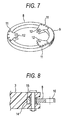
- Fig. 7 shows a structure of the moving portion 8.
- the moving portion 8 is constituted by a ring-like member made of a metal or made of an insulator, and a gear portion 9 is formed at a portion or a total of an outer periphery thereof.
- Engaging portions 11 for driving the movable contacts 5 are attached to 3 portions on an inner peripheral side of the moving portion 8.
- the engaging portion 11 is constituted by an insulating material, formed with a notched groove 12 extended in a various direction at a front end thereof, and is engaged with the projection 13 (refer to Fig.6) provided at the movable contact 5.
- Fig.8 shows a constitution for holding the moving portion 8 at the insulation maintaining portion 3.
- a recess portion 14 opened in a direction of a front end is formed at a front end of the leg portion 2 of the insulation maintaining portion 3.
- a roller 15 is rotatably attached to inside of the recess portion 14.
- An inner peripheral portion of the moving portion 8 is brought into contact with the roller, and two upper and lower faces thereof are supported by upper and lower faces of the recess portion 14.
- the moving portion 8 is held by the insulation maintaining portion 3 movably in a circumferential direction.
- a gear 16 driven to rotate by an operating portion (not illustrated) is arranged to be brought in mesh with the gear portion 9 formed at the outer periphery of the moving portion 8.
- the moving portion 8 is moved to reciprocate in the circumferential direction.
- the movable contact 5 engaged with the engaging portion 11 is moved to reciprocate between two of the fixed contacts 4 centering on the hinge portion 6.
- Notation A designates a state in which the movable contact 5 is brought into contact with one of the fixed contacts 4
- notation B designates a state in which the movable contact 5 is not brought into contact with either of the fixed contacts 4
- notation C designates a state in which the movable contact 5 is brought into contact with other of the fixed contacts 4.
- the 3 phases switch can be used as a 3 positions switch by stopping at 3 positions of A, B, C, and can be used as a 2 positions switch by stopping at only 2 positions of A, C.
- the 3 phases switch 1 can be used for various uses as 2 switches making the movable contact 5 common.
- the 3 phases switch 1 can be used as an isolator/grounding switch constituting one of them as an isolator and constituting other thereof as a grounding switch, or constituting both thereof as grounding switches.
- the 3 phases switch 1 can be used as a general switch for a serge arrester integrated with a grounding switch.
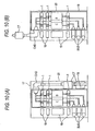
- FIG. 10 shows an inner constitution of an electricity receiving unit 17 containing the circuit shown in the single line wiring diagram of Fig.2.
- Fig.10 (A) shows an example of arranging the cable head CHD to a rear face of the unit.
- An insulating gas of SF6 gas or the like is filled in the electricity receiving unit 17 and a vessel 18 containing a main circuit apparatus is arranged in the electricity receiving unit 17.
- a bus line BUS, a breaker, an operator 19 for operating a breaker are arranged at a front face of the vessel 18 and the cable head CHD and a current transformer CT is arranged at a rear face thereof. A total of these is covered by an outer wall 20.
- Each switch of the switch DS/ES, SW/ES is constituted by the 3 phases switch 1.
- Each 3 phases switch 1 can be fixed in the vessel 18 by holding the insulation maintaining portion 3 by pertinent means.
- the circuit shown in Fig.2 is constituted by connecting respective fixed contacts, movable contacts 5 to the bus line BUS, the cable head CHD, a serge arrester, a grounding terminal and the like by a conductor.
- Fig.10 (B) shows an example of arranging the cable head CHD at the front face of the unit.
- the cable head CHD is arranged at a space formed above the operator 19 arranged at the front face of the electricity receiving unit 17.
- the current transformer CT is arranged outside of the unit.
- the respective 3 phases switches 1 are operated by the operators separate from each other and operated to open and close separately from each other.
- the 3 phases switch 1 is planarly constituted, a height thereof is restrained to be low and therefore, even when 3 pieces thereof are arranged as illustrated, a height of the electricity receiving unit 17 can be restrained to be low.
- the embodiment can be used as a single switch by using only the single fixed contact 4 and the single movable contact 5 without using the other single fixed contact 4. Further, the embodiment can be used as a single switch by only providing the single fixed contact 4 and the single movable contact 5 for the switch of the single phase by omitting the other single fixed contact in the two fixed contacts. In either of the cases, the polyphase switches can be arranged to align on one plane and therefore, downsizing can be realized similar to the above-described example.
- the polyphase switch of the invention is not limited to 3 phases but is applicable also to 2 phases, 4 phases and the like. Further, it is not necessarily needed that a number of the leg portions 2 of the insulation maintaining portion 3 is constituted by a number the same as a number of phases. For example, a 3 phases switch can also be constituted by providing 4 pieces of the leg portions 2 and arranging switches at 3 locations in 4 spaces.
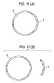
- Fig.11 shows various structures of the moving portion 8.
- Fig.11 (A) shows an example of directly forming the gear portion 9 at the moving portion 8.
- Fig.10 (B) shows an example of forming the gear portion 9 separately from the moving portion 8 to attach to the moving portion 8 by a bolt.
- the gear portion 9 may be formed only at a portion of the moving portion 8 as illustrated, the gear portion 9 can also be formed over a total range of the outer periphery of the moving portion 8.
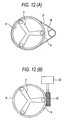
- Fig. 12 shows various constitutions for driving the moving portion 8.
- the gear portion 9 is connected to the gear 16 by a chain 21 to drive.
- the gear portion 9 is formed over the total outer periphery of the moving portion 8.
- Fig.12 (B) the gear portion 9 is connected to an operating mechanism 23 by a worm gear 22.
- the polyphase switch is planarly constituted and therefore, the height can be reduced. Further, an effect of reduced formation is significant since the switches of 3 phases can be arranged on one plane. Therefore, a height of GIS or the like can be reduced even in a case of containing a plurality of pieces of the polyphase switches in GIS or the like.
Landscapes
- Gas-Insulated Switchgears (AREA)
- Engineering & Computer Science (AREA)
- Power Engineering (AREA)
- Driving Mechanisms And Operating Circuits Of Arc-Extinguishing High-Tension Switches (AREA)
Applications Claiming Priority (2)
| Application Number | Priority Date | Filing Date | Title |
|---|---|---|---|
| JP2004111341 | 2004-04-05 | ||
| JP2004111341A JP4321333B2 (ja) | 2004-04-05 | 2004-04-05 | 多相開閉器 |
Publications (1)
| Publication Number | Publication Date |
|---|---|
| EP1585157A1 true EP1585157A1 (en) | 2005-10-12 |
Family
ID=34909475
Family Applications (1)
| Application Number | Title | Priority Date | Filing Date |
|---|---|---|---|
| EP05007447A Withdrawn EP1585157A1 (en) | 2004-04-05 | 2005-04-05 | Polyphase switch |
Country Status (3)
| Country | Link |
|---|---|
| EP (1) | EP1585157A1 (ja) |
| JP (1) | JP4321333B2 (ja) |
| KR (1) | KR100691552B1 (ja) |
Cited By (4)
| Publication number | Priority date | Publication date | Assignee | Title |
|---|---|---|---|---|
| EP2346059A3 (de) * | 2010-01-18 | 2012-08-29 | ABB Technology AG | Vorrichtung zum schalten eines Stromkreises |
| WO2017173819A1 (zh) * | 2016-04-08 | 2017-10-12 | 首瑞(天津)电气设备有限公司 | 用于旋转隔离开关的触头模块和旋转隔离开关 |
| US11063410B2 (en) * | 2017-06-23 | 2021-07-13 | Mitsubishi Electric Corporation | Switchgear |
| EP4456106A1 (en) * | 2023-04-23 | 2024-10-30 | ABB Schweiz AG | Switchgear |
Families Citing this family (2)
| Publication number | Priority date | Publication date | Assignee | Title |
|---|---|---|---|---|
| EP2312710B1 (en) * | 2009-10-13 | 2016-05-04 | ABB Technology AG | Three-phase gasinsulated medium voltage switching device |
| KR101379158B1 (ko) * | 2012-03-26 | 2014-04-02 | 현대중공업 주식회사 | 단로기 및 접지개폐기를 구비한 가스절연개폐장치의 계기용 변성기 |
Citations (4)
| Publication number | Priority date | Publication date | Assignee | Title |
|---|---|---|---|---|
| US3530263A (en) * | 1967-09-28 | 1970-09-22 | English Electric Co Ltd | Switching isolators |
| US5560474A (en) * | 1994-08-15 | 1996-10-01 | Southern Electrical Equipment Company | Electro/mechanical actuator for circuit disconnect/connect apparatus for overhead power lines |
| US5821486A (en) * | 1996-08-26 | 1998-10-13 | S&C Electric Company | Switch for hookstick operation |
| WO1999066522A1 (en) * | 1998-06-19 | 1999-12-23 | Abb Sp. Z.O.O. | Integrated unit for an air-insulated high voltage switching station |
-
2004
- 2004-04-05 JP JP2004111341A patent/JP4321333B2/ja not_active Expired - Lifetime
-
2005
- 2005-04-04 KR KR20050028007A patent/KR100691552B1/ko not_active Expired - Fee Related
- 2005-04-05 EP EP05007447A patent/EP1585157A1/en not_active Withdrawn
Patent Citations (4)
| Publication number | Priority date | Publication date | Assignee | Title |
|---|---|---|---|---|
| US3530263A (en) * | 1967-09-28 | 1970-09-22 | English Electric Co Ltd | Switching isolators |
| US5560474A (en) * | 1994-08-15 | 1996-10-01 | Southern Electrical Equipment Company | Electro/mechanical actuator for circuit disconnect/connect apparatus for overhead power lines |
| US5821486A (en) * | 1996-08-26 | 1998-10-13 | S&C Electric Company | Switch for hookstick operation |
| WO1999066522A1 (en) * | 1998-06-19 | 1999-12-23 | Abb Sp. Z.O.O. | Integrated unit for an air-insulated high voltage switching station |
Cited By (4)
| Publication number | Priority date | Publication date | Assignee | Title |
|---|---|---|---|---|
| EP2346059A3 (de) * | 2010-01-18 | 2012-08-29 | ABB Technology AG | Vorrichtung zum schalten eines Stromkreises |
| WO2017173819A1 (zh) * | 2016-04-08 | 2017-10-12 | 首瑞(天津)电气设备有限公司 | 用于旋转隔离开关的触头模块和旋转隔离开关 |
| US11063410B2 (en) * | 2017-06-23 | 2021-07-13 | Mitsubishi Electric Corporation | Switchgear |
| EP4456106A1 (en) * | 2023-04-23 | 2024-10-30 | ABB Schweiz AG | Switchgear |
Also Published As
| Publication number | Publication date |
|---|---|
| KR100691552B1 (ko) | 2007-03-09 |
| KR20060045480A (ko) | 2006-05-17 |
| JP4321333B2 (ja) | 2009-08-26 |
| JP2005294214A (ja) | 2005-10-20 |
Similar Documents
| Publication | Publication Date | Title |
|---|---|---|
| EP2546850B1 (en) | Switchgear and method for operating switchgear | |
| US5003427A (en) | Metal encapsulated multi-phase high voltage switching system filled with compressed gas | |
| JP4329923B2 (ja) | ガス絶縁スイッチギヤ | |
| US7829814B2 (en) | Vacuum circuit interrupter grounding assembly | |
| US6559403B2 (en) | Three-position electrical switch having a switching element that is movable in axial translation | |
| CA2488759A1 (en) | Isolator/circuit-breaker device for electric substations | |
| US8350169B2 (en) | Three-positions disconnector for medium voltage panels | |
| DE69731058T2 (de) | Vakuumschalter mit Trennschalter | |
| JPWO2002067394A1 (ja) | ガス絶縁開閉装置 | |
| EP1585157A1 (en) | Polyphase switch | |
| JP2000067708A (ja) | 断路器、接地開閉器及び接地開閉器付断路器 | |
| JP5183794B2 (ja) | スイッチギヤ | |
| JP4040954B2 (ja) | 真空開閉装置 | |
| KR101157188B1 (ko) | 고체절연 개폐장치 | |
| CN209785824U (zh) | 一种具有接地联锁功能的组合电器 | |
| JPH11355926A (ja) | ガス絶縁開閉器 | |
| JPH11155209A (ja) | ガス絶縁キュービクル | |
| KR101469308B1 (ko) | 가스 절연 개폐장치 | |
| CN102017038B (zh) | 中压开关装置 | |
| CN209786609U (zh) | 一种具有合闸闭锁功能的组合电器 | |
| JP2000357441A (ja) | スイッチギヤ | |
| KR20020083270A (ko) | 가스 절연 배전반 | |
| JP2004320883A (ja) | ガス絶縁開閉装置用断路装置 | |
| JP2000078714A (ja) | ガス絶縁開閉装置の簡易断路器 | |
| JPH0739048A (ja) | ガス絶縁開閉装置 |
Legal Events
| Date | Code | Title | Description |
|---|---|---|---|
| PUAI | Public reference made under article 153(3) epc to a published international application that has entered the european phase |
Free format text: ORIGINAL CODE: 0009012 |
|
| AK | Designated contracting states |
Kind code of ref document: A1 Designated state(s): AT BE BG CH CY CZ DE DK EE ES FI FR GB GR HU IE IS IT LI LT LU MC NL PL PT RO SE SI SK TR |
|
| AX | Request for extension of the european patent |
Extension state: AL BA HR LV MK YU |
|
| 17P | Request for examination filed |
Effective date: 20051215 |
|
| AKX | Designation fees paid |
Designated state(s): DE FR |
|
| STAA | Information on the status of an ep patent application or granted ep patent |
Free format text: STATUS: THE APPLICATION IS DEEMED TO BE WITHDRAWN |
|
| 18D | Application deemed to be withdrawn |
Effective date: 20071101 |