EP1584832B1 - Verfahren zum Ansteuern des Kupplungsmomentes einer Kupplung eines automatisierten Getriebes und eine Vorrichtung zum Durchführen des Verfahrens - Google Patents
Verfahren zum Ansteuern des Kupplungsmomentes einer Kupplung eines automatisierten Getriebes und eine Vorrichtung zum Durchführen des Verfahrens Download PDFInfo
- Publication number
- EP1584832B1 EP1584832B1 EP05004604A EP05004604A EP1584832B1 EP 1584832 B1 EP1584832 B1 EP 1584832B1 EP 05004604 A EP05004604 A EP 05004604A EP 05004604 A EP05004604 A EP 05004604A EP 1584832 B1 EP1584832 B1 EP 1584832B1
- Authority
- EP
- European Patent Office
- Prior art keywords
- rotational speed
- clutch torque
- function
- speed
- clutch
- Prior art date
- Legal status (The legal status is an assumption and is not a legal conclusion. Google has not performed a legal analysis and makes no representation as to the accuracy of the status listed.)
- Not-in-force
Links
Images
Classifications
-
- F—MECHANICAL ENGINEERING; LIGHTING; HEATING; WEAPONS; BLASTING
- F16—ENGINEERING ELEMENTS AND UNITS; GENERAL MEASURES FOR PRODUCING AND MAINTAINING EFFECTIVE FUNCTIONING OF MACHINES OR INSTALLATIONS; THERMAL INSULATION IN GENERAL
- F16D—COUPLINGS FOR TRANSMITTING ROTATION; CLUTCHES; BRAKES
- F16D48/00—External control of clutches
- F16D48/06—Control by electric or electronic means, e.g. of fluid pressure
-
- B—PERFORMING OPERATIONS; TRANSPORTING
- B60—VEHICLES IN GENERAL
- B60W—CONJOINT CONTROL OF VEHICLE SUB-UNITS OF DIFFERENT TYPE OR DIFFERENT FUNCTION; CONTROL SYSTEMS SPECIALLY ADAPTED FOR HYBRID VEHICLES; ROAD VEHICLE DRIVE CONTROL SYSTEMS FOR PURPOSES NOT RELATED TO THE CONTROL OF A PARTICULAR SUB-UNIT
- B60W30/00—Purposes of road vehicle drive control systems not related to the control of a particular sub-unit, e.g. of systems using conjoint control of vehicle sub-units, or advanced driver assistance systems for ensuring comfort, stability and safety or drive control systems for propelling or retarding the vehicle
- B60W30/18—Propelling the vehicle
- B60W30/18009—Propelling the vehicle related to particular drive situations
- B60W30/18063—Creeping
-
- B—PERFORMING OPERATIONS; TRANSPORTING
- B60—VEHICLES IN GENERAL
- B60W—CONJOINT CONTROL OF VEHICLE SUB-UNITS OF DIFFERENT TYPE OR DIFFERENT FUNCTION; CONTROL SYSTEMS SPECIALLY ADAPTED FOR HYBRID VEHICLES; ROAD VEHICLE DRIVE CONTROL SYSTEMS FOR PURPOSES NOT RELATED TO THE CONTROL OF A PARTICULAR SUB-UNIT
- B60W2510/00—Input parameters relating to a particular sub-units
- B60W2510/02—Clutches
- B60W2510/0241—Clutch slip, i.e. difference between input and output speeds
- B60W2510/025—Slip change rate
-
- B—PERFORMING OPERATIONS; TRANSPORTING
- B60—VEHICLES IN GENERAL
- B60W—CONJOINT CONTROL OF VEHICLE SUB-UNITS OF DIFFERENT TYPE OR DIFFERENT FUNCTION; CONTROL SYSTEMS SPECIALLY ADAPTED FOR HYBRID VEHICLES; ROAD VEHICLE DRIVE CONTROL SYSTEMS FOR PURPOSES NOT RELATED TO THE CONTROL OF A PARTICULAR SUB-UNIT
- B60W2520/00—Input parameters relating to overall vehicle dynamics
- B60W2520/10—Longitudinal speed
-
- B—PERFORMING OPERATIONS; TRANSPORTING
- B60—VEHICLES IN GENERAL
- B60W—CONJOINT CONTROL OF VEHICLE SUB-UNITS OF DIFFERENT TYPE OR DIFFERENT FUNCTION; CONTROL SYSTEMS SPECIALLY ADAPTED FOR HYBRID VEHICLES; ROAD VEHICLE DRIVE CONTROL SYSTEMS FOR PURPOSES NOT RELATED TO THE CONTROL OF A PARTICULAR SUB-UNIT
- B60W2710/00—Output or target parameters relating to a particular sub-units
- B60W2710/02—Clutches
- B60W2710/027—Clutch torque
-
- F—MECHANICAL ENGINEERING; LIGHTING; HEATING; WEAPONS; BLASTING
- F16—ENGINEERING ELEMENTS AND UNITS; GENERAL MEASURES FOR PRODUCING AND MAINTAINING EFFECTIVE FUNCTIONING OF MACHINES OR INSTALLATIONS; THERMAL INSULATION IN GENERAL
- F16D—COUPLINGS FOR TRANSMITTING ROTATION; CLUTCHES; BRAKES
- F16D2500/00—External control of clutches by electric or electronic means
- F16D2500/30—Signal inputs
- F16D2500/31—Signal inputs from the vehicle
- F16D2500/3108—Vehicle speed
-
- F—MECHANICAL ENGINEERING; LIGHTING; HEATING; WEAPONS; BLASTING
- F16—ENGINEERING ELEMENTS AND UNITS; GENERAL MEASURES FOR PRODUCING AND MAINTAINING EFFECTIVE FUNCTIONING OF MACHINES OR INSTALLATIONS; THERMAL INSULATION IN GENERAL
- F16D—COUPLINGS FOR TRANSMITTING ROTATION; CLUTCHES; BRAKES
- F16D2500/00—External control of clutches by electric or electronic means
- F16D2500/50—Problem to be solved by the control system
- F16D2500/502—Relating the clutch
- F16D2500/50206—Creep control
-
- F—MECHANICAL ENGINEERING; LIGHTING; HEATING; WEAPONS; BLASTING
- F16—ENGINEERING ELEMENTS AND UNITS; GENERAL MEASURES FOR PRODUCING AND MAINTAINING EFFECTIVE FUNCTIONING OF MACHINES OR INSTALLATIONS; THERMAL INSULATION IN GENERAL
- F16D—COUPLINGS FOR TRANSMITTING ROTATION; CLUTCHES; BRAKES
- F16D2500/00—External control of clutches by electric or electronic means
- F16D2500/50—Problem to be solved by the control system
- F16D2500/506—Relating the transmission
- F16D2500/50692—Simulate the characteristics of a torque converter
-
- F—MECHANICAL ENGINEERING; LIGHTING; HEATING; WEAPONS; BLASTING
- F16—ENGINEERING ELEMENTS AND UNITS; GENERAL MEASURES FOR PRODUCING AND MAINTAINING EFFECTIVE FUNCTIONING OF MACHINES OR INSTALLATIONS; THERMAL INSULATION IN GENERAL
- F16D—COUPLINGS FOR TRANSMITTING ROTATION; CLUTCHES; BRAKES
- F16D2500/00—External control of clutches by electric or electronic means
- F16D2500/70—Details about the implementation of the control system
- F16D2500/704—Output parameters from the control unit; Target parameters to be controlled
- F16D2500/70402—Actuator parameters
- F16D2500/7041—Position
- F16D2500/70412—Clutch position change rate
-
- F—MECHANICAL ENGINEERING; LIGHTING; HEATING; WEAPONS; BLASTING
- F16—ENGINEERING ELEMENTS AND UNITS; GENERAL MEASURES FOR PRODUCING AND MAINTAINING EFFECTIVE FUNCTIONING OF MACHINES OR INSTALLATIONS; THERMAL INSULATION IN GENERAL
- F16D—COUPLINGS FOR TRANSMITTING ROTATION; CLUTCHES; BRAKES
- F16D2500/00—External control of clutches by electric or electronic means
- F16D2500/70—Details about the implementation of the control system
- F16D2500/704—Output parameters from the control unit; Target parameters to be controlled
- F16D2500/70422—Clutch parameters
- F16D2500/70438—From the output shaft
- F16D2500/7044—Output shaft torque
Definitions
- the present invention relates to a method for controlling the clutch torque of a clutch of an automated transmission in a drive train of a vehicle with activated creep function. Furthermore, the invention relates to a device, in particular for carrying out the method for driving the clutch torque.
- the clutch torque is changed as a function of a variable, the Kriechphase of the vehicle descriptive operating parameter of the vehicle. This means that one or more operating parameters of the vehicle are monitored, which describe a slow drive or crawl of the vehicle, and that depending on the operating parameter or the operating parameters, the torque transmitted by the clutch is changed.
- the clutch torque may be initially reduced at a higher speed, depending on the operating parameter selected, and thereafter the clutch torque reduced at a lower speed, such that compared to a linear reduction in the clutch torque speed more comfortable crawl space is available.
- the EP 1 403 547 A2 further discloses a clutch control for a speed-controlled creep, in which a minimum clutch torque is specified from a predetermined maximum speed.
- the present invention has for its object to propose a method of the type mentioned, which further improves the creep behavior in vehicles with automated transmissions.
- This object can be achieved by an inventive method for driving the clutch torque of a clutch of an automated transmission in a drive train of a vehicle with activated creep, wherein the clutch torque is controlled in dependence of the slip on the clutch and / or in dependence of the speed of the vehicle.
- a further aspect of the invention provides that a desired clutch torque is determined at least as a function of a predetermined slip speed of the clutch.
- the clutch target torque can be determined.
- the nominal slip speed can be determined, for example, from the difference between the engine idle speed and a driven-side speed.
- the difference may also be defined from the nominal read speed of the engine and the current (calculated) transmission input speed.
- the creep torque is not primarily directly dependent on the actual actual engine speed, so that any oscillations of engine speed and clutch desired torque that may arise in the calculation using the real slip on the clutch can be avoided. Only at very low real engine speeds, for example, these can be taken directly into account, the
- Clutch torque in such cases is not further increased or decreased to avoid stalling of the engine.
- the desired clutch torque is determined from a function or the like proportional to the rated slip speed, the desired clutch torque being suitably limited by calibratable quantities.
- the respective desired clutch torque is limited at the top by a maximum desired clutch torque M max up to a minimum vehicle speed V mim .
- a minimum desired clutch torque M min is limited from a maximum vehicle speed V max .
- the entry into the creep phase can take place both when the vehicle is at a standstill and when a vehicle is rolling.
- calibrated, time and / or nennschlupfabzanden ramp functions can be used with different slopes to build the clutch desired torque in the inventive method, the current clutch desired torque Start value is determined as a function of the nominal slip.
- the clutch desired torque can be calculated according to the second ramp function according to the inventive method, wherein after completion of the ramp functions, the clutch desired torque during the creep phase can always be set to the maximum value calculated at the beginning.
- an inventive development of the present invention may provide that the inventive method also realizes a suitable stall protection in the control of the clutch torque.
- it can be checked as part of the stalling protection whether the respective current engine speed is above an applicable limit speed for the stalling protection. If the current engine speed is above this limit speed, z. B. be provided that the calculated clutch desired torque is maintained. In contrast, when falling below the limit speed z. B. an immediate opening of the clutch or the like may be provided. Otherwise, it can be decided for example by a corresponding time criterion on the maintenance of the clutch torque from the previous pass of the creep or via a gradual reduction of the clutch torque.
- the object underlying the invention can also be achieved by a device for driving the clutch torque of a clutch of an automated transmission in a drive train of a vehicle with activated creep function, wherein at least one control device is provided, which the clutch torque in dependence of the slip on the clutch and / or depending on the speed of the vehicle.
- the proposed device can also be used to carry out the method according to the invention.
- An application especially in vehicles with automated manual transmission (ASG) or a parallel shift transmission (PSG) is particularly useful.
- the creep behavior or the creep behavior of a vehicle with a parallel shift transmission can be improved by the method according to the invention by approximating the slip-dependent creep behavior of automatic vehicles with a hydraulic converter.
- the desired clutch torque is not determined based on the real slip, but rather on the basis of a nominal slip speed as the difference of a nominal and nominal idle speed and a calculated transmission input shaft speed.
- the actual engine speed may preferably be taken into account for preventing stalling of the engine.
- the clutch desired torque can be built up via calibratable, time-dependent and clutch torque-dependent ramp functions.
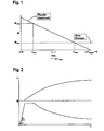
- FIG. 1 shows a possible strategy according to the inventive method for calculating the desired clutch torque from a function proportional to the nominal slip speed function, wherein for comparison a clutch desired torque curve is additionally shown in a transmission with a hydrodynamic converter.
- the desired clutch torque curve according to the invention is limited by calibratable variables upwards or downwards. Upwards, the limit is given by the maximum desired clutch torque value M max, which is present up to a minimum vehicle speed V min . Thereafter, the desired clutch torque curve is represented by a ramp function, which is up to a maximum vehicle speed V max , at which then the delimitation of the minimum clutch desired torque value M min occurs.
- the entry into the creep phase can take place both when the vehicle is at a standstill and when the vehicle is rolling.
- calibratable, time-dependent and slip-dependent ramp functions of different pitch are used to build up the desired clutch torque.
- the current clutch desired torque serves as a starting value
- the maximum value is determined depending nennschlupftouch.
- FIG. 2 Shown in the course of the clutch torque and the vehicle speed when Ankriechen from standstill over time is shown. Starting from the clutch torque at standstill of the vehicle (0 Nm), the torque build-up takes place via two successive ramp functions with the pitch angles ⁇ and ⁇ , respectively, until the maximum value of the nominal clutch torque has been reached. From this time comes the in FIG. 1 shown ramp function used.
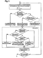
- FIG. 3 is a flowchart of the clutch torque calculation according to the inventive method when creeping illustrated, which indicates the process, as it is cycled during a creep phase.
- a downstream stall protection is exemplified. If the current engine speed is above an applied stall protection threshold (G), the clutch torque calculated in steps (A) through (F) can be maintained. Otherwise, it is checked by the method whether the current engine speed is running against the specified stall speed, with an undershooting of the speed limit results in the immediate opening of the clutch (I). Otherwise, a time criterion (J) can be achieved by maintaining the clutch torque from the previous run (K) or by gradually reducing the desired clutch torque (L).
- G applied stall protection threshold
- J time criterion
Description
- Die vorliegende Erfindung betrifft ein Verfahren zum Ansteuern des Kupplungsmomentes einer Kupplung eines automatisierten Getriebes in einem Antriebsstrang eines Fahrzeuges bei aktivierter Kriechfunktion. Ferner betrifft die Erfindung eine Vorrichtung, insbesondere zum Durchführen des Verfahrens zum Ansteuern des Kupplungsmomentes.
- Aus der Druckschrift
DE 197 33 465 A1 ist eine Anordnung zur Steuerung einer automatisierten Kupplung und ein Verfahren zum Steuern einer automatisierten Kupplung eines Kraftfahrzeuges, insbesondere bei geringen Fahrzeuggeschwindigkeiten, bekannt. Die bekannte Anordnung weist Mittel zum Erfassen der Betätigung des Bremspedals, des Rückwärtsrollens und des Vorwärtsrollens auf, deren Ausgangssignale einer Entscheidungsvorrichtung zugeordnet werden, welche entsprechend der Ausgangssignale entscheidet, welcher Fahrzustand vorliegt, und entsprechend des Fahrzustandes die Steuerung der automatisierten Kupplung an verschiedene, mit der Entscheidungsvorrichtung verbundene Steuereinrichtungen übergibt. Die verschiedenen Steuervorrichtungen steuern die automatisierte Kupplung derart an, dass sich das Fahrzeug bei niedrigen Fahrzeuggeschwindigkeiten wie ein Fahrzeug mit einem hydrodynamischen Drehmomentenwandler verhält. - Des weiteren ist aus der Druckschrift
DE 102 28 029 A1 ein Verfahren zur Veränderung des Kupplungsmomentes einer Kupplung im Antriebsstrang eines Fahrzeuges mit einem automatisierten Schaltgetriebe bekannt. Bei dem bekannten Verfahren wird das Kupplungsmoment in Abhängigkeit eines variablen, die Kriechphase des Fahrzeuges beschreibenden Betriebsparameters des Fahrzeuges verändert. Dies bedeutet, dass ein oder mehrere Betriebsparameter des Fahrzeuges überwacht werden, die eine Langsamfahrt oder Kriechfahrt des Fahrzeuges beschreiben, und dass in Abhängigkeit des Betriebsparameters oder der Betriebsparameter das von der Kupplung übertragene Moment verändert wird. - Dadurch wird erreicht, dass die Kriechfahrt des Fahrzeuges ohne die Gefahr eines Abwürgens des Motors verbessert werden kann, da nicht mehr nur eine digitale Information in der Form des Bremslichtschalters ausgewertet wird, sondern einer oder mehrere die Kriechfahrt des Fahrzeugs beschreibende, sich nicht digital verändernde Betriebsparameter ausgewertet werden. Beispielsweise kann bei Gefahr des Abwürgens des Motors das Kupplungsmoment zunächst mit höherer Geschwindigkeit verringert werden, und zwar in Abhängigkeit des gewählten Betriebsparameters, und danach das Kupplungsmoment mit einer niedrigeren Geschwindigkeit verringert werden, so dass, verglichen mit einer linearen Verringerung der Geschwindigkeit des Kupplungsmoments, eine komfortablere Kriechfahrt zur Verfügung steht.
- Die
EP 1 403 547 A2 offenbart weiterhin eine Kupplungssteuerung für ein geschwindigkeitsgeregeltes Kriechen, bei dem ab einer vorzugebenden Maximalgeschwindigkeit ein minimales Kupplungsmoment vorgegeben wird. - Der vorliegenden Erfindung liegt die Aufgabe zugrunde, ein Verfahren der eingangs genannten Gattung vorzuschlagen, welche das Kriechverhalten bei Fahrzeugen mit automatisierten Getrieben weiter verbessert.
- Diese Aufgabe kann durch ein erfindungsgemäßes Verfahren zum Ansteuern des Kupplungsmomentes einer Kupplung eines automatisierten Getriebes in einem Antriebsstrang eines Fahrzeuges bei aktivierter Kriechfunktion gelöst werden, wobei das Kupplungsmoment in Abhängigkeit des Schlupfes an der Kupplung und/oder in Abhängigkeit der Geschwindigkeit des Fahrzeuges angesteuert wird.
- Auf diese Weise wird eine schlupf bzw. geschwindigkeitsabhängige Kriechstrategie für ein Fahrzeug mit einem automatisierten mechanischen Getriebe und Reibkupplungen realisiert. Insbesondere kann bei großem Schlupf an der Kupplung auch ein großes Moment übertragen werden, welches bedeutet, dass beim Ankriechen aus dem Stillstand zunächst das maximale Kriechmoment übertragen wird, welches dann mit sinkender Schlupfdrehzahl bzw. wachsender Fahrzeuggeschwindigkeit stetig abnehmen kann. Bei einem Gleichlauf von An- und Abtrieb kann vorgesehen sein, dass kein Moment mehr übertragen wird.
- Ein weiterer Aspekt der Erfindung sieht vor, dass ein Kupplungssollmoment zumindest in Abhängigkeit einer vorgegebenen Schlupfdrehzahl der Kupplung bestimmt wird. Somit kann bei einer Kriechphase des Fahrzeuges anhand einer Nennschlupfdrehzahl das Kupplungssollmoment bestimmt werden. Die Nennschlupfdrehzahl kann beispielsweise aus der Differenz der Motorleerlaufdrehzahl und einer abtriebsseitigen Drehzahl ermittelt werden. Beispielsweise kann die Differenz auch aus der Nennlesrlaufdrehzahl des Motors und der aktuellen (berechneten) Getriebeeingangswellendrehzahl definiert werden. Alternativ kann als abtriebsseitige Drehzahl auch eine z.B. gemessene Raddrehzahl verwendet werden.
- Somit ist das Kriechmoment nicht in erster Linie direkt von der tatsächlichen aktuellen Motordrehzahl abhängig, so dass etwaige Schwingungen von Motordrehzahl und Kupplungssollmoment vermieden werden können, welche bei der Berechnung unter Verwendung des realen Schlupfes an der Kupplung entstehen können. Erst bei sehr niedrigen realen Motordrehzahlen können diese beispielsweise direkt berücksichtigt werden, wobei das
- Kupplungssollmoment in derartigen Fällen nicht weiter erhöht bzw. verringert wird, um ein Abwürgen des Motors zu vermeiden.
- Es ist vorgesehen, dass das Kupplungssollmoment aus einer der Nennschlupfdrehzahl proportionalen Funktion oder dergleichen bestimmt wird, wobei das Kupplungssollmoment in geeigneter Weise durch kalibrierbare Größen begrenzt wird. Das jeweilige Kupplungssollmoment ist nach oben hin durch ein maximales Kupplungssollmoment Mmax bis zu einer minimalen Fahrzeuggeschwindigkeit Vmim begrenzt. Nach unten hin ist ein minimales Kupplungssollmoment Mmin ab einer maximalen Fahrzeuggeschwindigkeit Vmax begrenzt.
- Der Eintritt in die Kriechphase kann sowohl bei einem Stillstand des Fahrzeuges als auch bei einem rollenden Fahrzeug erfolgen. Um trotz des für die gewünschte Verhaltensweise notwendigen großen Anfangskupplungsmoments stets weiche Übergänge ohne spürbare Schläge beim Kriechen zu erreichen, können bei dem erfindungsgemäßen Verfahren kalibrierbare, zeit- und/oder nennschlupfabhängige Rampenfunktionen mit unterschiedlichen Steigungen zum Aufbau des Kupplungssollmomentes verwendet werden, wobei das aktuelle Kupplungssollmoment als Startwert einen Maximalwert in Abhängigkeit des Nennschlupfes bestimmt wird.
- Wenn ein zyklischer Durchlauf während einer Kriechphase absolviert wird, kann nach der Berechnung eines maximalen Kupplungsmomentes geprüft werden, ob eine applizierbare Startrampenfunktion nicht mehr verwendet werden muss, welches von der Höhe des Kupplungsmomentes beim Eintritt in die Kriechphase und von der seither vergangenen Zeit abhängig ist.
- Wenn die applizierbare Startrampenfunktion nicht verwendet wird, kann geprüft werden, ob eine zweite Rampenfunktion, welche in jedem Fall durchlaufen werden sollte, bereits beendet ist. Falls dies nicht der Fall ist, kann das Kupplungssollmoment nach der zweiten Rampenfunktion gemäß dem erfindungsgemäßen Verfahren errechnet werden, wobei nach Beendigung der Rampenfunktionen das Kupplungssollmoment während der Kriechphase stets auf den am Anfang berechneten Maximalwert gesetzt werden kann.
- Eine erfindungsgemäße Weiterbildung der vorliegenden Erfindung kann vorsehen, dass das erfindungsgemäße Verfahren auch einen geeigneten Abwürgeschutz bei der Ansteuerung des Kupplungsmomentes realisiert. Vorzugsweise kann im Rahmen des Abwürgeschutzes geprüft werden, ob die jeweils aktuelle Motordrehzahl über einer applizierbaren Grenzdrehzahl für den Abwürgeschutz liegt. Wenn die aktuelle Motordrehzahl über dieser Grenzwertdrehzahl liegt, kann z. B. vorgesehen sein, dass das berechnete Kupplungssollmoment beibehalten wird. Dagegen kann bei Unterschreitung der Grenzdrehzahl z. B. ein sofortiges Öffnen der Kupplung oder dergleichen vorgesehen sein. Ansonsten kann beispielsweise durch ein entsprechendes Zeitkriterium über die Beibehaltung des Kupplungsmomentes aus dem vorherigen Durchlauf der Kriechphase bzw. über eine schrittweise Verringerung des Kupplungsmomentes entschieden werden.
- Des weiteren kann die der Erfindung zugrunde liegende Aufgabe auch durch eine Vorrichtung zum Ansteuern des Kupplungsmomentes einer Kupplung eines automatisierten Getriebes in einem Antriebsstrang eines Fahrzeuges bei aktivierter Kriechfunktion gelöst werden, wobei zumindest eine Steuereinrichtung vorgesehen ist, welche das Kupplungsmoment in Abhängigkeit des Schlupfes an der Kupplung und/oder in Abhängigkeit der Geschwindigkeit des Fahrzeuges ansteuert.
- Insbesondere kann die vorgeschlagene Vorrichtung auch zum Durchführen des erfindungsgemäßen Verfahrens verwendet werden. Eine Anwendung insbesondere bei Fahrzeugen mit automatisiertem Schaltgetriebe (ASG) oder einem Parallelschaltgetriebe (PSG) ist besonders sinnvoll.
- Zusammenfassend kann das Kriechverhalten bzw. das Ankriechverhalten eines Fahrzeuges mit einem Parallelschaltgetriebe durch das erfindungsgemäße Verfahren verbessert werden, indem das schlupfabhängige Kriechverhalten von Automatikfahrzeugen mit hydraulischem Wandler angenähert wird. Bei der erfindungsgemäßen Lösung wird das Kupplungssollmoment nicht anhand des realen Schlupfes, sondern vielmehr anhand einer Nennschlupfdrehzahl als Differenz einer Soll- bzw. Nennleerlaufdrehzahl und einer berechneten Getriebeeingangswellendrehzahl bestimmt. Hierdurch können Schwingungen von der Motordrehzahl und des Kupplungsmomentes vermieden werden. Die aktuelle Motordrehzahl kann vorzugsweise für die Verhinderung des Abwürgens des Motors berücksichtigt werden. Um sowohl bei einem stehenden als auch bei einem rollenden Fahrzeug sanfte, schlagfreie Übergänge zum Kriechen zu erhalten, kann das Kupplungssollmoment über kalibrierbare, zeit- und kupplungsmomentabhängige Rampenfunktionen aufgebaut werden.
- Nachfolgend wird die vorliegende Erfindung anhand der Zeichnungen weiter erläutert. Es zeigen:
- Figur 1
- Kupplungssollmomentenverläufe über der Fahrzeuggeschwindigkeit;
- Figur 2
- einen Verlauf des Kupplungssollmomentes und der Fahrzeuggeschwindigkeit beim Ankriechen aus dem Stillstand über der Zeit; und
- Figur 3
- ein Ablaufdiagramm einer erfindungsgemäßen Kupplungssollmomentenberechnung beim Kriechen mit einem Abwürgeschutz.
- In
Figur 1 ist eine mögliche Strategie gemäß dem erfindungsgemäßen Verfahren zum Berechnen des Kupplungssollmomentes aus einem der Nennschlupfdrehzahl proportionalen Funktion dargestellt, wobei zum Vergleich ein Kupplungssollmomentenverlauf bei einem Getriebe mit einem hydrodynamischen Wandler zusätzlich dargestellt ist. - Der erfindungsgemäße Kupplungssollmomentenverlauf wird durch kalibrierbare Größen nach oben bzw. nach unten hin begrenzt. Nach oben erfolgt die Begrenzung durch den maximalen Kupplungssollmomentenwert Mmax, welcher bis zu einer minimalen Fahrzeuggeschwindigkeit Vmin vorliegt. Danach wird der Kupplungssollmomentenverlauf durch eine Rampenfunktion dargestellt, welche bis zu einer maximalen Fahrzeuggeschwindigkeit Vmax vorliegt, bei der dann die Abgrenzung des minimalen Kupplungssollmomentenwertes Mmin erfolgt.
- Der Eintritt in die Kriechphase kann sowohl bei einem Stillstand des Fahrzeuges als auch bei rollendem Fahrzeug erfolgen. Um die trotz des für die gewünschte Verhaltensweise notwendigen großen Anfangsmoments stets weichen Übergänge ohne spürbare Schläge beim Kriechen zu erreichen, werden kalibrierbare, zeit- und nennschlupfabhängige Rampenfunktionen unterschiedlicher Steigung zum Aufbau des Kupplungssollmomentes verwendet. Hierbei dient das aktuelle Kupplungssollmoment als Startwert, wobei der Maximalwert nennschlupfabhängig bestimmt wird.
- Exemplarisch ist dieses Vorgehen in
Figur 2 gezeigt, in der der Verlauf des Kupplungsmomentes und der Fahrzeuggeschwindigkeit beim Ankriechen aus dem Stillstand über der Zeit dargestellt ist. Ausgehend von dem Kupplungsmoment bei Stillstand des Fahrzeuges (0 Nm), erfolgt der Momentenaufbau über zwei aufeinander folgende Rampenfunktionen mit den Steigungswinkeln α bzw. β, bis der Maximalwert des Kupplungssollmomentes erreicht worden ist. Ab diesem Zeitpunkt kommt die inFigur 1 dargestellte Rampenfunktion zum Einsatz. - In
Figur 3 ist ein Ablaufdiagramm der Kupplungssollmomentenberechnung gemäß dem erfindungsgemäßen Verfahren beim Kriechen beispielhaft dargestellt, welche den Ablauf andeutet, wie er während einer Kriechphase zyklisch durchlaufen wird. - Nach der nennschlupf- bzw. geschwindigkeitsabhängigen Berechnung des aktuell maximalen Kupplungsmoments (A) wird geprüft, ob die applizierbare Startrampenfunktion nicht mehr durchlaufen werden muss (B). Dies hängt zum Einen von der Höhe des Kupplungsmoments beim Eintritt in die Kriechphase und zum Anderen von der seither vergangenen Zeit ab. Wenn dies nicht der Fall ist, wird das Kupplungssollmoment in Abhängigkeit der Applizierung der ersten Rampenfunktion berechnet (C), andernfalls erfolgt die Prüfung, ob die zweite Rampenfunktion, die in jedem Fall durchlaufen werden muss, bereits beendet wurde (D). Falls nicht, wird das Kupplungssollmoment nach der Vorschrift der zweiten Rampenfunktion (E) berechnet. Nach dem Beenden der Rampenfunktionen wird das Kupplungssollmoment während der Kriechphase stets auf den unter (A) berechneten Maximalwert gesetzt (F).
- Im unteren Teil des in
Figur 3 gezeigten Ablaufdiagramms ist ein nachgelagerter Abwürgeschutz beispielhaft dargestellt. Wenn die aktuelle Motordrehzahl über einer applizierten Grenze für die Aktivierung des Abwürgeschutzes liegt (G), kann das in den Verfahrensschritten (A) bis (F) berechnete Kupplungsmoment beibehalten werden. Ansonsten wird durch das Verfahren geprüft, ob die derzeitige Motordrehzahl gegen die spezifizierte Abwürgedrehzahl verläuft, wobei eine Unterschreitung der Drehzahlgrenze das sofortige Öffnen der Kupplung zur Folge hat (I). Ansonsten kann ein Zeitkriterium (J) über die Beibehaltung des Kupplungsmomentes aus dem vorherigen Durchlauf (K) oder eine schrittweise Verringerung des Kupplungssollmomentes (L) erfolgen.
Claims (12)
- Verfahren zum Ansteuern des Kupplungsmomentes einer Kupplung eines automatisierten Getriebes in einem Antriebsstrang eines Fahrzeuges bei aktivierter Kriechfunktion, wobei das Kupplungsmoment in Abhängigkeit des Schlupfes und/oder in Abhängigkeit der Geschwindigkeit des Fahrzeuges angesteuert wird, ein Kupplungssollmoment zumindest in Abhängigkeit einer vorgegebenen Schlupfdrehzahl der Kupplung ermittelt wird, als Schlupfdrehzahl die Nennschlupfdrehzahl verwendet wird, welche aus der Differenz der Motorieerlaufdrehzahl und einer abtriebsseitigen Drehzahl ermittelt wird, das Kupplungssollmoment anhand einer der Nennschlupfdrehzahl proportionalen Funktion bestimmt wird, wobei das Kupplungssollmoment durch kalibrierbare Größen begrenzt wird und das minimale Kupplungssollmoment (Mmin) ab einer maximalen Geschwindigkeit (vmax) eingestellt wird, dadurch gekennzeichnet, dass das maximale Kupplungssollmoment (Mmax) bis zu einer minimalen Geschwindigkeit (Vmin) eingestellt wird.
- Verfahren nach Anspruch 1, dadurch gekennzeichnet, dass als Motoneerlaufdrehzaht die Motomennleerlaufdrehzahl oder die Motorsollleerlaufdrehzahl verwendet wird.
- Verfahren nach einem der Ansprüche 1 oder 2, dadurch gekennzeichnet, dass als abtriebsseitige Drehzahl die aktuelle Getriebeeingangswellendrehzahl oder eine berechnete Getriebeeingangswellendrehzahl verwendet wird.
- Verfahren nach einem der Ansprüche 1 bis 3, dadurch gekennzeichnet, dass als abtriebsseitige Drehzahl zumindest eine gemessene Raddrehzahl verwendet wird.
- Verfahren nach einem der Ansprüche 1 bis 4, dadurch gekennzeichnet, dass während einer Kriechphase eines Fahrzeuges nach der Berechnung eines maximalen Kupplungsmomentes (Mmax) in Abhängigkeit der Nennschlupfdrehzahl oder der Geschwindigkeit geprüft wird, ob eine applizierbare Startrampenfunktion nicht mehr verwendet wird, welches von dem Wert des Kupplungsmomentes bei Beginn der Kriechphase und von dem Zeitintervall abhängig ist.
- Verfahren nach Anspruch 5, dadurch gekennzeichnet, dass, wenn die applizierbare Startrampenfunktion verwendet wird, das Kuppiungssollmoment in Abhängigkeit der Applizierung der ersten Rampenfunktion berechnet wird.
- Verfahren nach Anspruch 5 oder 6, dadurch gekennzeichnet, dass, wenn die applizierbare Startrampenfunktion nicht verwendet wird, geprüft wird, ob eine zweite Rampenfunktion beendet worden ist, falls nicht, wird das Kupplungssollmoment nach der zweiten Rampenfunktion berechnet.
- Verfahren nach einem der Ansprüche 5 bis 7, dadurch gekennzeichnet, dass das Kupplungssollmoment als Begrenzung nach dem Beenden der Rampenfunktionen während der Kriechphase auf den maximalen Wert des Kupplungssollmomentes (Mmax) gesetzt wird.
- Verfahren nach einem der vorangehenden Ansprüche, dadurch gekennzeichnet, dass ein Abwürgeschutz verwendet wird.
- Verfahren nach Anspruch 9, dadurch gekennzeichnet, dass beim Abwürgeschutz geprüft wird, ob die jeweils aktuelle Motordrehzahl über einer applizierbaren Grenzdrehzahl für den Abwürgeschutz liegt.
- Verfahren nach Anspruch 10, dadurch gekennzeichnet, dass, wenn die aktuelle Motordrehzahl über einer applizierbaren Grenzdrehzahl liegt, das berechnete Kupplungssollmoment beibehalten wird.
- Verfahren nach Anspruch 10 oder 11, dadurch gekennzeichnet, dass bei Unterschreiten der Grenzdrehzahl die Kupplung sofort geöffnet wird.
Applications Claiming Priority (2)
| Application Number | Priority Date | Filing Date | Title |
|---|---|---|---|
| DE102004016899 | 2004-04-06 | ||
| DE102004016899 | 2004-04-06 |
Publications (2)
| Publication Number | Publication Date |
|---|---|
| EP1584832A1 EP1584832A1 (de) | 2005-10-12 |
| EP1584832B1 true EP1584832B1 (de) | 2009-02-25 |
Family
ID=34895492
Family Applications (1)
| Application Number | Title | Priority Date | Filing Date |
|---|---|---|---|
| EP05004604A Not-in-force EP1584832B1 (de) | 2004-04-06 | 2005-03-03 | Verfahren zum Ansteuern des Kupplungsmomentes einer Kupplung eines automatisierten Getriebes und eine Vorrichtung zum Durchführen des Verfahrens |
Country Status (6)
| Country | Link |
|---|---|
| US (1) | US7933707B2 (de) |
| EP (1) | EP1584832B1 (de) |
| JP (1) | JP4660656B2 (de) |
| KR (1) | KR101184250B1 (de) |
| AT (1) | ATE423921T1 (de) |
| DE (1) | DE502005006677D1 (de) |
Families Citing this family (9)
| Publication number | Priority date | Publication date | Assignee | Title |
|---|---|---|---|---|
| EP1584832B1 (de) * | 2004-04-06 | 2009-02-25 | LuK Lamellen und Kupplungsbau Beteiligungs KG | Verfahren zum Ansteuern des Kupplungsmomentes einer Kupplung eines automatisierten Getriebes und eine Vorrichtung zum Durchführen des Verfahrens |
| WO2008069706A1 (en) * | 2006-12-06 | 2008-06-12 | Volvo Construction Equipment Ab | A method and a system for controlling a vehicle |
| DE102007030490A1 (de) * | 2007-06-30 | 2009-01-02 | Zf Friedrichshafen Ag | Verfahren zur Betätigung einer Kupplung eines Antriebsstrangs |
| DE102012211111A1 (de) * | 2012-06-28 | 2014-01-02 | Robert Bosch Gmbh | Verfahren zum Erkennen eines Sprungs in einem von einem Motor eines Fahrzeuges abgegebenen Drehmoment |
| JP5483770B2 (ja) * | 2012-09-21 | 2014-05-07 | 富士重工業株式会社 | 4輪駆動車の制御装置 |
| US9423026B2 (en) * | 2013-12-20 | 2016-08-23 | Cnh Industrial America Llc | System and method for controlling a continuously variable transmission when transitioning operation from a hydrostatic mode to a hydro-mechanical mode |
| JP2015145657A (ja) * | 2014-02-04 | 2015-08-13 | スズキ株式会社 | 駆動制御装置 |
| KR20160148823A (ko) | 2015-06-16 | 2016-12-27 | 현대자동차주식회사 | 자동화 수동변속기 제어방법 |
| CN105736601B (zh) * | 2016-03-02 | 2017-12-01 | 安徽江淮汽车集团股份有限公司 | 一种汽车蠕动初期离合器扭矩控制方法及系统 |
Family Cites Families (31)
| Publication number | Priority date | Publication date | Assignee | Title |
|---|---|---|---|---|
| US2488760A (en) * | 1945-01-15 | 1949-11-22 | Brown Sidney Charles | Weight integrator |
| US2672503A (en) * | 1948-02-07 | 1954-03-16 | Western Union Telegraph Co | System and apparatus for facsimile telegraph transmission and recording |
| US2817840A (en) * | 1955-07-05 | 1957-12-31 | Dennisson | Container closing devices |
| US4590455A (en) * | 1979-10-22 | 1986-05-20 | Fritzinger George H | Traffic control system using timed blink signal and road marker |
| US4790418A (en) * | 1987-04-30 | 1988-12-13 | Ford Motor Company | Transmission clutch loop transfer control |
| JP2693963B2 (ja) * | 1988-03-23 | 1997-12-24 | アイシン・エィ・ダブリュ株式会社 | 車輌用自動変速機における発進装置 |
| FR2645805B1 (fr) * | 1989-04-17 | 1995-07-13 | Luk Lamellen & Kupplungsbau | Procede de commande d'un embrayage a friction automatise agissant entre un moteur d'entrainement et une transmission, appareillage pour la mise en oeuvre du procede, et regulation associee d'un embrayage a friction |
| JPH0415128A (ja) * | 1990-05-07 | 1992-01-20 | Hino Motors Ltd | 差動制限装置および動力装置 |
| GB2306590B (en) * | 1992-08-21 | 1997-08-13 | Luk Getriebe Systeme Gmbh | Torque transmission arrangement |
| CN1062814C (zh) * | 1993-09-17 | 2001-03-07 | 卢克驱动系统有限公司 | 用于带变扭器的机动车的转矩传递系统 |
| JP3033416B2 (ja) * | 1993-12-28 | 2000-04-17 | 日産自動車株式会社 | 車両の前後輪間駆動力配分制御装置 |
| JP3430272B2 (ja) * | 1994-07-08 | 2003-07-28 | 日産自動車株式会社 | 自動変速機のロックアップ制御装置 |
| KR100342032B1 (ko) * | 1994-09-19 | 2002-11-30 | 마츠다 가부시키가이샤 | 유체커플링의록크업제어장치 |
| JP3191632B2 (ja) * | 1995-08-09 | 2001-07-23 | トヨタ自動車株式会社 | 車両用直結クラッチのスリップ制御装置 |
| JP3584106B2 (ja) * | 1996-01-26 | 2004-11-04 | セイコーエプソン株式会社 | 電気自動車の駆動装置及びその制御方法 |
| DE19733465B4 (de) | 1996-08-20 | 2012-08-30 | Volkswagen Ag | Verfahren bzw. Anordnung zur Steuerung einer automatisierten Kupplung |
| JP3503411B2 (ja) * | 1997-04-16 | 2004-03-08 | 日産自動車株式会社 | 締結要素の制御装置 |
| JP3991528B2 (ja) * | 1999-10-12 | 2007-10-17 | 日本精工株式会社 | 無段変速機のための発進クラッチ制御装置 |
| DE19952351A1 (de) * | 1999-10-30 | 2001-05-23 | Zahnradfabrik Friedrichshafen | Verfahren und Vorrichtung zum Steuern und Regeln einer Kupplung in einem stufenlosen Automatikgetriebe für ein Kraftfahrzeug |
| JP2002096658A (ja) * | 2000-07-17 | 2002-04-02 | Hitachi Ltd | 自動車の制御方法、および制御装置 |
| WO2003002369A2 (de) * | 2001-06-27 | 2003-01-09 | Luk Lamellen Und Kupplungsbau Beteiligungs Kg | Verfahren zur veränderung des kupplungsmoments einer kupplung im antriebsstrang eines fahrzeugs mit automatisiertem schaltgetriebe |
| US6633806B2 (en) * | 2001-08-30 | 2003-10-14 | Eaton Corporation | Control for transmission system utilizing a centrifugal clutch |
| JP3536838B2 (ja) * | 2002-01-11 | 2004-06-14 | 日産自動車株式会社 | 車両の駆動力制御装置 |
| DE10316458B4 (de) * | 2002-04-10 | 2013-10-31 | Schaeffler Technologies AG & Co. KG | Getriebesteuerung und Verfahren zum Durchführen einer Reibwertadaption |
| JP2004116748A (ja) * | 2002-09-30 | 2004-04-15 | Aisin Seiki Co Ltd | クリープトルク制御装置 |
| WO2004033246A2 (de) * | 2002-10-04 | 2004-04-22 | Luk Lamellen Und Kupplungsbau Beteiligungs Kg | Verfahren zur steuerung von schaltvorgängen eines lastschaltgetriebes und lastschaltgetriebe hierzu |
| JP2005066110A (ja) * | 2003-08-26 | 2005-03-17 | Olympia:Kk | 遊技機 |
| KR200342386Y1 (ko) * | 2003-11-28 | 2004-02-18 | 한국수력원자력 주식회사 | 오염된 핫셀바닥 제염용 원격걸레로봇 |
| EP1584832B1 (de) * | 2004-04-06 | 2009-02-25 | LuK Lamellen und Kupplungsbau Beteiligungs KG | Verfahren zum Ansteuern des Kupplungsmomentes einer Kupplung eines automatisierten Getriebes und eine Vorrichtung zum Durchführen des Verfahrens |
| JP4418404B2 (ja) * | 2005-03-09 | 2010-02-17 | ジヤトコ株式会社 | クラッチ制御装置及びクラッチ制御方法 |
| DE102006041155B4 (de) * | 2006-09-01 | 2021-09-02 | Volkswagen Ag | Verfahren zur Schaltsteuerung eines Antriebsstrangs eines Kraftfahrzeugs |
-
2005
- 2005-03-03 EP EP05004604A patent/EP1584832B1/de not_active Not-in-force
- 2005-03-03 AT AT05004604T patent/ATE423921T1/de not_active IP Right Cessation
- 2005-03-03 DE DE502005006677T patent/DE502005006677D1/de active Active
- 2005-04-04 KR KR1020050027909A patent/KR101184250B1/ko active IP Right Grant
- 2005-04-05 US US10/907,535 patent/US7933707B2/en not_active Expired - Fee Related
- 2005-04-06 JP JP2005110220A patent/JP4660656B2/ja not_active Expired - Fee Related
Also Published As
| Publication number | Publication date |
|---|---|
| JP2005299927A (ja) | 2005-10-27 |
| US20050221951A1 (en) | 2005-10-06 |
| US7933707B2 (en) | 2011-04-26 |
| EP1584832A1 (de) | 2005-10-12 |
| DE502005006677D1 (de) | 2009-04-09 |
| ATE423921T1 (de) | 2009-03-15 |
| JP4660656B2 (ja) | 2011-03-30 |
| KR20060045461A (ko) | 2006-05-17 |
| KR101184250B1 (ko) | 2012-09-21 |
Similar Documents
| Publication | Publication Date | Title |
|---|---|---|
| EP1584832B1 (de) | Verfahren zum Ansteuern des Kupplungsmomentes einer Kupplung eines automatisierten Getriebes und eine Vorrichtung zum Durchführen des Verfahrens | |
| EP0588896B1 (de) | Verfahren zur steuerung eines automatisch betätigten getriebes eines kraftfahrzeugs | |
| EP2417378B1 (de) | Verfahren zum betreiben eines fahrzeugantriebsstranges | |
| EP2393699B1 (de) | Verfahren zum ankoppeln einer brennkraftmaschine eines parallel-hybrid-antriebsstranges | |
| DE102004034019A1 (de) | Steuervorrichtung für ein Fahrzeug | |
| EP1455108B1 (de) | Verfahren zur Steuerung einer Kupplung | |
| DE19830950A1 (de) | Verfahren und Vorrichtung zur Betätigung einer Kraftfahrzeug-Kupplungsvorrichtung | |
| DE60120555T2 (de) | Einrichtung zur Ermittlung der Strassenneigung | |
| EP2037158A1 (de) | Verfahren zum Verhindern des Durchdrehens von Antriebsrädern | |
| EP1686030A1 (de) | Verfahren zur Steuerung des Anfahrvorganges in einem Antriebsstrang eines Fahrzeuges | |
| DE10330952B4 (de) | Verfahren zum Betrieb eines Antriebsstrangs eines Kraftfahrzeugs | |
| WO2002099301A1 (de) | Steuerverfahren für das bergabrollen eines fahrzeugs mit automatisch betätigbarer kupplung | |
| WO2002092377A1 (de) | Verfahren zum steuern und/oder regeln eines drehmomentenübertragungssystems in einem antriebsstrang eines fahrzeuges | |
| DE102007036337A1 (de) | Verfahren zur Steuerung eines automatisierten Stufenschaltgetriebes | |
| DE10222664B4 (de) | Verfahren zur Steuerung der Betriebsweise einer Automatgetriebestufe und einer mit der Automatgetriebestufe zusammen arbeitenden Kupplung | |
| WO2000079111A1 (de) | Verfahren und vorrichtung zur steuerung der antriebseinheit eines fahrzeugs | |
| EP0849505B1 (de) | Verfahren und Vorrichtung zur Früherkennung von Störfällen beim Betrieb automatischer Getriebe | |
| DE102008053542B4 (de) | Verfahren zur Adaption des Sollschlupfes bei einer Reibungskupplung | |
| DE19949204A1 (de) | Kraftfahrzeug mit Kupplungseinrichtung | |
| WO2008052872A1 (de) | Steuern und/oder regeln eines anfahrvorganges | |
| EP1566560B1 (de) | Verfahren zum Durchführen einer Tastpunktadaption an zumindest einer Kupplung eines automatisierten Getriebes und Einrichtung, insbesondere zum Durchführen des Verfahrens | |
| WO2003060352A2 (de) | Steuerschaltung und verfahren zur erzeugung eines steuersignals zur steuerung eines stufenlos verstellbaren umschlingungsgetriebes | |
| WO2008028816A1 (de) | Verfahren zum realisieren eines kriech-modus bei einem fahrzeug, umfassend ein getriebe mit einer anfahrkupplung | |
| DE102005042221A1 (de) | Verfahren zur Optimierung des Kraftstoffverbrauches von Fahrzeugen | |
| DE10343871B4 (de) | Verfahren zur Steuerung des Anfahrvorganges in Fahrzeugen und Steuer- und/oder Regelsystem zur Steuerung des Anfahrvorganges in Fahrzeugen |
Legal Events
| Date | Code | Title | Description |
|---|---|---|---|
| PUAI | Public reference made under article 153(3) epc to a published international application that has entered the european phase |
Free format text: ORIGINAL CODE: 0009012 |
|
| AK | Designated contracting states |
Kind code of ref document: A1 Designated state(s): AT BE BG CH CY CZ DE DK EE ES FI FR GB GR HU IE IS IT LI LT LU MC NL PL PT RO SE SI SK TR |
|
| AX | Request for extension of the european patent |
Extension state: AL BA HR LV MK YU |
|
| 17P | Request for examination filed |
Effective date: 20060412 |
|
| AKX | Designation fees paid |
Designated state(s): AT BE BG CH CY CZ DE DK EE ES FI FR GB GR HU IE IS IT LI LT LU MC NL PL PT RO SE SI SK TR |
|
| 17Q | First examination report despatched |
Effective date: 20060602 |
|
| GRAP | Despatch of communication of intention to grant a patent |
Free format text: ORIGINAL CODE: EPIDOSNIGR1 |
|
| GRAS | Grant fee paid |
Free format text: ORIGINAL CODE: EPIDOSNIGR3 |
|
| GRAA | (expected) grant |
Free format text: ORIGINAL CODE: 0009210 |
|
| AK | Designated contracting states |
Kind code of ref document: B1 Designated state(s): AT BE BG CH CY CZ DE DK EE ES FI FR GB GR HU IE IS IT LI LT LU MC NL PL PT RO SE SI SK TR |
|
| REG | Reference to a national code |
Ref country code: GB Ref legal event code: FG4D Free format text: NOT ENGLISH |
|
| REG | Reference to a national code |
Ref country code: CH Ref legal event code: EP |
|
| REG | Reference to a national code |
Ref country code: IE Ref legal event code: FG4D Free format text: LANGUAGE OF EP DOCUMENT: GERMAN |
|
| REF | Corresponds to: |
Ref document number: 502005006677 Country of ref document: DE Date of ref document: 20090409 Kind code of ref document: P |
|
| PG25 | Lapsed in a contracting state [announced via postgrant information from national office to epo] |
Ref country code: LT Free format text: LAPSE BECAUSE OF FAILURE TO SUBMIT A TRANSLATION OF THE DESCRIPTION OR TO PAY THE FEE WITHIN THE PRESCRIBED TIME-LIMIT Effective date: 20090225 Ref country code: FI Free format text: LAPSE BECAUSE OF FAILURE TO SUBMIT A TRANSLATION OF THE DESCRIPTION OR TO PAY THE FEE WITHIN THE PRESCRIBED TIME-LIMIT Effective date: 20090225 Ref country code: SI Free format text: LAPSE BECAUSE OF FAILURE TO SUBMIT A TRANSLATION OF THE DESCRIPTION OR TO PAY THE FEE WITHIN THE PRESCRIBED TIME-LIMIT Effective date: 20090225 Ref country code: NL Free format text: LAPSE BECAUSE OF FAILURE TO SUBMIT A TRANSLATION OF THE DESCRIPTION OR TO PAY THE FEE WITHIN THE PRESCRIBED TIME-LIMIT Effective date: 20090225 |
|
| NLV1 | Nl: lapsed or annulled due to failure to fulfill the requirements of art. 29p and 29m of the patents act | ||
| PG25 | Lapsed in a contracting state [announced via postgrant information from national office to epo] |
Ref country code: SE Free format text: LAPSE BECAUSE OF FAILURE TO SUBMIT A TRANSLATION OF THE DESCRIPTION OR TO PAY THE FEE WITHIN THE PRESCRIBED TIME-LIMIT Effective date: 20090525 Ref country code: PL Free format text: LAPSE BECAUSE OF FAILURE TO SUBMIT A TRANSLATION OF THE DESCRIPTION OR TO PAY THE FEE WITHIN THE PRESCRIBED TIME-LIMIT Effective date: 20090225 Ref country code: IS Free format text: LAPSE BECAUSE OF FAILURE TO SUBMIT A TRANSLATION OF THE DESCRIPTION OR TO PAY THE FEE WITHIN THE PRESCRIBED TIME-LIMIT Effective date: 20090625 |
|
| REG | Reference to a national code |
Ref country code: IE Ref legal event code: FD4D |
|
| BERE | Be: lapsed |
Owner name: LUK LAMELLEN UND KUPPLUNGSBAU BETEILIGUNGS K.G. Effective date: 20090331 |
|
| PG25 | Lapsed in a contracting state [announced via postgrant information from national office to epo] |
Ref country code: DK Free format text: LAPSE BECAUSE OF FAILURE TO SUBMIT A TRANSLATION OF THE DESCRIPTION OR TO PAY THE FEE WITHIN THE PRESCRIBED TIME-LIMIT Effective date: 20090225 Ref country code: CZ Free format text: LAPSE BECAUSE OF FAILURE TO SUBMIT A TRANSLATION OF THE DESCRIPTION OR TO PAY THE FEE WITHIN THE PRESCRIBED TIME-LIMIT Effective date: 20090225 Ref country code: PT Free format text: LAPSE BECAUSE OF FAILURE TO SUBMIT A TRANSLATION OF THE DESCRIPTION OR TO PAY THE FEE WITHIN THE PRESCRIBED TIME-LIMIT Effective date: 20090812 Ref country code: MC Free format text: LAPSE BECAUSE OF NON-PAYMENT OF DUE FEES Effective date: 20090331 Ref country code: EE Free format text: LAPSE BECAUSE OF FAILURE TO SUBMIT A TRANSLATION OF THE DESCRIPTION OR TO PAY THE FEE WITHIN THE PRESCRIBED TIME-LIMIT Effective date: 20090225 Ref country code: IE Free format text: LAPSE BECAUSE OF FAILURE TO SUBMIT A TRANSLATION OF THE DESCRIPTION OR TO PAY THE FEE WITHIN THE PRESCRIBED TIME-LIMIT Effective date: 20090225 Ref country code: ES Free format text: LAPSE BECAUSE OF FAILURE TO SUBMIT A TRANSLATION OF THE DESCRIPTION OR TO PAY THE FEE WITHIN THE PRESCRIBED TIME-LIMIT Effective date: 20090605 |
|
| REG | Reference to a national code |
Ref country code: CH Ref legal event code: PL |
|
| PG25 | Lapsed in a contracting state [announced via postgrant information from national office to epo] |
Ref country code: RO Free format text: LAPSE BECAUSE OF FAILURE TO SUBMIT A TRANSLATION OF THE DESCRIPTION OR TO PAY THE FEE WITHIN THE PRESCRIBED TIME-LIMIT Effective date: 20090225 Ref country code: SK Free format text: LAPSE BECAUSE OF FAILURE TO SUBMIT A TRANSLATION OF THE DESCRIPTION OR TO PAY THE FEE WITHIN THE PRESCRIBED TIME-LIMIT Effective date: 20090225 |
|
| PLBE | No opposition filed within time limit |
Free format text: ORIGINAL CODE: 0009261 |
|
| STAA | Information on the status of an ep patent application or granted ep patent |
Free format text: STATUS: NO OPPOSITION FILED WITHIN TIME LIMIT |
|
| GBPC | Gb: european patent ceased through non-payment of renewal fee |
Effective date: 20090525 |
|
| PG25 | Lapsed in a contracting state [announced via postgrant information from national office to epo] |
Ref country code: BG Free format text: LAPSE BECAUSE OF FAILURE TO SUBMIT A TRANSLATION OF THE DESCRIPTION OR TO PAY THE FEE WITHIN THE PRESCRIBED TIME-LIMIT Effective date: 20090525 Ref country code: CH Free format text: LAPSE BECAUSE OF NON-PAYMENT OF DUE FEES Effective date: 20090331 Ref country code: LI Free format text: LAPSE BECAUSE OF NON-PAYMENT OF DUE FEES Effective date: 20090331 |
|
| 26N | No opposition filed |
Effective date: 20091126 |
|
| PG25 | Lapsed in a contracting state [announced via postgrant information from national office to epo] |
Ref country code: BE Free format text: LAPSE BECAUSE OF NON-PAYMENT OF DUE FEES Effective date: 20090331 |
|
| PG25 | Lapsed in a contracting state [announced via postgrant information from national office to epo] |
Ref country code: GB Free format text: LAPSE BECAUSE OF NON-PAYMENT OF DUE FEES Effective date: 20090525 |
|
| PG25 | Lapsed in a contracting state [announced via postgrant information from national office to epo] |
Ref country code: AT Free format text: LAPSE BECAUSE OF NON-PAYMENT OF DUE FEES Effective date: 20090303 |
|
| PG25 | Lapsed in a contracting state [announced via postgrant information from national office to epo] |
Ref country code: GR Free format text: LAPSE BECAUSE OF FAILURE TO SUBMIT A TRANSLATION OF THE DESCRIPTION OR TO PAY THE FEE WITHIN THE PRESCRIBED TIME-LIMIT Effective date: 20090526 |
|
| PG25 | Lapsed in a contracting state [announced via postgrant information from national office to epo] |
Ref country code: IT Free format text: LAPSE BECAUSE OF FAILURE TO SUBMIT A TRANSLATION OF THE DESCRIPTION OR TO PAY THE FEE WITHIN THE PRESCRIBED TIME-LIMIT Effective date: 20090225 |
|
| PG25 | Lapsed in a contracting state [announced via postgrant information from national office to epo] |
Ref country code: LU Free format text: LAPSE BECAUSE OF NON-PAYMENT OF DUE FEES Effective date: 20090303 |
|
| PG25 | Lapsed in a contracting state [announced via postgrant information from national office to epo] |
Ref country code: HU Free format text: LAPSE BECAUSE OF FAILURE TO SUBMIT A TRANSLATION OF THE DESCRIPTION OR TO PAY THE FEE WITHIN THE PRESCRIBED TIME-LIMIT Effective date: 20090826 |
|
| PG25 | Lapsed in a contracting state [announced via postgrant information from national office to epo] |
Ref country code: TR Free format text: LAPSE BECAUSE OF FAILURE TO SUBMIT A TRANSLATION OF THE DESCRIPTION OR TO PAY THE FEE WITHIN THE PRESCRIBED TIME-LIMIT Effective date: 20090225 |
|
| PG25 | Lapsed in a contracting state [announced via postgrant information from national office to epo] |
Ref country code: CY Free format text: LAPSE BECAUSE OF FAILURE TO SUBMIT A TRANSLATION OF THE DESCRIPTION OR TO PAY THE FEE WITHIN THE PRESCRIBED TIME-LIMIT Effective date: 20090225 |
|
| REG | Reference to a national code |
Ref country code: DE Ref legal event code: R081 Ref document number: 502005006677 Country of ref document: DE Owner name: SCHAEFFLER TECHNOLOGIES AG & CO. KG, DE Free format text: FORMER OWNER: SCHAEFFLER TECHNOLOGIES GMBH & CO. KG, 91074 HERZOGENAURACH, DE Effective date: 20120828 Ref country code: DE Ref legal event code: R081 Ref document number: 502005006677 Country of ref document: DE Owner name: SCHAEFFLER TECHNOLOGIES GMBH & CO. KG, DE Free format text: FORMER OWNER: SCHAEFFLER TECHNOLOGIES GMBH & CO. KG, 91074 HERZOGENAURACH, DE Effective date: 20120828 |
|
| REG | Reference to a national code |
Ref country code: DE Ref legal event code: R081 Ref document number: 502005006677 Country of ref document: DE Owner name: SCHAEFFLER TECHNOLOGIES AG & CO. KG, DE Free format text: FORMER OWNER: SCHAEFFLER TECHNOLOGIES AG & CO. KG, 91074 HERZOGENAURACH, DE Effective date: 20140218 Ref country code: DE Ref legal event code: R081 Ref document number: 502005006677 Country of ref document: DE Owner name: SCHAEFFLER TECHNOLOGIES GMBH & CO. KG, DE Free format text: FORMER OWNER: SCHAEFFLER TECHNOLOGIES AG & CO. KG, 91074 HERZOGENAURACH, DE Effective date: 20140218 |
|
| REG | Reference to a national code |
Ref country code: DE Ref legal event code: R081 Ref document number: 502005006677 Country of ref document: DE Owner name: SCHAEFFLER TECHNOLOGIES AG & CO. KG, DE Free format text: FORMER OWNER: SCHAEFFLER TECHNOLOGIES GMBH & CO. KG, 91074 HERZOGENAURACH, DE Effective date: 20150213 |
|
| REG | Reference to a national code |
Ref country code: FR Ref legal event code: PLFP Year of fee payment: 12 |
|
| REG | Reference to a national code |
Ref country code: FR Ref legal event code: PLFP Year of fee payment: 13 |
|
| REG | Reference to a national code |
Ref country code: FR Ref legal event code: PLFP Year of fee payment: 14 |
|
| REG | Reference to a national code |
Ref country code: FR Ref legal event code: TP Owner name: SCHAEFFLER TECHNOLOGIES GMBH & CO. KG, DE Effective date: 20180312 Ref country code: FR Ref legal event code: TP Owner name: SCHAEFFLER TECHNOLOGIES GMBH & CO. KG, DE Effective date: 20180309 |
|
| PGFP | Annual fee paid to national office [announced via postgrant information from national office to epo] |
Ref country code: DE Payment date: 20180530 Year of fee payment: 14 |
|
| REG | Reference to a national code |
Ref country code: DE Ref legal event code: R119 Ref document number: 502005006677 Country of ref document: DE |
|
| PG25 | Lapsed in a contracting state [announced via postgrant information from national office to epo] |
Ref country code: DE Free format text: LAPSE BECAUSE OF NON-PAYMENT OF DUE FEES Effective date: 20191001 |
|
| PGFP | Annual fee paid to national office [announced via postgrant information from national office to epo] |
Ref country code: FR Payment date: 20200326 Year of fee payment: 16 |
|
| PG25 | Lapsed in a contracting state [announced via postgrant information from national office to epo] |
Ref country code: FR Free format text: LAPSE BECAUSE OF NON-PAYMENT OF DUE FEES Effective date: 20210331 |
|
| P01 | Opt-out of the competence of the unified patent court (upc) registered |
Effective date: 20230523 |