EP1584420A1 - Vorrichtung zur variablen Einstellung der Schlagenergie eines elektropneumatischen Schlagwerks in einem damit ausgerüsteten Bohr- und/oder Meisselhammer - Google Patents
Vorrichtung zur variablen Einstellung der Schlagenergie eines elektropneumatischen Schlagwerks in einem damit ausgerüsteten Bohr- und/oder Meisselhammer Download PDFInfo
- Publication number
- EP1584420A1 EP1584420A1 EP04101429A EP04101429A EP1584420A1 EP 1584420 A1 EP1584420 A1 EP 1584420A1 EP 04101429 A EP04101429 A EP 04101429A EP 04101429 A EP04101429 A EP 04101429A EP 1584420 A1 EP1584420 A1 EP 1584420A1
- Authority
- EP
- European Patent Office
- Prior art keywords
- valve
- piston
- adjusting device
- exciter
- exciter piston
- Prior art date
- Legal status (The legal status is an assumption and is not a legal conclusion. Google has not performed a legal analysis and makes no representation as to the accuracy of the status listed.)
- Granted
Links
- 230000007246 mechanism Effects 0.000 title claims abstract description 11
- 238000009527 percussion Methods 0.000 title claims description 8
- 238000005553 drilling Methods 0.000 title description 2
- 230000005284 excitation Effects 0.000 claims abstract description 31
- 230000005291 magnetic effect Effects 0.000 claims description 17
- 230000033001 locomotion Effects 0.000 claims description 13
- 239000012530 fluid Substances 0.000 claims description 8
- 230000004907 flux Effects 0.000 claims description 8
- 238000013459 approach Methods 0.000 claims description 7
- 230000004323 axial length Effects 0.000 claims description 5
- 230000008859 change Effects 0.000 claims description 5
- 239000002184 metal Substances 0.000 claims description 5
- 238000009423 ventilation Methods 0.000 claims description 5
- 239000003302 ferromagnetic material Substances 0.000 claims description 4
- 230000005540 biological transmission Effects 0.000 claims description 2
- 230000004044 response Effects 0.000 claims description 2
- 230000008901 benefit Effects 0.000 description 7
- 230000001419 dependent effect Effects 0.000 description 5
- 238000006073 displacement reaction Methods 0.000 description 5
- 238000000034 method Methods 0.000 description 5
- 230000035939 shock Effects 0.000 description 5
- 238000010276 construction Methods 0.000 description 2
- 238000013461 design Methods 0.000 description 2
- 238000010586 diagram Methods 0.000 description 2
- 238000005065 mining Methods 0.000 description 2
- 238000005096 rolling process Methods 0.000 description 2
- 206010001497 Agitation Diseases 0.000 description 1
- 230000009471 action Effects 0.000 description 1
- 238000007792 addition Methods 0.000 description 1
- ZPUCINDJVBIVPJ-LJISPDSOSA-N cocaine Chemical compound O([C@H]1C[C@@H]2CC[C@@H](N2C)[C@H]1C(=O)OC)C(=O)C1=CC=CC=C1 ZPUCINDJVBIVPJ-LJISPDSOSA-N 0.000 description 1
- 230000006835 compression Effects 0.000 description 1
- 238000007906 compression Methods 0.000 description 1
- 230000005294 ferromagnetic effect Effects 0.000 description 1
- 238000009434 installation Methods 0.000 description 1
- 238000011835 investigation Methods 0.000 description 1
- 239000000463 material Substances 0.000 description 1
- 230000009467 reduction Effects 0.000 description 1
- 238000000926 separation method Methods 0.000 description 1
- 239000000758 substrate Substances 0.000 description 1
- 238000012546 transfer Methods 0.000 description 1
- 238000013022 venting Methods 0.000 description 1
Images



Classifications
-
- B—PERFORMING OPERATIONS; TRANSPORTING
- B25—HAND TOOLS; PORTABLE POWER-DRIVEN TOOLS; MANIPULATORS
- B25D—PERCUSSIVE TOOLS
- B25D11/00—Portable percussive tools with electromotor or other motor drive
- B25D11/005—Arrangements for adjusting the stroke of the impulse member or for stopping the impact action when the tool is lifted from the working surface
-
- B—PERFORMING OPERATIONS; TRANSPORTING
- B25—HAND TOOLS; PORTABLE POWER-DRIVEN TOOLS; MANIPULATORS
- B25D—PERCUSSIVE TOOLS
- B25D11/00—Portable percussive tools with electromotor or other motor drive
- B25D11/06—Means for driving the impulse member
- B25D11/12—Means for driving the impulse member comprising a crank mechanism
- B25D11/125—Means for driving the impulse member comprising a crank mechanism with a fluid cushion between the crank drive and the striking body
-
- B—PERFORMING OPERATIONS; TRANSPORTING
- B25—HAND TOOLS; PORTABLE POWER-DRIVEN TOOLS; MANIPULATORS
- B25D—PERCUSSIVE TOOLS
- B25D17/00—Details of, or accessories for, portable power-driven percussive tools
- B25D17/06—Hammer pistons; Anvils ; Guide-sleeves for pistons
-
- B—PERFORMING OPERATIONS; TRANSPORTING
- B25—HAND TOOLS; PORTABLE POWER-DRIVEN TOOLS; MANIPULATORS
- B25D—PERCUSSIVE TOOLS
- B25D2217/00—Details of, or accessories for, portable power-driven percussive tools
- B25D2217/0011—Details of anvils, guide-sleeves or pistons
- B25D2217/0023—Pistons
-
- B—PERFORMING OPERATIONS; TRANSPORTING
- B25—HAND TOOLS; PORTABLE POWER-DRIVEN TOOLS; MANIPULATORS
- B25D—PERCUSSIVE TOOLS
- B25D2250/00—General details of portable percussive tools; Components used in portable percussive tools
- B25D2250/035—Bleeding holes, e.g. in piston guide-sleeves
Definitions
- the invention relates to a device for variable adjustment of Impact energy of an electro-pneumatic percussion in a so equipped Drilling and / or chipping hammer whose motor typically via an activatable and disengageable connecting rod driven excitation piston via a fluid pressure pad produced by this, usually a compressed Air cushion, also referred to as air spring, on a mining tool, in particular a fixed in a tool holder chisel acts.
- a compressed Air cushion also referred to as air spring
- the first possibility (a) is to beat the impact energy over the speed adjust.
- the Motor speed increased to maximum power in this mode the device at the removal tool available.
- the power of the engine in Hammerbohr mode in about two equal sizes Shares split.
- the complete performance Schlagtechnik be supplied. This is achieved by a speed increase.
- the pressure peaks and thus the kinetic energy of a Flying piston to, if the percussion, for example, with such via a striker on the tool holder acting air piston or Racket is fitted over the fluid pressure pad (the air spring) of a drive or exciter piston is driven in a striking manner.
- Speed increase take the pressure peaks and the kinetic energy of the flying piston and thus also the single impact energy.
- d. H the speed and thus the impact power are deliberately reduced to allow a fine blow.
- the second method known in many variants (b) is the fluid pressure pad the electro-pneumatic impact mechanism, here also as shock pad or pressure pad referred to, with a defined leakage or a defined Air exchange with a closed, larger external volume too Mistake. This is usually done by the way of the flying piston and / or Exciter piston dependent opening of defined snort openings. This makes it possible, inter alia, at a constant operating frequency achieve a reduction in impact energy. An example of such a setting the impact energy is described in US 6,112,832.
- a third method (c) is to control the stroke of the exciter piston To adjust the connecting rod by a kind of cycloid or planetary gear. With a reduced stroke of the connecting rod, the flying piston is accelerated less strongly. This leads to a lower impact energy.
- the invention is therefore the object of the electropneumatic Schlagwerk a hand tool equipped with it, in particular a hammer and / or chisel, so to improve that on simple Way a variable adjustment of the impact energy, especially the single impact energy principle independent of the relative position of individual movable elements of the percussion mechanism is made possible. It is beyond that an object of the invention, a blanking shutdown without a separate toolpath to allow, in particular when applying or restarting of the implement immediately without additional effort or further worked can be worked.
- This task is in a device for variable adjustment the impact energy of an electro-pneumatic impact mechanism, in particular in a thus equipped drill and / or chisel hammer whose exciter piston via a generated by this fluid pressure pad on a mining tool acts, according to the invention solved in that a the excitation piston passing controllable valve for changing the pressure in the fluid pressure pad is provided.
- the air spring By the exciter piston passing through the controllable valve is the air spring, So the shock pad or possibly also the pressure pad in each Moment of a work cycle 'accessible.
- the impact energy in particular the single impact energy - z. B. over the excitation piston - in each phase of the impact mechanism be changed or adjusted by a simple valve, that at a whole certain phase of the exciter piston path opens or closes or partially opened and partially closed. In addition or independently of this may by a defined leakage the impact energy can be lowered continuously.
- a particular advantage also results from the fact that the actuator or the actuators for the valve actuation, so far realized z. B. as a rotary magnet, stepper motor or torque motor, now placed on the electronics board of the device can / can. Through a non-conductive transfer piece to the valve can the safety class II without complex galvanic separation be achieved.
- the valve is in a Rotary slide valve inserted through the ventilation duct passing through the piston, the valve stem with a facing away on the pressure pad front side the exciter piston led out actuator is rotated.
- This actuator can be used as rod-like in the axial direction of movement be carried out of the exciter piston longitudinally extending actuator, the a slot guide for a slidably engaging in this driving pin
- the Driving pin on a relative to the axial movement of the exciter piston housing-fixed rotatable actuator is designed for valve actuation, to a valve adjustment, for example by a on a circuit board held actuator, to allow.
- valve types for example a slide edge valve whose axially passing through the exciter piston rotatable valve spindle at its front, the pressure pad facing End face has a bevel, whereby a through the Exciter piston guided pressure compensation channel as a function of the angle of rotation the valve stem relative to the exciter piston via the chamfer or Sloping surface to change the pressure in the pressure pad more or less is opened. It is advantageous if the pressure equalization channel the excitation piston penetrated obliquely to the direction of movement.
- Another advantageous option for one from outside the exciter piston controllable valve with quick response provides as a valve-closure member an electromagnetically controllable shutter, so a kind Aperture plate for a valve passage passing through the exciter piston in the axial direction perform.
- a shutter can be stored as swivel Control closure element according to the reluctance principle, in particular then when the closure element hinged to the exciter piston Shutterver gleichhebel is made of ferromagnetic material, the one through a electrical coil excited relative to the exciter piston device fixed stator rotatable is.
- the lever can offset two against each other at an angle to a common Have pivot point pivotable lever arms, wherein the Spread angle ⁇ between the lever arms, for example, 45 ° to 180 °, preferably may be about 60 ° to 100 °, in particular 90 ° or 180 °.
- a modified embodiment of the shutter provides that the one Pole shoe at the pivot point turned away from the free end of the ShutterverBankhebels in the area of the lateral surface of the excitation piston and the other Pole shoe on a fixedly connected to the exciter piston magnetic Bridge part is formed, which over another, the pivot point facing Polschuh a bundled and closed magnetic flux over the Shutter lever ensures.
- the shutter lever itself can be used in the embodiments described so far as a shaped sheet metal part with in the longitudinal extent of the lateral surface of the Exciter piston lying approach or approaches for the pole piece (s) be educated. At least over a partial area, but advantageously over the entire possible axial displacement or stroke of the exciter piston, Ensuring a closed guided magnetic flux path is advantageous if both the pole pieces on the device fixed stator and the approach or the lugs on the shutter lever at least a portion of the possible strokes of the exciter piston corresponding axial length.
- the closure element can by a torsion spring in one of two end positions be biased, d. H. in an end position "valve open” or in the other end position "valve closed”.
- Fig. 1 is an electro-pneumatic drill and / or chisel hammer 1, on whose tool-side end a tool holder 6 (without inserted tool shown) is present. Laterally on the outside of the device housing There is a user-operated selector switch 2 over which the hammer drill operation on the one hand and the chisel operation on the other hand as well If necessary, preselect a series of further settings.
- the Selection of the selector switch 2 is the one with a microcontroller (microprocessor) equipped electronic control and regulation 9 informed the upon actuation of a hand-push button 12 in a handle portion 14 by a ON / OFF switch 13 is switched to operational readiness or by a Power supply (not shown) is disconnected.
- a microcontroller microprocessor
- electropneumatic impact value 15 is in the front part of the Device housing installed. Belongs to this principle known percussion a guided in a guide tube 16 in its rear area exciter or Drive piston 3, which via a connecting rod drive 31 when selecting the hammer drill or chisel forward towards the tool holder 6 and is driven backwards.
- An only schematically illustrated flying piston 4th is the feed of the excitation piston 3 by a compressed from this Air shock pad 20 driven and in turn acts on a pressure pad 21st on an anvil 5, the tool holder 6, the tool, for example driving a chisel (not shown), hitting.
- an axially permeating, controllable valve 29 is provided, which in Fig. 1 as by an electric Rotary actuator 60, for example a stepper motor, adjustable rotary valve is trained. The latter will be described below with reference to FIG. 2A to 2C described in more detail.
- FIG. 2A is a sectional side view
- FIG. 2B is a partial sectional side view
- FIG. 2C is a partial sectional front view of the exciter piston 3 with a ring seal 30 to the guide tube 16, in a known manner via the crank or connecting rod drive 31 when selecting the hammer or chisel operation on the selector switch 2 back and forth or in the forward and reverse directions is driven.
- the excitation piston 3 penetrates Depressurizing or venting channel 32 passing through the rotary valve 29, in the following rotary valve, with a chick or a valve stem 34 to change the pressure in the pressure pad 20 can be opened and closed.
- the valve spindle 34 is provided with an axial direction of the exciter piston 3 led rod-like actuator to rotate provided the valve stem 34 in the direction of the double arrow A, the substantially consists of a fork element 35 with a slot guide 36, in the a trained on an actuator, or a torsion 38 driver pin 37 engages, so that the longitudinal or axial movement of the exciter piston 3 is decoupled from the actuating element 38.
- the valve By turning the rod-like fork element 35, for example designed as a split sleeve, the valve is either opened or closed.
- the rotary actuator 60 can - As shown in Fig. 1 - outside, d. H. in the housing part 70 of the handle 14, or also be arranged within the transmission housing 61.
- it is the rotational movement by means of a rotary feedthrough 62 to the outside to the housing part 70 of the handle 14 or housed therein Electronic platform lead, allowing the drive directly on an electronic board can be placed on the also the control or regulation 9th containing microcontroller is arranged.
- valve 3 shows a simpler embodiment variant for the controllable valve.
- an inlet and outlet bore 40 or 41 (see Fig. 2C) is only a transverse outlet bore 42 is provided.
- the valve is designed as a slide edge valve 43 executed, in which a pressure pad 20 facing End face 46 of a secured by a Segerring 47 against axial displacement Valve spindle 45 has a bevel or inclined surface 44, see that when turning over the actuators 35, 37, 38, the outlet bore 42 more or less opened or closed.
- the rotary valve for example in the embodiment according to FIG. 2 or 3, has the advantage that the air spring or the pressure pad 20 no additional Dead volume is added, which would be the case, for example, if the valve would consist of a simple plunger with hole that open and closing within the exciter piston is twisted and axially relative is fixed to the housing. In the exciter piston would then have an axial compensation, for example a slot can be provided which is at least the length of the possible exciter piston, independent of a valve function to ensure the exciter piston position. Such a slot required but a relatively large dead volume.
- a dead volume is especially in the high Compression phases, ie at high pressures in the pressure pad 20, in which the flying mass 4 and the exciter piston 3 almost touch, of more decisive Importance. If the dead volume is too large, the air spring is closed soft and it can be in these phases to a clash of flight and Exciter pistons come. The highest pressure peaks are reached when the Aero-piston 4 in the rear position on the exciter piston side its direction of movement changes. In this phase, the excitation piston 3 always moves still forward to the tool holder 6.
- the advantage of low dead volume but in the erfindungsemäß to be used valves causes a large extent mechanical decoupling from the pendulum motion of the connecting rod drive.
- Magnetically or electromagnetically activated valves for which Figs 8 embodiments show the advantage that they pass through the guide tube 16 can be switched without contact.
- the advantage here is no mechanical decoupling of the longitudinal movement of the Pleuelantriebs 31 required to control the valve, as for example in the initially described rotary valve solution is the case.
- FIG. 4 A first embodiment is shown in FIG. 4, wherein in Fig. 4A a the outlet channel 32 closing or releasing closure element in the form of a electromagnetically actuated rocker, hereinafter referred to as shutter 50 is provided, is provided.
- Fig. 4A shows the closed position
- FIG. 4B shows the (partially) open position of the outlet channel shutter 50 32.
- the shutter 50 is pivotable about a pivot point 51 on the excitation piston 3.
- the shutter 50 may in particular be made of a stamped piece of sheet metal Made of ferromagnetic material, which with a torsion spring 55 is biased against a stop (not shown).
- the Outlet 32 as a simple hole in the axial direction of the exciter piston. 3 be executed.
- At the free lever arm ends of the shutter 50 are Pole shoes 52 and 53 formed, which - separated by an air gap 54 and 55, respectively - Assigned pole pieces 48 and 49 a via an electrical coil 46 are opposed to the excitable stator 47 in the closed position shown in Fig. 4A, in which the coil 46 is traversed by a field current. is the current in the exciter coil 46 is turned off, the shutter 50 becomes low the action of the torsion spring 55 is pivoted into the open position (FIG. 4B).
- the Pleuelantrieb 31 causes a significant axial stroke of the exciter piston 3.
- the angular Shutter 50 sheet metal piece not easy to shape two-dimensional and fit into a corresponding recess in the excitation piston 3.
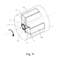
- the pole pieces 52 and 53rd by angled in the axial direction over the lateral surface of the exciter piston To extend 3 extending angled approaches 52A and 53A (see Fig. 8).
- the angle plate of the shutter 50, the center of the exciter piston. 3 For example, by means of a pin 51A pivotally mounted and by means of Torsion spring 55 in one or the other position (either open or closed) is held, that has along the lateral surface of the exciter piston 3 extending serving as flow guide surfaces approaches 52A and 53A on, which ensure that constantly a closed magnetic Circle with a small air gap to the pole pieces 48 and 49 is formed. Should this magnetic flux guide for the entire stroke position of the exciter piston. 3 be reliably ensured, so it is appropriate to overlap between the Polschuhan arrangementsn 52 A, 53 A and the pole pieces 48, 49 of the stator exciter magnet provided.
- the shutter 50 is substantially formed as one-sided hinged at articulation point 51 one-armed lever, whose one free and longer end forms the one pole piece 53, while the second pole piece 52 closer to an arcuate approach Anschddling 51 is provided.
- the magnetic flux path to that of the pole piece 52 associated pole piece 48 on the stator 47 is replaced by a on the excitation piston. 3 fixed ferromagnetic sheet metal part 62 bridged.
- the mass to be moved the shutter 50 is significantly reduced in this solution.
- Fig. 5A shows in turn, the closed valve position when energized coil 46 and Fig. 5B the by the torsion spring 55 (not shown in Figs. 5A and 5B) caused opened Valve position.
- the shutter 50 is two-armed Extended lever executed, the end-side pole pieces 52, 53 corresponding Pole shoes 48 and 49 on separate, in opposite phase by coils 46 and 46 'excited stator 47 and 47' face each other.
- FIG. 7 corresponds to that according to FIG. 6.
- the stator-side magnetic flux is closed via a yoke 65.
- the Fig. 6 shows the shutter position "valve closed” with energized coil 46th or 46 'and Fig. 7 the position "valve open” with non-energized stator and Reset by (not shown in these figures) torsion spring.
- FIGS. 9 and 10 illustrate two further advantageous variants or Embodiments for the structural design of the exciter piston. 3 passing controllable valve. Both figures show one in the body the excitation piston 3 integrated electromagnetic valve (solenoid valve) 90, the excitation current in the case of FIG. 9 by a pair of sliding rails 91, 92 is supplied as a transformer element, wherein the one grinding rail 91 in the outer jacket of the excitation piston 3 and the other sliding rail 92 in the guide tube 16 are integrated.
- the short to the electronic Control 9 excited driver 60 is effected as indicated by dotted lines via the connecting rod drive 31.
- the excitation takes place of the solenoid valve 90 via a transformer transformer 94, whose outside the guide tube 16 lying primary coil 93 a possible Has stroke of the exciter piston 3 covering axial length.
Landscapes
- Engineering & Computer Science (AREA)
- Mechanical Engineering (AREA)
- Percussive Tools And Related Accessories (AREA)
Abstract
Description
- Fig. 1
- die schematische Darstellung eines Bohr- und/oder Meisselhammers mit pneumatischem Schlagwerk, dessen Erregerkolben gemäß der Erfindung mit einem steuerbaren Ventil ausgestattet ist;
- Fig. 2
- mit Teilfiguren 2A, 2B und 2C die schematische Schnitt-Ansichtdarstellung bzw. die Seitenschnitt- und Draufsicht-Schnittdarstellung eines durch einen Pleuel angetriebenen Erregerkolbens mit einem diesen durchsetzenden Drehventil gemäß der Erfindung;
- Fig. 3
- die schematische Schnittdarstellung des Erregerkolbens mit einem Schieberkanten-Ventil;
- Fig. 4
- mit Teilfiguren 4A bzw. 4B eine erfindungsgemäße Ventillösung durch den Erregerkolben mit einem elektromagnetisch nach dem Reluktanzprinzip verschieblichen Shutter als Ventilverschlusselement bei geschlossenem Ventil (Fig. 4A) einerseits bzw. geöffnetem Ventil (Fig. 4B) andererseits;
- Fig. 5
- mit Teilfiguren 5A bzw. 5B eine andere Ausführungsform eines Magnetventils mit nach dem Prinzip des Reluktanzmotors verschwenkbarem Shutter;
- Fig. 6
- eine weitere Ausführungsvariante eines nach dem Reluktanzprinzip verschwenkbaren Shutters für eine den Erregerkolben durchsetzende Ventilbohrung im geschlossenen Zustand;
- Fig. 7
- eine gegenüber der Fig. 6 abgewandelte Ausführungsvariante mit bügelartigem Magnetjoch;
- Fig. 8
- eine isometrische Prinzipskizze für einen Shutter gemäß Fig. 4, bei der die an den freien Enden eines zweiarmigen Hebels ausgebildeten Polschuhe in Axialrichtung abgebogen und verlängert sind, um in unterschiedlichen axialen Positionen des Erregerkolbens stets einen geschlossenen und in ferromagnetischem Material geführten Magnetfluss sicherzustellen;
- Fig. 9
- die schematische Darstellung eines den Erregerkolben des elektropneumatischen Schlagwerks durchsetzenden und in diesen integrierten Solenoid-Ventils mit Stromzuführung über ein Schleifschienenpaar als Übertrager; und
- Fig. 10
- eine der Fig. 9 entsprechende Ventillösung, bei der ein transformatorischer Übertrager zur Erregung des in den Erregerkolben integrierten Ventils dient.
Claims (21)
- Vorrichtung zur variablen Einstellung der Schlagenergie eines elektropneumatischen Schlagwerks (15) in einem damit ausgerüsteten Bohr-und/oder Meisselhammer (1), dessen Erregerkolben (3) über ein von diesem erzeugtes Fluid-Druckpolster (20) auf ein Abbauwerkzeug wirkt, gekennzeichnet durch ein den Erregerkolben (3) durchsetzendes, steuerbares Ventil zur Änderung des Drucks im Fluid-Druckpolster (20).
- Einstellvorrichtung nach Anspruch 1, dadurch gekennzeichnet, dass das Ventil ein in einen den Erregerkolben (3) durchsetzenden Belüftungskanal (32) eingesetztes Drehschieberventil (Fig. 3, 2) mit einem auf der dem Druckpolster (20) abgekehrten Stirnseite des Erregerkolbens herausgeführten Betätigungsorgan (35, 37, 38) zum Verdrehen seiner Ventilspindel (34; 45) ist.
- Einstellvorrichtung nach Anspruch 2, dadurch gekennzeichnet, dass das Betätigungsorgan ein in axialer Bewegungsrichtung des Erregerkolbens längs erstrecktes Gabelelement (35) mit einer Schlitzführung (36) für einen in diese gleitend eingreifenden Mitnehmerzapfen (37) aufweist, der an einem relativ zur Axialbewegung des Erregerkolbens verdrehbaren Stellglied (38) für die Ventilbetätigung ausgebildet ist.
- Einstellvorrichtung nach Anspruch 2, dadurch gekennzeichnet, dass das Ventil ein Schieberkanten-Ventil (Fig. 3) ist, dessen den Erregerkolben axial durchsetzende drehbare Ventilspindel (45) an ihrer vorderen, dem Druckpolster zugekehrten Stirnfläche eine Schrägfläche (44) aufweist, wodurch der Belüftungskanal (32) in Abhängigkeit vom Verdrehwinkel der Ventilspindel relativ zum Erregerkolben über die Schrägfläche zur Änderung des Drucks im Fluid-Druckpolster mehr oder weniger öffenbar ist.
- Einstellvorrichtung nach Anspruch 4, dadurch gekennzeichnet, dass der Belüftungskanal (32) den Erregerkolben (3) schräg zu dessen axialer Bewegungsrichtung durchsetzt.
- Einstellvorrichtung nach Anspruch 1, dadurch gekennzeichnet, dass ein Verschlussorgan des Ventils ein elektromagnetisch steuerbarer Shutter (50) für einen den Erregerkolben (3) in Axialrichtung durchsetzenden Belüftungskanal (32) ist.
- Einstellvorrichtung nach Anspruch 6, dadurch gekennzeichnet, dass der Shutter ein nach dem Reluktanzprinzip verschwenkbar gelagertes Verschlusselement ist.
- Einstellvorrichtung nach Anspruch 7, dadurch gekennzeichnet, dass das Verschlusselement ein am Erregerkolben angelenkter Shutterverschlusshebel (50) aus ferromagnetischem Material ist, der über einen durch eine elektrische Spule (46) erregten relativ zum Erregerkolben gerätefesten Stator (47) verdrehbar ist.
- Einstellvorrichtung nach Anspruch 8, dadurch gekennzeichnet, dass an dem Shutterverschlusshebel mindestens ein magnetisches Polschuhpaar (52, 53) ausgebildet ist, dem, über Luftspalte (54, 55) getrennt, ein korrespondierendes Polschuhpaar (48, 49) am Stator (47) zugeordnet ist.
- Einstellvorrichtung nach Anspruch 9, dadurch gekennzeichnet, dass der Shutterverschlusshebel zwei gegeneinander in einem Winkel α versetzte, um einen gemeinsamen Anlenkpunkt (51) verschwenkbare Hebelarme aufweist.
- Einstellvorrichtung nach Anspruch 10, dadurch gekennzeichnet, dass der Winkel 45° ≤ a ≤ 180° beträgt.
- Einstellvorrichtung nach Anspruch 11, dadurch gekennzeichnet, dass der Winkel etwa α = 90° beträgt.
- Einstellvorrichtung nach Anspruch 11, dadurch gekennzeichnet, dass der Winkel etwa α = 180° beträgt.
- Einstellvorrichtung nach Anspruch 9, dadurch gekennzeichnet, dass ein Polschuh (53) des Polschuhpaars am dem Anlenkpunkt (51) abgekehrten freien Ende des Shutterverschlusshebels im Bereich der Mantelfläche des Erregerkolbens und der andere Polschuh an einem mit dem Erregerkolben fest verbundenen magnetischen Brückenteil (62) ausgebildet ist, das über einen weiteren, dem Anlenkpunkt zugekehrten Polschuh (52) einen geschlossenen Magnetflussweg über den Shutterhebel sicherstellt.
- Einstellvorrichtung nach einem der Ansprüche 8 bis 14, dadurch gekennzeichnet, dass der Shutterverschlusshebel als geformtes Blechteil mit in Längserstreckung der Mantelfläche des Erregerkolbens liegendem Ansatz/liegenden Ansätzen (52A, 53A) für den oder die Polschuh(e) ausgebildet ist.
- Einstellvorrichtung nach Anspruch 15, dadurch gekennzeichnet, dass sowohl die Polschuhe (48, 49) am gerätefesten Stator (47) als auch der Ansatz oder die Ansätze (52A, 53A) eine mindestens einem Teilbereich des möglichen Hubs des Erregerkolbens entsprechende axiale Länge aufweisen.
- Einstellvorrichtung nach Anspruch 7, dadurch gekennzeichnet, dass das Verschlusselement durch eine Drehfeder (55) in eine von zwei Endstellungen, d. h. "Ventil offen" oder "Ventil geschlossen" vorgespannt ist.
- Einstellvorrichtung nach Anspruch 1, dadurch gekennzeichnet, dass das Ventil ein in den Erregerkolben (3) integriertes elektromagnetisch betätigbares Ventil (90) ist.
- Einstellvorrichtung nach Anspruch 18, dadurch gekennzeichnet, dass die Zuführung des Errgerstroms für das Ventil (90) über einen zweiteiligen Übertrager erfolgt, dessen eines Teil in den Erregerkolben (3) integriert und mit diesem axial verschieblich ist, während das korrespondierende andere Teil radial außerhalb und gerätegehäusefest angeordnet ist.
- Einstellvorrichtung nach Anspruch 19, dadurch gekennzeichnet, dass das eine Teil des Übertragers eine in die Mantelfläche des Erregerkolbens (3) integrierte erste Schleifkontaktschiene (91) und das andere Teil eine in die Innenmantelfläche eines Führungsrohrs (16) integrierte und mit der ersten Schleifkontaktschiene in galvanischem Kontakt stehende zweite Schleifkontaktschiene (92) ist, deren axiale Länge so bemessen ist, dass in allen Hubpositionen des Erregerkolbens (3) der galvanische Kontakt aufrechterhalten bleibt.
- Einstellvorrichtung nach Anspruch 19, dadurch gekennzeichnet, dass der Übertrager ein transformatorischer Übertrager (94) ist, dessen Sekundärspule in den Mantel des Erregerkolbens (3) integriert ist, dessen Primärspule (94) gehäusefest und radial außerhalb des Erregerkolbenwegs angeordnet ist und eine axiale Länge aufweist, die in allen Hubpositionen des Erregerkolbens eine Erregerstromübertragung zum Ventil gewährleistet.
Priority Applications (1)
| Application Number | Priority Date | Filing Date | Title |
|---|---|---|---|
| EP20040101429 EP1584420B1 (de) | 2004-04-07 | 2004-04-07 | Bohr- und/oder Meisselhammer mit elektropneumatischem Schlagwerk und einer Vorrichtung zur variablen Einstellung der Schlagenergie |
Applications Claiming Priority (1)
| Application Number | Priority Date | Filing Date | Title |
|---|---|---|---|
| EP20040101429 EP1584420B1 (de) | 2004-04-07 | 2004-04-07 | Bohr- und/oder Meisselhammer mit elektropneumatischem Schlagwerk und einer Vorrichtung zur variablen Einstellung der Schlagenergie |
Publications (2)
| Publication Number | Publication Date |
|---|---|
| EP1584420A1 true EP1584420A1 (de) | 2005-10-12 |
| EP1584420B1 EP1584420B1 (de) | 2014-06-11 |
Family
ID=34896121
Family Applications (1)
| Application Number | Title | Priority Date | Filing Date |
|---|---|---|---|
| EP20040101429 Expired - Lifetime EP1584420B1 (de) | 2004-04-07 | 2004-04-07 | Bohr- und/oder Meisselhammer mit elektropneumatischem Schlagwerk und einer Vorrichtung zur variablen Einstellung der Schlagenergie |
Country Status (1)
| Country | Link |
|---|---|
| EP (1) | EP1584420B1 (de) |
Cited By (6)
| Publication number | Priority date | Publication date | Assignee | Title |
|---|---|---|---|---|
| DE102008005831A1 (de) | 2008-01-24 | 2009-07-30 | Schaeffler Kg | Schlagwerk für eine Werkzeugmaschine, insbesondere für eine Handwerkzeugmaschine wie einen elektrischen Bohrhammer oder einen Schlagschrauber |
| DE102009015730A1 (de) | 2009-03-31 | 2010-10-07 | Schaeffler Technologies Gmbh & Co. Kg | Schlagwerk für eine Werkzeugmaschine |
| DE102009015729A1 (de) | 2009-03-31 | 2010-10-07 | Schaeffler Technologies Gmbh & Co. Kg | Schlagwerk für eine Werkzeugmaschine |
| DE102009015732A1 (de) | 2009-03-31 | 2010-10-07 | Schaeffler Technologies Gmbh & Co. Kg | Schlagwerk für eine Werkzeugmaschine |
| CN105592986A (zh) * | 2013-10-03 | 2016-05-18 | 喜利得股份公司 | 手持工具机 |
| EP4126463A4 (de) * | 2020-04-02 | 2024-05-08 | Milwaukee Electric Tool Corporation | Elektrowerkzeug |
Families Citing this family (1)
| Publication number | Priority date | Publication date | Assignee | Title |
|---|---|---|---|---|
| EP4382254A1 (de) * | 2022-12-07 | 2024-06-12 | Hilti Aktiengesellschaft | Schlagwerk für ein handgeführtes elektrowerkzeug und handgeführtes elektrowerkzeug |
Citations (6)
| Publication number | Priority date | Publication date | Assignee | Title |
|---|---|---|---|---|
| GB942668A (en) | 1959-04-30 | 1963-11-27 | Bosch Gmbh Robert | Improvements in or relating to hammers |
| GB991533A (en) * | 1963-05-09 | 1965-05-12 | Jakob Hemmler | Improvements in percussion drills |
| DE3024715A1 (de) * | 1980-06-30 | 1982-04-22 | Hitachi Koki Co., Ltd., Tokyo | Schlagbohrmaschine |
| US4732219A (en) * | 1985-11-02 | 1988-03-22 | Hilti Aktiengesellschaft | Hammer drill with pneumatically driven percussion piston |
| EP0388383A1 (de) * | 1989-03-16 | 1990-09-19 | Atlas Copco Berema Aktiebolag | Hammermaschine |
| EP0775556A1 (de) * | 1995-11-27 | 1997-05-28 | Black & Decker Inc. | Hammermechanismus |
-
2004
- 2004-04-07 EP EP20040101429 patent/EP1584420B1/de not_active Expired - Lifetime
Patent Citations (6)
| Publication number | Priority date | Publication date | Assignee | Title |
|---|---|---|---|---|
| GB942668A (en) | 1959-04-30 | 1963-11-27 | Bosch Gmbh Robert | Improvements in or relating to hammers |
| GB991533A (en) * | 1963-05-09 | 1965-05-12 | Jakob Hemmler | Improvements in percussion drills |
| DE3024715A1 (de) * | 1980-06-30 | 1982-04-22 | Hitachi Koki Co., Ltd., Tokyo | Schlagbohrmaschine |
| US4732219A (en) * | 1985-11-02 | 1988-03-22 | Hilti Aktiengesellschaft | Hammer drill with pneumatically driven percussion piston |
| EP0388383A1 (de) * | 1989-03-16 | 1990-09-19 | Atlas Copco Berema Aktiebolag | Hammermaschine |
| EP0775556A1 (de) * | 1995-11-27 | 1997-05-28 | Black & Decker Inc. | Hammermechanismus |
Cited By (6)
| Publication number | Priority date | Publication date | Assignee | Title |
|---|---|---|---|---|
| DE102008005831A1 (de) | 2008-01-24 | 2009-07-30 | Schaeffler Kg | Schlagwerk für eine Werkzeugmaschine, insbesondere für eine Handwerkzeugmaschine wie einen elektrischen Bohrhammer oder einen Schlagschrauber |
| DE102009015730A1 (de) | 2009-03-31 | 2010-10-07 | Schaeffler Technologies Gmbh & Co. Kg | Schlagwerk für eine Werkzeugmaschine |
| DE102009015729A1 (de) | 2009-03-31 | 2010-10-07 | Schaeffler Technologies Gmbh & Co. Kg | Schlagwerk für eine Werkzeugmaschine |
| DE102009015732A1 (de) | 2009-03-31 | 2010-10-07 | Schaeffler Technologies Gmbh & Co. Kg | Schlagwerk für eine Werkzeugmaschine |
| CN105592986A (zh) * | 2013-10-03 | 2016-05-18 | 喜利得股份公司 | 手持工具机 |
| EP4126463A4 (de) * | 2020-04-02 | 2024-05-08 | Milwaukee Electric Tool Corporation | Elektrowerkzeug |
Also Published As
| Publication number | Publication date |
|---|---|
| EP1584420B1 (de) | 2014-06-11 |
Similar Documents
| Publication | Publication Date | Title |
|---|---|---|
| DE602004006900T2 (de) | Magnetisches Einschlagwerkzeug | |
| DE69903872T2 (de) | Elektromechanisches Zylinderschloss | |
| DE102004018084B3 (de) | Hammerbohrgerät | |
| EP1955823B1 (de) | Handwerkzeugmaschine mit pneumatischem Schlagwerk | |
| WO2003024672A1 (de) | Bohr- und/oder schlaghammer mit anpressdruckabhängiger leerlaufsteuerung | |
| DE19955079A1 (de) | Elektromagnetischer Antrieb | |
| DE2165066C3 (de) | ||
| DE19944294A1 (de) | Fremdkraftgetriebener Bohrhammer mit verbessertem Betriebsmodusumschalter | |
| DE102005028918A1 (de) | Bohr- und/oder Schlaghammer mit Leerlaufsteuerung | |
| WO2011000370A1 (de) | Bohrvorrichtung | |
| EP3389933B1 (de) | Schlagende handwerkzeugmaschine | |
| DE10312980B4 (de) | Bohrhammer oder Schlagbohrmaschine | |
| DE102015214301A1 (de) | Möbelstück und Stellanordnung, insbesondere für eine Lehnenverstellung | |
| EP1115933B1 (de) | Betätigungsvorrichtung | |
| DE102005000061A1 (de) | Elektrisch betriebenes Eintreibgerät | |
| EP1584420B1 (de) | Bohr- und/oder Meisselhammer mit elektropneumatischem Schlagwerk und einer Vorrichtung zur variablen Einstellung der Schlagenergie | |
| EP2871028A1 (de) | Handwerkzeugmaschine | |
| EP3389932A1 (de) | Schlagende handwerkzeugmaschine | |
| DE19860451A1 (de) | Antrieb für ein Ventil eines Verbrennungsmotors | |
| EP1697090B1 (de) | Schlagwerk für eine repetierend schlagende handwerkzeugmaschine | |
| EP1607187B1 (de) | Einrichtung zur Verbesserung des Abschaltverhaltens eines elektropneumatischen Abbaugeräts | |
| EP3389934B1 (de) | Schlagende handwerkzeugmaschine | |
| DE102016004193B4 (de) | Schlagwerkzeug | |
| EP0971160B1 (de) | Aktiv gesteuertes Ventil für einen Kolbenkompressor | |
| DE202008000318U1 (de) | Nadelverschlussdüse mit verbesserter Hebelanlenkung |
Legal Events
| Date | Code | Title | Description |
|---|---|---|---|
| PUAI | Public reference made under article 153(3) epc to a published international application that has entered the european phase |
Free format text: ORIGINAL CODE: 0009012 |
|
| AK | Designated contracting states |
Kind code of ref document: A1 Designated state(s): AT BE BG CH CY CZ DE DK EE ES FI FR GB GR HU IE IT LI LU MC NL PL PT RO SE SI SK TR |
|
| AX | Request for extension of the european patent |
Extension state: AL HR LT LV MK |
|
| 17P | Request for examination filed |
Effective date: 20060412 |
|
| AKX | Designation fees paid |
Designated state(s): CH DE FR GB LI SE |
|
| 17Q | First examination report despatched |
Effective date: 20061123 |
|
| RTI1 | Title (correction) |
Free format text: DRILLING AND/OR CHIPPING HAMMER WITH ELECTRO-PNEUMATIC PERCUSSION MECHANISM AND DEVICE FOR VARIABLE SETTING OF THE IMPACT ENERGY |
|
| GRAP | Despatch of communication of intention to grant a patent |
Free format text: ORIGINAL CODE: EPIDOSNIGR1 |
|
| RIC1 | Information provided on ipc code assigned before grant |
Ipc: B25D 17/06 20060101ALI20140204BHEP Ipc: B25D 11/12 20060101ALI20140204BHEP Ipc: B25D 11/00 20060101AFI20140204BHEP |
|
| INTG | Intention to grant announced |
Effective date: 20140306 |
|
| GRAS | Grant fee paid |
Free format text: ORIGINAL CODE: EPIDOSNIGR3 |
|
| GRAA | (expected) grant |
Free format text: ORIGINAL CODE: 0009210 |
|
| AK | Designated contracting states |
Kind code of ref document: B1 Designated state(s): CH DE FR GB LI SE |
|
| REG | Reference to a national code |
Ref country code: GB Ref legal event code: FG4D Free format text: NOT ENGLISH |
|
| REG | Reference to a national code |
Ref country code: CH Ref legal event code: EP |
|
| REG | Reference to a national code |
Ref country code: DE Ref legal event code: R096 Ref document number: 502004014640 Country of ref document: DE Effective date: 20140724 |
|
| REG | Reference to a national code |
Ref country code: SE Ref legal event code: TRGR |
|
| REG | Reference to a national code |
Ref country code: DE Ref legal event code: R097 Ref document number: 502004014640 Country of ref document: DE |
|
| PLBE | No opposition filed within time limit |
Free format text: ORIGINAL CODE: 0009261 |
|
| STAA | Information on the status of an ep patent application or granted ep patent |
Free format text: STATUS: NO OPPOSITION FILED WITHIN TIME LIMIT |
|
| 26N | No opposition filed |
Effective date: 20150312 |
|
| REG | Reference to a national code |
Ref country code: DE Ref legal event code: R097 Ref document number: 502004014640 Country of ref document: DE Effective date: 20150312 |
|
| REG | Reference to a national code |
Ref country code: FR Ref legal event code: PLFP Year of fee payment: 13 |
|
| REG | Reference to a national code |
Ref country code: FR Ref legal event code: PLFP Year of fee payment: 14 |
|
| REG | Reference to a national code |
Ref country code: FR Ref legal event code: PLFP Year of fee payment: 15 |
|
| PGFP | Annual fee paid to national office [announced via postgrant information from national office to epo] |
Ref country code: DE Payment date: 20190418 Year of fee payment: 16 |
|
| PGFP | Annual fee paid to national office [announced via postgrant information from national office to epo] |
Ref country code: FR Payment date: 20190418 Year of fee payment: 16 Ref country code: SE Payment date: 20190418 Year of fee payment: 16 |
|
| PGFP | Annual fee paid to national office [announced via postgrant information from national office to epo] |
Ref country code: CH Payment date: 20190418 Year of fee payment: 16 |
|
| PGFP | Annual fee paid to national office [announced via postgrant information from national office to epo] |
Ref country code: GB Payment date: 20190418 Year of fee payment: 16 |
|
| REG | Reference to a national code |
Ref country code: DE Ref legal event code: R119 Ref document number: 502004014640 Country of ref document: DE |
|
| REG | Reference to a national code |
Ref country code: CH Ref legal event code: PL |
|
| PG25 | Lapsed in a contracting state [announced via postgrant information from national office to epo] |
Ref country code: LI Free format text: LAPSE BECAUSE OF NON-PAYMENT OF DUE FEES Effective date: 20200430 Ref country code: DE Free format text: LAPSE BECAUSE OF NON-PAYMENT OF DUE FEES Effective date: 20201103 Ref country code: CH Free format text: LAPSE BECAUSE OF NON-PAYMENT OF DUE FEES Effective date: 20200430 Ref country code: FR Free format text: LAPSE BECAUSE OF NON-PAYMENT OF DUE FEES Effective date: 20200430 Ref country code: SE Free format text: LAPSE BECAUSE OF NON-PAYMENT OF DUE FEES Effective date: 20200408 |
|
| GBPC | Gb: european patent ceased through non-payment of renewal fee |
Effective date: 20200407 |
|
| PG25 | Lapsed in a contracting state [announced via postgrant information from national office to epo] |
Ref country code: GB Free format text: LAPSE BECAUSE OF NON-PAYMENT OF DUE FEES Effective date: 20200407 |