EP1584122B1 - Prozess zur herstellung von elektrizität und kohlendioxid - Google Patents
Prozess zur herstellung von elektrizität und kohlendioxid Download PDFInfo
- Publication number
- EP1584122B1 EP1584122B1 EP04701958A EP04701958A EP1584122B1 EP 1584122 B1 EP1584122 B1 EP 1584122B1 EP 04701958 A EP04701958 A EP 04701958A EP 04701958 A EP04701958 A EP 04701958A EP 1584122 B1 EP1584122 B1 EP 1584122B1
- Authority
- EP
- European Patent Office
- Prior art keywords
- gas
- anode
- cathode
- chamber
- carbon dioxide
- Prior art date
- Legal status (The legal status is an assumption and is not a legal conclusion. Google has not performed a legal analysis and makes no representation as to the accuracy of the status listed.)
- Expired - Lifetime
Links
- CURLTUGMZLYLDI-UHFFFAOYSA-N Carbon dioxide Chemical compound O=C=O CURLTUGMZLYLDI-UHFFFAOYSA-N 0.000 title claims abstract description 81
- 229910002092 carbon dioxide Inorganic materials 0.000 title claims abstract description 45
- 239000001569 carbon dioxide Substances 0.000 title claims abstract description 35
- 238000000034 method Methods 0.000 title claims abstract description 35
- 230000005611 electricity Effects 0.000 title claims abstract description 5
- 239000007789 gas Substances 0.000 claims abstract description 115
- 239000007800 oxidant agent Substances 0.000 claims abstract description 42
- 230000001590 oxidative effect Effects 0.000 claims abstract description 42
- IJGRMHOSHXDMSA-UHFFFAOYSA-N Atomic nitrogen Chemical compound N#N IJGRMHOSHXDMSA-UHFFFAOYSA-N 0.000 claims abstract description 34
- 239000000446 fuel Substances 0.000 claims abstract description 22
- 230000003197 catalytic effect Effects 0.000 claims abstract description 20
- 229910052757 nitrogen Inorganic materials 0.000 claims abstract description 17
- MYMOFIZGZYHOMD-UHFFFAOYSA-N Dioxygen Chemical compound O=O MYMOFIZGZYHOMD-UHFFFAOYSA-N 0.000 claims abstract description 15
- BVKZGUZCCUSVTD-UHFFFAOYSA-L Carbonate Chemical compound [O-]C([O-])=O BVKZGUZCCUSVTD-UHFFFAOYSA-L 0.000 claims abstract description 13
- 229910001882 dioxygen Inorganic materials 0.000 claims abstract description 6
- 239000011874 heated mixture Substances 0.000 claims abstract description 6
- 238000004519 manufacturing process Methods 0.000 claims abstract description 3
- 239000002737 fuel gas Substances 0.000 claims description 20
- VNWKTOKETHGBQD-UHFFFAOYSA-N methane Chemical compound C VNWKTOKETHGBQD-UHFFFAOYSA-N 0.000 claims description 18
- UGFAIRIUMAVXCW-UHFFFAOYSA-N Carbon monoxide Chemical compound [O+]#[C-] UGFAIRIUMAVXCW-UHFFFAOYSA-N 0.000 claims description 10
- 229910002091 carbon monoxide Inorganic materials 0.000 claims description 10
- 239000001257 hydrogen Substances 0.000 claims description 10
- 229910052739 hydrogen Inorganic materials 0.000 claims description 10
- UFHFLCQGNIYNRP-UHFFFAOYSA-N Hydrogen Chemical compound [H][H] UFHFLCQGNIYNRP-UHFFFAOYSA-N 0.000 claims description 9
- 239000003792 electrolyte Substances 0.000 claims description 7
- 238000006243 chemical reaction Methods 0.000 claims description 6
- XLYOFNOQVPJJNP-UHFFFAOYSA-N water Substances O XLYOFNOQVPJJNP-UHFFFAOYSA-N 0.000 claims description 6
- 239000003345 natural gas Substances 0.000 claims description 2
- QVGXLLKOCUKJST-UHFFFAOYSA-N atomic oxygen Chemical compound [O] QVGXLLKOCUKJST-UHFFFAOYSA-N 0.000 description 11
- 239000001301 oxygen Substances 0.000 description 11
- 229910052760 oxygen Inorganic materials 0.000 description 11
- 238000002407 reforming Methods 0.000 description 7
- 239000000203 mixture Substances 0.000 description 6
- 238000002485 combustion reaction Methods 0.000 description 3
- 238000001816 cooling Methods 0.000 description 3
- 239000011261 inert gas Substances 0.000 description 3
- 238000006057 reforming reaction Methods 0.000 description 3
- 238000011144 upstream manufacturing Methods 0.000 description 3
- OKTJSMMVPCPJKN-UHFFFAOYSA-N Carbon Chemical compound [C] OKTJSMMVPCPJKN-UHFFFAOYSA-N 0.000 description 2
- 229910052799 carbon Inorganic materials 0.000 description 2
- 238000003487 electrochemical reaction Methods 0.000 description 2
- 229930195733 hydrocarbon Natural products 0.000 description 2
- 150000002430 hydrocarbons Chemical class 0.000 description 2
- 238000011084 recovery Methods 0.000 description 2
- 238000000629 steam reforming Methods 0.000 description 2
- 239000004215 Carbon black (E152) Substances 0.000 description 1
- 238000010521 absorption reaction Methods 0.000 description 1
- 239000003054 catalyst Substances 0.000 description 1
- 239000003245 coal Substances 0.000 description 1
- 238000004891 communication Methods 0.000 description 1
- 238000009833 condensation Methods 0.000 description 1
- 230000005494 condensation Effects 0.000 description 1
- 239000012530 fluid Substances 0.000 description 1
- 150000002431 hydrogen Chemical class 0.000 description 1
- VUZPPFZMUPKLLV-UHFFFAOYSA-N methane;hydrate Chemical compound C.O VUZPPFZMUPKLLV-UHFFFAOYSA-N 0.000 description 1
- 238000000926 separation method Methods 0.000 description 1
- 230000009919 sequestration Effects 0.000 description 1
Images

Classifications
-
- H—ELECTRICITY
- H01—ELECTRIC ELEMENTS
- H01M—PROCESSES OR MEANS, e.g. BATTERIES, FOR THE DIRECT CONVERSION OF CHEMICAL ENERGY INTO ELECTRICAL ENERGY
- H01M8/00—Fuel cells; Manufacture thereof
- H01M8/14—Fuel cells with fused electrolytes
- H01M8/144—Fuel cells with fused electrolytes characterised by the electrolyte material
- H01M8/145—Fuel cells with fused electrolytes characterised by the electrolyte material comprising carbonates
-
- H—ELECTRICITY
- H01—ELECTRIC ELEMENTS
- H01M—PROCESSES OR MEANS, e.g. BATTERIES, FOR THE DIRECT CONVERSION OF CHEMICAL ENERGY INTO ELECTRICAL ENERGY
- H01M8/00—Fuel cells; Manufacture thereof
- H01M8/04—Auxiliary arrangements, e.g. for control of pressure or for circulation of fluids
- H01M8/04007—Auxiliary arrangements, e.g. for control of pressure or for circulation of fluids related to heat exchange
- H01M8/04014—Heat exchange using gaseous fluids; Heat exchange by combustion of reactants
- H01M8/04022—Heating by combustion
-
- H—ELECTRICITY
- H01—ELECTRIC ELEMENTS
- H01M—PROCESSES OR MEANS, e.g. BATTERIES, FOR THE DIRECT CONVERSION OF CHEMICAL ENERGY INTO ELECTRICAL ENERGY
- H01M8/00—Fuel cells; Manufacture thereof
- H01M8/04—Auxiliary arrangements, e.g. for control of pressure or for circulation of fluids
- H01M8/04082—Arrangements for control of reactant parameters, e.g. pressure or concentration
- H01M8/04089—Arrangements for control of reactant parameters, e.g. pressure or concentration of gaseous reactants
- H01M8/04097—Arrangements for control of reactant parameters, e.g. pressure or concentration of gaseous reactants with recycling of the reactants
-
- H—ELECTRICITY
- H01—ELECTRIC ELEMENTS
- H01M—PROCESSES OR MEANS, e.g. BATTERIES, FOR THE DIRECT CONVERSION OF CHEMICAL ENERGY INTO ELECTRICAL ENERGY
- H01M8/00—Fuel cells; Manufacture thereof
- H01M8/06—Combination of fuel cells with means for production of reactants or for treatment of residues
- H01M8/0662—Treatment of gaseous reactants or gaseous residues, e.g. cleaning
- H01M8/0668—Removal of carbon monoxide or carbon dioxide
-
- H—ELECTRICITY
- H01—ELECTRIC ELEMENTS
- H01M—PROCESSES OR MEANS, e.g. BATTERIES, FOR THE DIRECT CONVERSION OF CHEMICAL ENERGY INTO ELECTRICAL ENERGY
- H01M8/00—Fuel cells; Manufacture thereof
- H01M8/14—Fuel cells with fused electrolytes
- H01M2008/147—Fuel cells with molten carbonates
-
- H—ELECTRICITY
- H01—ELECTRIC ELEMENTS
- H01M—PROCESSES OR MEANS, e.g. BATTERIES, FOR THE DIRECT CONVERSION OF CHEMICAL ENERGY INTO ELECTRICAL ENERGY
- H01M2250/00—Fuel cells for particular applications; Specific features of fuel cell system
- H01M2250/40—Combination of fuel cells with other energy production systems
-
- H—ELECTRICITY
- H01—ELECTRIC ELEMENTS
- H01M—PROCESSES OR MEANS, e.g. BATTERIES, FOR THE DIRECT CONVERSION OF CHEMICAL ENERGY INTO ELECTRICAL ENERGY
- H01M8/00—Fuel cells; Manufacture thereof
- H01M8/06—Combination of fuel cells with means for production of reactants or for treatment of residues
- H01M8/0606—Combination of fuel cells with means for production of reactants or for treatment of residues with means for production of gaseous reactants
- H01M8/0612—Combination of fuel cells with means for production of reactants or for treatment of residues with means for production of gaseous reactants from carbon-containing material
- H01M8/0637—Direct internal reforming at the anode of the fuel cell
-
- Y—GENERAL TAGGING OF NEW TECHNOLOGICAL DEVELOPMENTS; GENERAL TAGGING OF CROSS-SECTIONAL TECHNOLOGIES SPANNING OVER SEVERAL SECTIONS OF THE IPC; TECHNICAL SUBJECTS COVERED BY FORMER USPC CROSS-REFERENCE ART COLLECTIONS [XRACs] AND DIGESTS
- Y02—TECHNOLOGIES OR APPLICATIONS FOR MITIGATION OR ADAPTATION AGAINST CLIMATE CHANGE
- Y02E—REDUCTION OF GREENHOUSE GAS [GHG] EMISSIONS, RELATED TO ENERGY GENERATION, TRANSMISSION OR DISTRIBUTION
- Y02E60/00—Enabling technologies; Technologies with a potential or indirect contribution to GHG emissions mitigation
- Y02E60/30—Hydrogen technology
- Y02E60/50—Fuel cells
-
- Y—GENERAL TAGGING OF NEW TECHNOLOGICAL DEVELOPMENTS; GENERAL TAGGING OF CROSS-SECTIONAL TECHNOLOGIES SPANNING OVER SEVERAL SECTIONS OF THE IPC; TECHNICAL SUBJECTS COVERED BY FORMER USPC CROSS-REFERENCE ART COLLECTIONS [XRACs] AND DIGESTS
- Y02—TECHNOLOGIES OR APPLICATIONS FOR MITIGATION OR ADAPTATION AGAINST CLIMATE CHANGE
- Y02P—CLIMATE CHANGE MITIGATION TECHNOLOGIES IN THE PRODUCTION OR PROCESSING OF GOODS
- Y02P70/00—Climate change mitigation technologies in the production process for final industrial or consumer products
- Y02P70/50—Manufacturing or production processes characterised by the final manufactured product
Definitions
- the present invention relates to a process for the generation of electricity and the production of a concentrated CO 2 stream using a molten carbonate fuel cell (MCFC).
- MCFC molten carbonate fuel cell
- Molten carbonate fuel cells comprise a plurality of fuel cell elements, each comprising an electrolyte layer sandwiched between an anode layer and a cathode layer.
- the electrolyte layer is a porous layer soaked with molten carbonate. Charge transfer through the electrolyte layer from the cathode to the anode is done by carbonate ions.
- Fuel gas which is reformed in the anode chamber or reformed fuel gas is fed to the anode chamber. If the fuel gas is methane, the following reforming reaction takes place: CH 4 + H 2 O ⁇ CO + 3 H 2 (1) Carbon dioxide and oxygen are fed to the cathode chamber.
- the cathode reaction in a molten carbonate fuel cell is: 4 CO 2 + 2 O 2 + 8e - ⁇ 4 CO 3 2- ; (2) and the anode reactions are: 3 CO 3 2- + 3 H 2 ⁇ 3 H 2 O + 3 CO 2 + 6e - (3) CO 3 2- + CO ⁇ 2 CO 2 + 2e - (4)
- the overall reaction is: CH 4 + H 2 O + 2 O 2 ⁇ 3 H 2 O + CO 2 (5)
- the anode off-gas is recycled, typically after combustion of the non-utilised hydrogen and carbon monoxide, to the cathode chamber to provide for the carbon dioxide needed at the cathode layer.
- Air is fed to the cathode chamber to provide for the oxygen needed.
- the exhaust gas of the system i.e. the cathode off-gas, comprises diluted carbon dioxide, usually in a concentration of about 3-5 % (v/v).
- Carbon dioxide in a highly concentrated form can be efficiently liquefied and subsequently used in enhanced oil recovery or the recovery of coal bed methane. Also for effective sequestration of carbon dioxide, a concentrated carbon dioxide stream is needed. Carbon dioxide concentrated to about 50 % (v/v), can usefully be applied in the food and paper industry.
- EP 418 864 A a process is described wherein carbon dioxide containing combustion exhaust gas is fed to the cathode chamber of a MCFC. A high-concentration carbon dioxide gas is recovered from the anode off-gas. In the process of EP 418 864 A, there is still a diluted carbon-dioxide containing gas stream emitted to the atmosphere, i.e. the cathode off- gas. Moreover, the anode off-gas from which carbon dioxide is to be recovered is diluted with nitrogen.
- molten carbonate fuel cell can be operated in such a way that a stream of highly concentrated carbon dioxide is produced as exhaust gas.
- the present invention relates to a process as defined in claim 1.
- cathode off-gas which is diluted with a molecular oxygen containing external oxidant stream which comprises at most 20% (v/v)of nitrogen, and oxidised anode off-gas are fed to the cathode chamber.
- the anode off-gas is catalytically oxidised with relatively pure oxygen, i.e. cathode off-gas and/or the external oxidant stream.
- the external oxidant stream which is used as oxidant in the catalytic afterburner and/or as oxidant for the cathode reaction, contains preferably at most 10% (v/v) nitrogen or other inert gases.
- the external oxidant stream may contain carbon dioxide.
- the carbon dioxide content of the external oxidant stream is not critical.
- the external oxidant stream preferably contains at least 70% (v/v) molecular oxygen, more preferably at least 80% (v/v).
- An external oxidant stream of substantially pure oxygen is most preferred.
- Such a stream may suitable be produced by techniques known in the art, for example by the removal of nitrogen from air by pressure swing absorption (PSA).
- PSA pressure swing absorption
- the amount of external molecular oxygen containing oxidant added to the process will be determined by the amount of oxygen needed to sustain the electrochemical reaction of the fuel cell and will thus depend on the oxygen concentration in the external oxidant stream.
- the fuel gas fed to the anode chamber is preferably a gaseous hydrocarbon gas such as natural gas, methane, biogas, or land-fill gas that is reformed in the anode chamber.
- a gaseous hydrocarbon gas such as natural gas, methane, biogas, or land-fill gas that is reformed in the anode chamber.
- Reference to reforming is to the reaction of the fuel with steam to form carbon monoxide and hydrogen, such as given by equation (1) for methane.
- An advantage of reforming in the anode chamber or internal reforming is that the heat produced by the charge transfer in the electrolyte layer can then be directly used for the endothermic reforming reaction. Reforming in the anode chamber is typically achieved by placing an additional Ni-containing reforming catalyst in the anode chamber.
- the fuel contains substantial amounts of C 2 + hydrocarbons
- it is preferred that the fuel is pre-reformed before entering the anode chamber.
- a hydrocarbonaceous fuel is converted by steam reforming into a carbon monoxide and hydrogen containing gas upstream of the anode chamber.
- the carbon monoxide and hydrogen containing gas is then fed to the anode chamber as fuel gas. Reforming upstream of the anode chamber may be performed inside or outside the fuel cell.
- the steam needed for the reforming reaction may be provided by an external source, but is preferably provided by the anode off-gas.
- part of the anode off-gas is fed to the reformer or to the anode chamber if reforming takes place inside the anode chamber.
- 35 to 90 % (v/v) of the anode-off gas is recycled to the reformer or the anode chamber, more preferably 50 to 80 % (v/v).
- the fuel gas preferably contains less than 20% (v/v) of nitrogen or other inert gases, more preferably less than 10% (v/v). Most preferably, the fuel gas contains substantially no nitrogen.
- the fuel gas may contain a substantial amount of carbon dioxide, for example up to 70% (v/v).
- the anode off-gas is at least partly fed to a catalytic afterburner. If not all of the anode off-gas is fed to the afterburner, the remainder is fed to the anode chamber either directly or indirectly via a steam reformer upstream and in fluid communication with the anode chamber for the purpose of providing the steam needed for the steam reforming reaction as explained hereinabove.
- the unconverted carbon monoxide and hydrogen in the anode off-gas are oxidised.
- the amount of oxidant fed to the catalytic afterburner is preferably the stoichiometric amount needed for oxidising the hydrogen and carbon monoxide.
- an oxidised anode off-gas containing carbon dioxide, steam and substantially no oxygen is obtained.
- the oxidant used in the catalytic afterburner might be part of the cathode off-gas, part of the external oxidant stream comprising at most 20% v/v of nitrogen or a combination of both.
- the oxidised anode off-gas is brought into heat exchange contact with the remainder of the cathode off-gas and the remainder of the external oxidant stream to obtain cooled anode off-gas and a heated mixture of cathode off-gas and external oxidant, which are both fed to the cathode chamber as the cathode inlet gas.
- the heat exchange contact serves to bring the cathode inlet gas to the appropriate cathode inlet temperature.
- the cathode inlet gas will provide for cooling of the fuel cell, i.e. of the stack of fuel cell elements each containing an electrolyte layer sandwiched between an anode layer and a cathode layer. Therefore, the temperature of the cathode inlet gas will be lower than the temperature of the cathode off-gas.
- the cathode off-gas is cooled before being brought in heat-exchange contact with the hot oxidised anode off-gas.
- the cathode inlet gas flow is higher than the flow that contains the stoichiometric amount of oxygen needed to maintain the electrochemical reaction.
- the cathode flow is 3-6 times the stoichiometric flow.
- Cooled anode off-gas and the heated mixture of cathode off-gas and external oxidant are fed to the cathode chamber until a set point in carbon dioxide concentration at the cathode chamber outlet of in the range of from 5 to 40 % (v/v) is reached.
- the amount of withdrawn anode off-gas is such that the amount of carbon in the withdrawn gas is equal to the amount of carbon in the fuel gas fed to the anode chamber.
- the carbon dioxide concentration at the outlet of the cathode chamber is kept constant at the set point.
- the set point in carbon dioxide concentration at the cathode chamber outlet should be chosen such that the efficiency and life time requirements of the fuel cell are sufficiently met.
- the set point is in the range of from 10 to 30 % (v/v).
- the withdrawn anode off-gas comprises mainly carbon dioxide and steam. If there was nitrogen present in the external oxidant stream or in the fuel gas fed to the anode chamber, the withdrawn anode off-gas will also comprise nitrogen. In the preferred case, wherein substantially pure oxygen is used as the external oxidant and nitrogen-free fuel gas is fed to the anode, the withdrawn anode off-gas consists substantially of carbon dioxide and steam.
- a concentrated carbon dioxide stream can be obtained by further cooling the withdrawn anode off-gas to a temperature at which the steam condenses. Water can thus be easily separated from the withdrawn anode off-gas.
- Figure 1 shows a conventional process for operating a molten carbonate fuel cell.
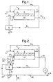
- Figure 2 shows a process according to the invention wherein a mixture of cathode off-gas and external oxidant is used as oxidant for the catalytic afterburner.
- Figure 3 shows a process according to the invention wherein only cathode off-gas is used as oxidant for the catalytic afterburner.
- Figure 4 shows a process according to the invention wherein only external oxidant is used as oxidant for the catalytic afterburner.
- Figure 1 is shown part of a molten carbonate fuel cell 1 comprising an element 2 of an electrolyte layer sandwiched between an anode layer and a cathode layer.
- Fuel gas is fed to anode chamber 5 via line 6.
- the anode off-gas is discharged from anode chamber 5 via line 7.
- the main part of the anode off-gas is led via line 8 to catalytic afterburner 9.
- Air is fed to catalytic after burner 9 via line 10.
- the remaining carbon monoxide and hydrogen in the anode off-gas is oxidised in catalytic afterburner 9.
- the oxidised anode off-gas and air are fed via lines 11 and 12, respectively, to cathode chamber 13.
- Part of the anode off-gas is recycled to anode chamber 5 via line 14.
- Cathode off-gas is discharged from cathode chamber 13 via line 15.
- FIG. 2 is shown part of a molten carbonate fuel cell 1 operated according to a process of the invention.
- the cathode off-gas is led via line 16 to heat exchanger 17, wherein it is cooled to ambient temperature. Water is thus condensed from the cathode off-gas and withdrawn via line 18.
- Substantially pure oxygen from a PSA unit (not shown) is fed via line 19 to the cooled cathode off-gas in line 20, thus obtaining a mixture of cathode off-gas and oxygen.
- the amount of the mixture to provide for the amount of oxygen needed for combustion of the unconverted carbon monoxide and hydrogen in the anode off-gas is fed via valve 21 and line 22 to catalytic afterburner 9.
- FIG 3 is shown part of a molten carbonate fuel cell 1 operated according to a process of the invention.
- the process is similar to that shown in Figure 2, but now a substantially pure oxygen stream is fed to the cooled cathode off-gas in line 23.
- the external oxidant stream bypasses catalytic afterburner 9.
- the oxidant fed to catalytic afterburner 9 via line 22 is cathode off-gas only.
- FIG 4 is shown part of a molten carbonate fuel cell 1 operated according to a process of the invention.
- the process is similar to that shown in Figures 2 and 3, but now all of the cooled cathode off-gas is led from heat exchanger 17 to heat exchanger 24 via line 20.
- the oxidant for catalytic afterburner 9 is substantially pure oxygen which is fed to afterburner 9 via valve 30 and line 31. The remainder of the substantially pure oxygen stream is fed to line 20 via line 32.
- 1.0 NL/s of fresh methane is supplied via line 6 to anode chamber 5 and a stream of 19.7 NL/s containing 64 % (v/v) O 2 , 29 % (v/v) CO 2 and 7 % (v/v)O 2 and having a temperature of 600 °C is supplied to cathode chamber 13 via lines 26 and 27.
- 25.6 NL/s anode off-gas having a temperature of 675 °C and containing 63 % (v/v) CO 2 , 27 % (v/v) H 2 O, 4 % (v/v) H 2 and 5 % (v/v) CO is discharged from anode chamber 5 via line 7.
- NL/s of the anode off-gas is recycled to anode chamber 5 via line 14, 6.4 NL/s of the anode off-gas is fed to catalytic afterburner 9 via line 8.
- the anode inlet temperature is 600 °C.
- a stream of 14.6 NL/s of cathode off-gas having a temperature of 675 °C and containing 75 % (v/v) O 2 , 15 % (v/v) CO 2 and 10 % (v/v) H 2 O is discharged from cathode chamber 13 via line 16 and cooled to room temperature in heat exchange 17.
- 1.5 NL/s of water is separated from the cathode off-gas via line 18.
- NL/s The remainder of the oxidised anode off-gas and the heated oxidant make up the cathode inlet stream of 19.7 NL/s.
- Reference herein to NL/s is to litres at standard temperature and pressure conditions (STP; 0 °C and 1 atm.) per second.
Landscapes
- Chemical & Material Sciences (AREA)
- Engineering & Computer Science (AREA)
- Life Sciences & Earth Sciences (AREA)
- Sustainable Development (AREA)
- Chemical Kinetics & Catalysis (AREA)
- Sustainable Energy (AREA)
- Manufacturing & Machinery (AREA)
- Electrochemistry (AREA)
- General Chemical & Material Sciences (AREA)
- Combustion & Propulsion (AREA)
- Fuel Cell (AREA)
- Carbon And Carbon Compounds (AREA)
- Electric Double-Layer Capacitors Or The Like (AREA)
Claims (9)
- Verfahren zur Erzeugung von elektrischem Strom und zur Produktion von einem konzentrierten Kohlendioxidstrom unter Verwendung einer Karbonatschmelze-Brennstoffzelle, wobei die Brennstoffzelle einen Elektrolyten als Sandwich-Schicht zwischen einer Anode und einer Kathode, eine Anodenkammer und eine Kathodenkammer umfaßt, worin- ein Brennstoff-Gas in die Anodenkammer eingespeist wird und ein Kathodeneinlaßgas, umfassend Kohlendioxid und molekularen Sauerstoff, in die Kathodenkammer eingespeist wird,- die Anoden- und Kathodenreaktionen ablaufen gelassen werden, um elektrischen Strom, ein Anodenabgas und ein Kathodenabgas zu erzeugen,- das Anodenabgas zumindest teilweise in einen katalytischen Nachbrenner eingespeist wird, worin es mit einem Oxidationsmittel oxidiert wird, um ein oxidiertes Anodenabgas zu erhalten,- der Rest des Anodenabgases in die Anodenkammer zurückgeführt wird,dadurch gekennzeichnet, daß:- das Oxidationsmittel aus einem Teil des Kathodenabgases und/oder aus einem Teil eines molekularen Sauerstoffenthaltenden externen Oxidationsmittelstromes besteht, welcher externe Oxidationsmittelstrom höchstens 20% (Vol./Vol.) Stickstoff umfaßt;- das oxidierte Anodenabgas mit dem Rest des Kathodenabgases und dem Rest des externen Oxidationsmittelstromes in Wärmeaustauschkontakt gebracht wird, um ein abgekühltes Anodenabgas und eine erhitzte Mischung von Kathodenabgas und externem Oxidationsmittel zu erhalten;- das Kathodenabgas, bevor es mit dem oxidierten Anodenabgas in Wärmeaustauschkontakt gebracht wird, gekühlt wird;- das abgekühlte Anodenabgas und die erhitzte Mischung von Kathodenabgas und externem Oxidationsmittel als Kathodeneinlaß-Gas in die Kathodenkammer eingespeist werden;- sobald ein Sollwert der Kohlendioxidkonzentration am Auslaß der Kathodenkammer im Bereich von 5 bis 40% (Vol./Vol.) erreicht wird, ein Teil des gekühlten Anodenabgases aus dem Verfahren entfernt wird.
- Verfahren nach Anspruch 1, worin das entfernte Anodenabgas weiter abgekühlt wird, um daraus Wasser abzutrennen und einen konzentrierten Kohlendioxidstrom zu erhalten.
- Verfahren nach Anspruch 1 oder 2, worin das Brennstoff-Gas ein Gas auf Kohlenwasserstoffbasis ist und worin das Brennstoff-Gas in der Anodenkammer in ein Kohlenmonoxid und Wasserstoff enthaltendes Gas umgewandelt wird.
- Verfahren nach Anspruch 3, worin nur ein Teil des Anodenabgases in den katalytischen Nachbrenner eingespeist wird und der Rest in die Anodenkammer zurückgeführt wird, bevorzugt 35 bis 90% (Vol./Vol.) des Anodenabgases in die Anodenkammer zurückgeführt werden, stärker bevorzugt 50 bis 80% (Vol./Vol.).
- Verfahren nach Anspruch 3 oder 4, worin das Brennstoff-Gas Erdgas, Methan, Biogas oder Deponiegas ist.
- Verfahren nach Anspruch 1 oder 2, worin das Brennstoff-Gas ein Reformerabstrom ist, umfassend Wasserstoff und Kohlenmonoxid.
- Verfahren nach einem der vorstehenden Ansprüche, worin das Brennstoff-Gas höchstens 25% (Vol./Vol.) Stickstoff, bevorzugt höchstens 15% (Vol./Vol.) Stickstoff, stärker bevorzugt höchstens 10% (Vol./Vol.) Stickstoff, am stärksten bevorzugt im wesentlichen keinen Stickstoff, enthält.
- Verfahren nach einem der vorstehenden Ansprüche, worin der Sollwert der Kohlendioxidkonzentration am Auslaß der Kathodenkammer im Bereich von 10 bis 30% (Vol./Vol.) liegt.
- Verfahren nach einem der vorstehenden Ansprüche, worin der externe Oxidationsmittelstrom höchstens 10% (Vol./Vol.) Stickstoff umfaßt, bevorzugt im wesentlichen reiner Sauerstoff ist.
Priority Applications (1)
| Application Number | Priority Date | Filing Date | Title |
|---|---|---|---|
| EP04701958A EP1584122B1 (de) | 2003-01-14 | 2004-01-14 | Prozess zur herstellung von elektrizität und kohlendioxid |
Applications Claiming Priority (4)
| Application Number | Priority Date | Filing Date | Title |
|---|---|---|---|
| EP03250229 | 2003-01-14 | ||
| EP03250229 | 2003-01-14 | ||
| EP04701958A EP1584122B1 (de) | 2003-01-14 | 2004-01-14 | Prozess zur herstellung von elektrizität und kohlendioxid |
| PCT/EP2004/050016 WO2004064220A2 (en) | 2003-01-14 | 2004-01-14 | Process for generating electricity and concentrated carbon dioxide |
Publications (2)
| Publication Number | Publication Date |
|---|---|
| EP1584122A2 EP1584122A2 (de) | 2005-10-12 |
| EP1584122B1 true EP1584122B1 (de) | 2007-03-14 |
Family
ID=32695659
Family Applications (1)
| Application Number | Title | Priority Date | Filing Date |
|---|---|---|---|
| EP04701958A Expired - Lifetime EP1584122B1 (de) | 2003-01-14 | 2004-01-14 | Prozess zur herstellung von elektrizität und kohlendioxid |
Country Status (8)
| Country | Link |
|---|---|
| US (1) | US8003264B2 (de) |
| EP (1) | EP1584122B1 (de) |
| JP (1) | JP4800919B2 (de) |
| AT (1) | ATE357062T1 (de) |
| CA (1) | CA2513205C (de) |
| DE (1) | DE602004005306T2 (de) |
| NO (1) | NO20053812D0 (de) |
| WO (1) | WO2004064220A2 (de) |
Families Citing this family (32)
| Publication number | Priority date | Publication date | Assignee | Title |
|---|---|---|---|---|
| US7326482B2 (en) * | 2004-03-04 | 2008-02-05 | Delphi Technologies, Inc. | Apparatus and method for operation of a high temperature fuel cell system using recycled anode exhaust |
| US7674538B2 (en) | 2004-03-04 | 2010-03-09 | Delphi Technologies, Inc. | Apparatus and method for high efficiency operation of a high temperature fuel cell system |
| US20060051629A1 (en) * | 2004-09-03 | 2006-03-09 | Limbeck Uwe M | Fuel cell system and shutdown method for a fuel cell system |
| FI121444B (fi) * | 2005-01-03 | 2010-11-15 | Waertsilae Finland Oy | Järjestely ja menetelmä polttokennolaitteistossa |
| KR100802283B1 (ko) * | 2006-09-01 | 2008-02-11 | 두산중공업 주식회사 | 연료극 배출가스의 재순환 방식을 적용한 연료전지 발전장치 |
| US7799473B2 (en) * | 2006-12-27 | 2010-09-21 | Gm Global Technology Operations, Inc. | Anode recirculation for a parallel dual stack fuel cell system |
| JP2009076273A (ja) * | 2007-09-19 | 2009-04-09 | Nippon Telegr & Teleph Corp <Ntt> | 燃料電池システム |
| BR112015020949A2 (pt) | 2013-03-15 | 2017-07-18 | Exxonmobil Res & Eng Co | geração de energia integrada usando células de combustível de carbonato fundido |
| US9077008B2 (en) | 2013-03-15 | 2015-07-07 | Exxonmobil Research And Engineering Company | Integrated power generation and chemical production using fuel cells |
| US9755258B2 (en) | 2013-09-30 | 2017-09-05 | Exxonmobil Research And Engineering Company | Integrated power generation and chemical production using solid oxide fuel cells |
| US9819042B2 (en) | 2013-09-30 | 2017-11-14 | Exxonmobil Research And Engineering Company | Fuel cell integration within a heat recovery steam generator |
| US9556753B2 (en) | 2013-09-30 | 2017-01-31 | Exxonmobil Research And Engineering Company | Power generation and CO2 capture with turbines in series |
| GB201501491D0 (en) * | 2015-01-29 | 2015-03-18 | Lg Fuel Cell Systems Inc | Method and apparatus for thermal control in a fuel cell |
| US10787891B2 (en) * | 2015-10-08 | 2020-09-29 | 1304338 Alberta Ltd. | Method of producing heavy oil using a fuel cell |
| CA2914070C (en) | 2015-12-07 | 2023-08-01 | 1304338 Alberta Ltd. | Upgrading oil using supercritical fluids |
| CA2920656C (en) | 2016-02-11 | 2018-03-06 | 1304342 Alberta Ltd. | Method of extracting coal bed methane using carbon dioxide |
| CA2997634A1 (en) | 2018-03-07 | 2019-09-07 | 1304342 Alberta Ltd. | Production of petrochemical feedstocks and products using a fuel cell |
| WO2020112804A1 (en) | 2018-11-30 | 2020-06-04 | Exxonmobil Research And Engineering Company | Cathode collector structures for molten carbonate fuel cell |
| US11211621B2 (en) | 2018-11-30 | 2021-12-28 | Exxonmobil Research And Engineering Company | Regeneration of molten carbonate fuel cells for deep CO2 capture |
| WO2020112774A1 (en) | 2018-11-30 | 2020-06-04 | Exxonmobil Research And Engineering Company | Elevated pressure operation of molten carbonate fuel cells with enhanced co2 utilization |
| AU2019388977B2 (en) | 2018-11-30 | 2025-01-30 | ExxonMobil Technology and Engineering Company | Flow field baffle for molten carbonate fuel cell cathode |
| WO2020112806A1 (en) | 2018-11-30 | 2020-06-04 | Exxonmobil Research And Engineering Company | Layered cathode for molten carbonate fuel cell |
| WO2020112812A1 (en) | 2018-11-30 | 2020-06-04 | Exxonmobil Research And Engineering Company | Operation of molten carbonate fuel cells with enhanced co 2 utilization |
| US11476486B2 (en) | 2018-11-30 | 2022-10-18 | ExxonMobil Technology and Engineering Company | Fuel cell staging for molten carbonate fuel cells |
| US11742508B2 (en) | 2018-11-30 | 2023-08-29 | ExxonMobil Technology and Engineering Company | Reforming catalyst pattern for fuel cell operated with enhanced CO2 utilization |
| US12334607B2 (en) | 2019-11-26 | 2025-06-17 | ExxonMobil Technology and Engineering Company | Fuel cell assembly with external manifold for parallel flow |
| US11335937B2 (en) | 2019-11-26 | 2022-05-17 | Exxonmobil Research And Engineering Company | Operation of molten carbonate fuel cells with high electrolyte fill level |
| WO2021107933A1 (en) | 2019-11-26 | 2021-06-03 | Exxonmobil Research And Engineering Company | Fuel cell module assembly and systems using same |
| CA3069717A1 (en) | 2020-01-24 | 2021-07-24 | 1304338 Alberta Ltd. | Method and system to produce hydrocarbon feedstocks |
| US11978931B2 (en) | 2021-02-11 | 2024-05-07 | ExxonMobil Technology and Engineering Company | Flow baffle for molten carbonate fuel cell |
| US11955674B1 (en) | 2023-03-07 | 2024-04-09 | Chevron Phillips Chemical Company Lp | Use of a fuel cell to decarbonize a hydrocarbon cracking system |
| GB2632689A (en) * | 2023-08-17 | 2025-02-19 | Siemens Energy Global Gmbh & Co Kg | Method for operating a solid oxide fuel cell system and a solid oxide fuel cell system |
Family Cites Families (13)
| Publication number | Priority date | Publication date | Assignee | Title |
|---|---|---|---|---|
| US4810595A (en) * | 1987-01-09 | 1989-03-07 | New Energy Development Organization | Molten carbonate fuel cell, and its operation control method |
| JPH02172159A (ja) | 1988-12-24 | 1990-07-03 | Ishikawajima Harima Heavy Ind Co Ltd | 溶融炭酸塩型燃料電池発電方法及び装置 |
| US4917971A (en) | 1989-03-03 | 1990-04-17 | Energy Research Corporation | Internal reforming fuel cell system requiring no recirculated cooling and providing a high fuel process gas utilization |
| DE3932217A1 (de) | 1989-04-25 | 1990-10-31 | Linde Ag | Verfahren fuer den betrieb von hochtemperatur-brennstoffzellen |
| US5232793A (en) | 1989-09-19 | 1993-08-03 | Ishikawajima-Harima Heavy Industries Co., Ltd. | Method of and apparatus for utilizing and recovering co2 in combustion exhaust gas |
| US5084363A (en) * | 1990-01-10 | 1992-01-28 | International Fuel Cells Corp. | Molten carbonate fuel cell power plant |
| JP2819730B2 (ja) * | 1990-02-15 | 1998-11-05 | 石川島播磨重工業株式会社 | 溶融炭酸塩型燃料電池の運転方法 |
| JP2517799B2 (ja) * | 1991-04-01 | 1996-07-24 | 株式会社日立製作所 | 電気化学的排ガス処理システム |
| US5449568A (en) * | 1993-10-28 | 1995-09-12 | The United States Of America As Represented By The United States Department Of Energy | Indirect-fired gas turbine bottomed with fuel cell |
| JPH1126004A (ja) * | 1997-07-02 | 1999-01-29 | Toshiba Corp | 発電システム |
| CA2325072A1 (en) * | 2000-10-30 | 2002-04-30 | Questair Technologies Inc. | Gas separation for molten carbonate fuel cell |
| RU2280925C2 (ru) * | 2000-10-30 | 2006-07-27 | Квестэйр Текнолоджиз Инк. | Разделение газов с высоким энергетическим кпд для топливных элементов |
| GB0103779D0 (en) | 2001-02-15 | 2001-04-04 | Clean Carbon Energy As | Fuel cells |
-
2004
- 2004-01-14 EP EP04701958A patent/EP1584122B1/de not_active Expired - Lifetime
- 2004-01-14 WO PCT/EP2004/050016 patent/WO2004064220A2/en not_active Ceased
- 2004-01-14 AT AT04701958T patent/ATE357062T1/de not_active IP Right Cessation
- 2004-01-14 CA CA2513205A patent/CA2513205C/en not_active Expired - Fee Related
- 2004-01-14 DE DE602004005306T patent/DE602004005306T2/de not_active Expired - Lifetime
- 2004-01-14 JP JP2006500113A patent/JP4800919B2/ja not_active Expired - Fee Related
- 2004-01-14 US US10/542,154 patent/US8003264B2/en not_active Expired - Fee Related
-
2005
- 2005-08-12 NO NO20053812A patent/NO20053812D0/no not_active Application Discontinuation
Also Published As
| Publication number | Publication date |
|---|---|
| ATE357062T1 (de) | 2007-04-15 |
| US20060159967A1 (en) | 2006-07-20 |
| JP2006515106A (ja) | 2006-05-18 |
| JP4800919B2 (ja) | 2011-10-26 |
| DE602004005306D1 (de) | 2007-04-26 |
| NO20053812L (no) | 2005-08-12 |
| CA2513205C (en) | 2013-01-08 |
| US8003264B2 (en) | 2011-08-23 |
| CA2513205A1 (en) | 2004-07-29 |
| NO20053812D0 (no) | 2005-08-12 |
| WO2004064220A2 (en) | 2004-07-29 |
| WO2004064220A3 (en) | 2004-09-16 |
| EP1584122A2 (de) | 2005-10-12 |
| DE602004005306T2 (de) | 2007-12-20 |
Similar Documents
| Publication | Publication Date | Title |
|---|---|---|
| EP1584122B1 (de) | Prozess zur herstellung von elektrizität und kohlendioxid | |
| US20260100390A1 (en) | Reformer-electrolyzer-purifier (rep) assembly for hydrogen production, systems incorporating same and method of producing hydrogen | |
| US6878362B2 (en) | Fuel processor apparatus and method based on autothermal cyclic reforming | |
| AU760235B2 (en) | Solid oxide fuel cell which operates with an excess of fuel | |
| EP1790027B1 (de) | Integrierte hocheffiziente fossilbrennstoff-energieerzeugungsanlage/brennstoffzellensystem mit co2-emissionsminderung | |
| US20050123810A1 (en) | System and method for co-production of hydrogen and electrical energy | |
| NO323025B1 (no) | Produksjon av elektrisk energi ut fra naturgass ved benyttelse av en fastoksid-brenselcelle | |
| JPH07315801A (ja) | 高純度水素製造システム、高純度水素の製造方法及び燃料電池システム | |
| US6551732B1 (en) | Use of fuel cell cathode effluent in a fuel reformer to produce hydrogen for the fuel cell anode | |
| AU2003261675B2 (en) | Shift membrane burner/fuel cell combination | |
| US20130130134A1 (en) | Solid oxide fuel cell steam reforming power system | |
| US20060102493A1 (en) | Enrichment of oxygen for the production of hydrogen from hydrocarbons with co2 capture | |
| CN116454331B (zh) | 一种用于碳捕捉的固体氧化物燃料电池热平衡系统及方法 | |
| KR100646985B1 (ko) | 평판형 연료개질 시스템 및 이를 구비한 연료전지 시스템 | |
| KR102691661B1 (ko) | 공기 분리 유닛을 구비하는 sofc-ccs 하이브리드 시스템 | |
| JPH07130382A (ja) | 内部改質燃料電池 | |
| WO2007021174A1 (en) | Method for the integrated operation of a fuel cell and an air separator |
Legal Events
| Date | Code | Title | Description |
|---|---|---|---|
| PUAI | Public reference made under article 153(3) epc to a published international application that has entered the european phase |
Free format text: ORIGINAL CODE: 0009012 |
|
| 17P | Request for examination filed |
Effective date: 20050624 |
|
| AK | Designated contracting states |
Kind code of ref document: A2 Designated state(s): AT BE BG CH CY CZ DE DK EE ES FI FR GB GR HU IE IT LI LU MC NL PT RO SE SI SK TR |
|
| AX | Request for extension of the european patent |
Extension state: AL LT LV MK |
|
| DAX | Request for extension of the european patent (deleted) | ||
| GRAP | Despatch of communication of intention to grant a patent |
Free format text: ORIGINAL CODE: EPIDOSNIGR1 |
|
| GRAS | Grant fee paid |
Free format text: ORIGINAL CODE: EPIDOSNIGR3 |
|
| GRAA | (expected) grant |
Free format text: ORIGINAL CODE: 0009210 |
|
| AK | Designated contracting states |
Kind code of ref document: B1 Designated state(s): AT BE BG CH CY CZ DE DK EE ES FI FR GB GR HU IE IT LI LU MC NL PT RO SE SI SK TR |
|
| PG25 | Lapsed in a contracting state [announced via postgrant information from national office to epo] |
Ref country code: CH Free format text: LAPSE BECAUSE OF FAILURE TO SUBMIT A TRANSLATION OF THE DESCRIPTION OR TO PAY THE FEE WITHIN THE PRESCRIBED TIME-LIMIT Effective date: 20070314 Ref country code: NL Free format text: LAPSE BECAUSE OF FAILURE TO SUBMIT A TRANSLATION OF THE DESCRIPTION OR TO PAY THE FEE WITHIN THE PRESCRIBED TIME-LIMIT Effective date: 20070314 Ref country code: SI Free format text: LAPSE BECAUSE OF FAILURE TO SUBMIT A TRANSLATION OF THE DESCRIPTION OR TO PAY THE FEE WITHIN THE PRESCRIBED TIME-LIMIT Effective date: 20070314 Ref country code: AT Free format text: LAPSE BECAUSE OF FAILURE TO SUBMIT A TRANSLATION OF THE DESCRIPTION OR TO PAY THE FEE WITHIN THE PRESCRIBED TIME-LIMIT Effective date: 20070314 Ref country code: BE Free format text: LAPSE BECAUSE OF FAILURE TO SUBMIT A TRANSLATION OF THE DESCRIPTION OR TO PAY THE FEE WITHIN THE PRESCRIBED TIME-LIMIT Effective date: 20070314 Ref country code: LI Free format text: LAPSE BECAUSE OF FAILURE TO SUBMIT A TRANSLATION OF THE DESCRIPTION OR TO PAY THE FEE WITHIN THE PRESCRIBED TIME-LIMIT Effective date: 20070314 Ref country code: FI Free format text: LAPSE BECAUSE OF FAILURE TO SUBMIT A TRANSLATION OF THE DESCRIPTION OR TO PAY THE FEE WITHIN THE PRESCRIBED TIME-LIMIT Effective date: 20070314 |
|
| REG | Reference to a national code |
Ref country code: GB Ref legal event code: FG4D |
|
| REG | Reference to a national code |
Ref country code: CH Ref legal event code: EP |
|
| REF | Corresponds to: |
Ref document number: 602004005306 Country of ref document: DE Date of ref document: 20070426 Kind code of ref document: P |
|
| REG | Reference to a national code |
Ref country code: IE Ref legal event code: FG4D |
|
| PG25 | Lapsed in a contracting state [announced via postgrant information from national office to epo] |
Ref country code: SE Free format text: LAPSE BECAUSE OF FAILURE TO SUBMIT A TRANSLATION OF THE DESCRIPTION OR TO PAY THE FEE WITHIN THE PRESCRIBED TIME-LIMIT Effective date: 20070614 |
|
| PG25 | Lapsed in a contracting state [announced via postgrant information from national office to epo] |
Ref country code: ES Free format text: LAPSE BECAUSE OF FAILURE TO SUBMIT A TRANSLATION OF THE DESCRIPTION OR TO PAY THE FEE WITHIN THE PRESCRIBED TIME-LIMIT Effective date: 20070625 |
|
| PG25 | Lapsed in a contracting state [announced via postgrant information from national office to epo] |
Ref country code: PT Free format text: LAPSE BECAUSE OF FAILURE TO SUBMIT A TRANSLATION OF THE DESCRIPTION OR TO PAY THE FEE WITHIN THE PRESCRIBED TIME-LIMIT Effective date: 20070814 |
|
| ET | Fr: translation filed | ||
| NLV1 | Nl: lapsed or annulled due to failure to fulfill the requirements of art. 29p and 29m of the patents act | ||
| REG | Reference to a national code |
Ref country code: CH Ref legal event code: PL |
|
| PG25 | Lapsed in a contracting state [announced via postgrant information from national office to epo] |
Ref country code: SK Free format text: LAPSE BECAUSE OF FAILURE TO SUBMIT A TRANSLATION OF THE DESCRIPTION OR TO PAY THE FEE WITHIN THE PRESCRIBED TIME-LIMIT Effective date: 20070314 |
|
| PG25 | Lapsed in a contracting state [announced via postgrant information from national office to epo] |
Ref country code: CZ Free format text: LAPSE BECAUSE OF FAILURE TO SUBMIT A TRANSLATION OF THE DESCRIPTION OR TO PAY THE FEE WITHIN THE PRESCRIBED TIME-LIMIT Effective date: 20070314 Ref country code: RO Free format text: LAPSE BECAUSE OF FAILURE TO SUBMIT A TRANSLATION OF THE DESCRIPTION OR TO PAY THE FEE WITHIN THE PRESCRIBED TIME-LIMIT Effective date: 20070314 |
|
| PLBE | No opposition filed within time limit |
Free format text: ORIGINAL CODE: 0009261 |
|
| STAA | Information on the status of an ep patent application or granted ep patent |
Free format text: STATUS: NO OPPOSITION FILED WITHIN TIME LIMIT |
|
| PG25 | Lapsed in a contracting state [announced via postgrant information from national office to epo] |
Ref country code: DK Free format text: LAPSE BECAUSE OF FAILURE TO SUBMIT A TRANSLATION OF THE DESCRIPTION OR TO PAY THE FEE WITHIN THE PRESCRIBED TIME-LIMIT Effective date: 20070314 |
|
| 26N | No opposition filed |
Effective date: 20071217 |
|
| PG25 | Lapsed in a contracting state [announced via postgrant information from national office to epo] |
Ref country code: GR Free format text: LAPSE BECAUSE OF FAILURE TO SUBMIT A TRANSLATION OF THE DESCRIPTION OR TO PAY THE FEE WITHIN THE PRESCRIBED TIME-LIMIT Effective date: 20070615 |
|
| PG25 | Lapsed in a contracting state [announced via postgrant information from national office to epo] |
Ref country code: MC Free format text: LAPSE BECAUSE OF NON-PAYMENT OF DUE FEES Effective date: 20080131 |
|
| PG25 | Lapsed in a contracting state [announced via postgrant information from national office to epo] |
Ref country code: IE Free format text: LAPSE BECAUSE OF NON-PAYMENT OF DUE FEES Effective date: 20080114 Ref country code: EE Free format text: LAPSE BECAUSE OF FAILURE TO SUBMIT A TRANSLATION OF THE DESCRIPTION OR TO PAY THE FEE WITHIN THE PRESCRIBED TIME-LIMIT Effective date: 20070314 |
|
| PG25 | Lapsed in a contracting state [announced via postgrant information from national office to epo] |
Ref country code: CY Free format text: LAPSE BECAUSE OF FAILURE TO SUBMIT A TRANSLATION OF THE DESCRIPTION OR TO PAY THE FEE WITHIN THE PRESCRIBED TIME-LIMIT Effective date: 20070314 |
|
| PG25 | Lapsed in a contracting state [announced via postgrant information from national office to epo] |
Ref country code: BG Free format text: LAPSE BECAUSE OF FAILURE TO SUBMIT A TRANSLATION OF THE DESCRIPTION OR TO PAY THE FEE WITHIN THE PRESCRIBED TIME-LIMIT Effective date: 20070614 |
|
| PG25 | Lapsed in a contracting state [announced via postgrant information from national office to epo] |
Ref country code: LU Free format text: LAPSE BECAUSE OF NON-PAYMENT OF DUE FEES Effective date: 20080114 Ref country code: HU Free format text: LAPSE BECAUSE OF FAILURE TO SUBMIT A TRANSLATION OF THE DESCRIPTION OR TO PAY THE FEE WITHIN THE PRESCRIBED TIME-LIMIT Effective date: 20070915 |
|
| PG25 | Lapsed in a contracting state [announced via postgrant information from national office to epo] |
Ref country code: TR Free format text: LAPSE BECAUSE OF FAILURE TO SUBMIT A TRANSLATION OF THE DESCRIPTION OR TO PAY THE FEE WITHIN THE PRESCRIBED TIME-LIMIT Effective date: 20070314 |
|
| REG | Reference to a national code |
Ref country code: FR Ref legal event code: PLFP Year of fee payment: 12 |
|
| PGFP | Annual fee paid to national office [announced via postgrant information from national office to epo] |
Ref country code: DE Payment date: 20150106 Year of fee payment: 12 Ref country code: IT Payment date: 20150109 Year of fee payment: 12 |
|
| PGFP | Annual fee paid to national office [announced via postgrant information from national office to epo] |
Ref country code: FR Payment date: 20150108 Year of fee payment: 12 Ref country code: GB Payment date: 20150114 Year of fee payment: 12 |
|
| REG | Reference to a national code |
Ref country code: DE Ref legal event code: R119 Ref document number: 602004005306 Country of ref document: DE |
|
| GBPC | Gb: european patent ceased through non-payment of renewal fee |
Effective date: 20160114 |
|
| REG | Reference to a national code |
Ref country code: FR Ref legal event code: ST Effective date: 20160930 |
|
| PG25 | Lapsed in a contracting state [announced via postgrant information from national office to epo] |
Ref country code: DE Free format text: LAPSE BECAUSE OF NON-PAYMENT OF DUE FEES Effective date: 20160802 Ref country code: GB Free format text: LAPSE BECAUSE OF NON-PAYMENT OF DUE FEES Effective date: 20160114 |
|
| PG25 | Lapsed in a contracting state [announced via postgrant information from national office to epo] |
Ref country code: FR Free format text: LAPSE BECAUSE OF NON-PAYMENT OF DUE FEES Effective date: 20160201 |
|
| PG25 | Lapsed in a contracting state [announced via postgrant information from national office to epo] |
Ref country code: IT Free format text: LAPSE BECAUSE OF NON-PAYMENT OF DUE FEES Effective date: 20160114 |