EP1583672B1 - Shackle assembly - Google Patents
Shackle assembly Download PDFInfo
- Publication number
- EP1583672B1 EP1583672B1 EP03779153A EP03779153A EP1583672B1 EP 1583672 B1 EP1583672 B1 EP 1583672B1 EP 03779153 A EP03779153 A EP 03779153A EP 03779153 A EP03779153 A EP 03779153A EP 1583672 B1 EP1583672 B1 EP 1583672B1
- Authority
- EP
- European Patent Office
- Prior art keywords
- shackle
- vehicle
- plates
- bracket
- assembly according
- Prior art date
- Legal status (The legal status is an assumption and is not a legal conclusion. Google has not performed a legal analysis and makes no representation as to the accuracy of the status listed.)
- Expired - Lifetime
Links
- 229920001971 elastomer Polymers 0.000 claims abstract description 23
- 239000000806 elastomer Substances 0.000 claims abstract description 19
- 239000000725 suspension Substances 0.000 claims description 39
- 239000006096 absorbing agent Substances 0.000 claims description 3
- 230000015572 biosynthetic process Effects 0.000 claims description 3
- 230000035939 shock Effects 0.000 claims description 3
- 230000000712 assembly Effects 0.000 description 12
- 238000000429 assembly Methods 0.000 description 12
- 239000002184 metal Substances 0.000 description 7
- 238000006243 chemical reaction Methods 0.000 description 3
- 238000010276 construction Methods 0.000 description 3
- 238000005452 bending Methods 0.000 description 1
- 230000007423 decrease Effects 0.000 description 1
- 238000006073 displacement reaction Methods 0.000 description 1
- 230000001939 inductive effect Effects 0.000 description 1
- 239000000463 material Substances 0.000 description 1
- 238000012986 modification Methods 0.000 description 1
- 230000004048 modification Effects 0.000 description 1
- 238000004804 winding Methods 0.000 description 1
Images

Classifications
-
- B—PERFORMING OPERATIONS; TRANSPORTING
- B60—VEHICLES IN GENERAL
- B60G—VEHICLE SUSPENSION ARRANGEMENTS
- B60G7/00—Pivoted suspension arms; Accessories thereof
- B60G7/04—Buffer means for limiting movement of arms
-
- B—PERFORMING OPERATIONS; TRANSPORTING
- B60—VEHICLES IN GENERAL
- B60G—VEHICLE SUSPENSION ARRANGEMENTS
- B60G11/00—Resilient suspensions characterised by arrangement, location or kind of springs
- B60G11/02—Resilient suspensions characterised by arrangement, location or kind of springs having leaf springs only
- B60G11/04—Resilient suspensions characterised by arrangement, location or kind of springs having leaf springs only arranged substantially parallel to the longitudinal axis of the vehicle
-
- B—PERFORMING OPERATIONS; TRANSPORTING
- B60—VEHICLES IN GENERAL
- B60G—VEHICLE SUSPENSION ARRANGEMENTS
- B60G11/00—Resilient suspensions characterised by arrangement, location or kind of springs
- B60G11/02—Resilient suspensions characterised by arrangement, location or kind of springs having leaf springs only
- B60G11/10—Resilient suspensions characterised by arrangement, location or kind of springs having leaf springs only characterised by means specially adapted for attaching the spring to axle or sprung part of the vehicle
- B60G11/12—Links, pins, or bushes
-
- B—PERFORMING OPERATIONS; TRANSPORTING
- B60—VEHICLES IN GENERAL
- B60G—VEHICLE SUSPENSION ARRANGEMENTS
- B60G11/00—Resilient suspensions characterised by arrangement, location or kind of springs
- B60G11/32—Resilient suspensions characterised by arrangement, location or kind of springs having springs of different kinds
- B60G11/34—Resilient suspensions characterised by arrangement, location or kind of springs having springs of different kinds including leaf springs
- B60G11/46—Resilient suspensions characterised by arrangement, location or kind of springs having springs of different kinds including leaf springs and also fluid springs
- B60G11/465—Resilient suspensions characterised by arrangement, location or kind of springs having springs of different kinds including leaf springs and also fluid springs with a flexible wall
-
- B—PERFORMING OPERATIONS; TRANSPORTING
- B60—VEHICLES IN GENERAL
- B60G—VEHICLE SUSPENSION ARRANGEMENTS
- B60G17/00—Resilient suspensions having means for adjusting the spring or vibration-damper characteristics, for regulating the distance between a supporting surface and a sprung part of vehicle or for locking suspension during use to meet varying vehicular or surface conditions, e.g. due to speed or load
- B60G17/02—Spring characteristics, e.g. mechanical springs and mechanical adjusting means
- B60G17/023—Spring characteristics, e.g. mechanical springs and mechanical adjusting means the mechanical spring being a leaf spring
-
- F—MECHANICAL ENGINEERING; LIGHTING; HEATING; WEAPONS; BLASTING
- F16—ENGINEERING ELEMENTS AND UNITS; GENERAL MEASURES FOR PRODUCING AND MAINTAINING EFFECTIVE FUNCTIONING OF MACHINES OR INSTALLATIONS; THERMAL INSULATION IN GENERAL
- F16F—SPRINGS; SHOCK-ABSORBERS; MEANS FOR DAMPING VIBRATION
- F16F1/00—Springs
- F16F1/36—Springs made of rubber or other material having high internal friction, e.g. thermoplastic elastomers
- F16F1/366—Springs made of rubber or other material having high internal friction, e.g. thermoplastic elastomers made of fibre-reinforced plastics, i.e. characterised by their special construction from such materials
- F16F1/368—Leaf springs
-
- B—PERFORMING OPERATIONS; TRANSPORTING
- B60—VEHICLES IN GENERAL
- B60G—VEHICLE SUSPENSION ARRANGEMENTS
- B60G2200/00—Indexing codes relating to suspension types
- B60G2200/30—Rigid axle suspensions
- B60G2200/31—Rigid axle suspensions with two trailing arms rigidly connected to the axle
-
- B—PERFORMING OPERATIONS; TRANSPORTING
- B60—VEHICLES IN GENERAL
- B60G—VEHICLE SUSPENSION ARRANGEMENTS
- B60G2202/00—Indexing codes relating to the type of spring, damper or actuator
- B60G2202/10—Type of spring
- B60G2202/11—Leaf spring
- B60G2202/112—Leaf spring longitudinally arranged
-
- B—PERFORMING OPERATIONS; TRANSPORTING
- B60—VEHICLES IN GENERAL
- B60G—VEHICLE SUSPENSION ARRANGEMENTS
- B60G2202/00—Indexing codes relating to the type of spring, damper or actuator
- B60G2202/10—Type of spring
- B60G2202/15—Fluid spring
- B60G2202/152—Pneumatic spring
-
- B—PERFORMING OPERATIONS; TRANSPORTING
- B60—VEHICLES IN GENERAL
- B60G—VEHICLE SUSPENSION ARRANGEMENTS
- B60G2204/00—Indexing codes related to suspensions per se or to auxiliary parts
- B60G2204/10—Mounting of suspension elements
- B60G2204/12—Mounting of springs or dampers
- B60G2204/121—Mounting of leaf springs
-
- B—PERFORMING OPERATIONS; TRANSPORTING
- B60—VEHICLES IN GENERAL
- B60G—VEHICLE SUSPENSION ARRANGEMENTS
- B60G2204/00—Indexing codes related to suspensions per se or to auxiliary parts
- B60G2204/10—Mounting of suspension elements
- B60G2204/12—Mounting of springs or dampers
- B60G2204/126—Mounting of pneumatic springs
-
- B—PERFORMING OPERATIONS; TRANSPORTING
- B60—VEHICLES IN GENERAL
- B60G—VEHICLE SUSPENSION ARRANGEMENTS
- B60G2204/00—Indexing codes related to suspensions per se or to auxiliary parts
- B60G2204/10—Mounting of suspension elements
- B60G2204/12—Mounting of springs or dampers
- B60G2204/129—Damper mount on wheel suspension or knuckle
-
- B—PERFORMING OPERATIONS; TRANSPORTING
- B60—VEHICLES IN GENERAL
- B60G—VEHICLE SUSPENSION ARRANGEMENTS
- B60G2204/00—Indexing codes related to suspensions per se or to auxiliary parts
- B60G2204/40—Auxiliary suspension parts; Adjustment of suspensions
- B60G2204/41—Elastic mounts, e.g. bushings
- B60G2204/4104—Bushings having modified rigidity in particular directions
-
- B—PERFORMING OPERATIONS; TRANSPORTING
- B60—VEHICLES IN GENERAL
- B60G—VEHICLE SUSPENSION ARRANGEMENTS
- B60G2204/00—Indexing codes related to suspensions per se or to auxiliary parts
- B60G2204/40—Auxiliary suspension parts; Adjustment of suspensions
- B60G2204/43—Fittings, brackets or knuckles
- B60G2204/4302—Fittings, brackets or knuckles for fixing suspension arm on the vehicle body or chassis
-
- B—PERFORMING OPERATIONS; TRANSPORTING
- B60—VEHICLES IN GENERAL
- B60G—VEHICLE SUSPENSION ARRANGEMENTS
- B60G2204/00—Indexing codes related to suspensions per se or to auxiliary parts
- B60G2204/40—Auxiliary suspension parts; Adjustment of suspensions
- B60G2204/45—Stops limiting travel
-
- B—PERFORMING OPERATIONS; TRANSPORTING
- B60—VEHICLES IN GENERAL
- B60G—VEHICLE SUSPENSION ARRANGEMENTS
- B60G2206/00—Indexing codes related to the manufacturing of suspensions: constructional features, the materials used, procedures or tools
- B60G2206/01—Constructional features of suspension elements, e.g. arms, dampers, springs
- B60G2206/40—Constructional features of dampers and/or springs
- B60G2206/42—Springs
- B60G2206/428—Leaf springs
-
- B—PERFORMING OPERATIONS; TRANSPORTING
- B60—VEHICLES IN GENERAL
- B60G—VEHICLE SUSPENSION ARRANGEMENTS
- B60G2206/00—Indexing codes related to the manufacturing of suspensions: constructional features, the materials used, procedures or tools
- B60G2206/01—Constructional features of suspension elements, e.g. arms, dampers, springs
- B60G2206/60—Subframe construction
- B60G2206/601—Hanger bracket
-
- B—PERFORMING OPERATIONS; TRANSPORTING
- B60—VEHICLES IN GENERAL
- B60G—VEHICLE SUSPENSION ARRANGEMENTS
- B60G2206/00—Indexing codes related to the manufacturing of suspensions: constructional features, the materials used, procedures or tools
- B60G2206/01—Constructional features of suspension elements, e.g. arms, dampers, springs
- B60G2206/90—Maintenance
- B60G2206/91—Assembly procedures
Definitions
- the present invention relates generally to vehicle components, and more particularly, to shackle assemblies used to connect vehicle suspension components to a vehicle frame.
- Shackle assemblies are typically used in a variety of vehicle suspensions to connect vehicle suspension components to a vehicle frame.
- Conventional shackle assemblies are typically used in leaf spring front suspensions, but typically do not use elastomer bushings.
- the suspension side loads are carried through the conical loading of the non-rubber bushings through the shackle plates.
- These shackle assemblies primarily rely on the bushing properties and shackle plate stiffness to provide for suspension lateral and conical stiffness.
- conventional shackle assemblies ordinarily rely on the uniform rigidity and shape of the non-rubber bushings and/or shackle plates to react to side loads.
- conventional shackle assemblies require strong, stiff, heavy, and, therefore, costly bushings and shackle plates.
- non-rubber (i.e., strictly metal) bushings used in conventional assemblies are unable to provide vertical compliance. Accordingly, conventional shackle assemblies could undesirably induce compressive stress in the leaf spring.
- GB 215383 (1924 ) describes a shackle for mounting front leaf springs.
- the shackle plates (links) are connected to one another in front and behind by curved transverse members, each carrying a central upwardly-directed adjustable abutment screw, which limits the angular displacement of the shackle in both directions. Again, the intention is to limit axle deviation if the spring breaks.
- FR569371 (1923 ) shows various projecting constructions for limiting the angular movement of a spring shackle relative to a frame member above.
- the shackle assembly includes elastomer bushings to enhance suspension travel without inducing compressive stress to the associated leaf spring.
- the shackle assembly also preferably includes built-in redundancy features.
- the shackle assembly may comprise a shackle bracket secured between two wear pads and two shackle plates, and a bushing incorporated therein.
- the shackle bracket may include downwardly extending legs, which serve as contact surfaces for the wear pads and shackle plates and, thereby provide lateral and conical stiffness. These shackle bracket legs allow for the use of a more versatile, elastomer bushing having voids oriented to enhance vertical, torsional and conical performance.
- the elastomer bushing is preferably in the form of a bowtie-shaped bushing.
- An optional redundancy feature is in the form of a laterally extending shackle stop secured between the shackle plates at one side thereof.
- the shackle stop which is preferably in the form of a tube, provides longitudinal control of the axle in the event the opposite limb of the leaf spring breaks, the vehicle is moving in a first direction and the vehicle is subjected to deceleration. In that regard, and under those circumstances, the shackle stop will contact the shackle bracket legs.
- the above-mentioned fingers forming a portion of the shackle plates can be positioned on the same side of the shackle plates as the laterally-extending shackle stop.
- the fingers preferably extend vertically upwardly and contact the bottom of the adjacent frame rail in the event the opposite limb of the leaf spring breaks, the vehicle is moving in a second direction generally opposite the first direction, and is subject to deceleration.
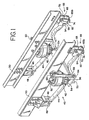
- FIG- 1 is an isometric view of the suspension system for a vehicle such as a light or heavy duty truck wherein the suspension system includes a novel shackle assembly of the present invention
- FIG. 2 is an elevational view of the suspension system illustrated in FIG. 1 ;
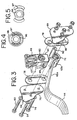
- FIG. 3 is an exploded isometric view of a shackle assembly constructed in accordance with the principles of the present invention and the distal end portion of its associated leaf spring;
- FIG. 4 is an elevational view of a bushing preferably used as a component of the shackle assembly.
- FIG. 5 is an elevational view of portions of the bushing illustrated in FIG.4 .
- FIGS. 1-2 illustrate a steering axle/front suspension system generally designated by reference number 40. It will be seen and understood that the construction of this suspension system on one side is duplicated on the opposite side of the vehicle. It will further be understood that, although the shackle assembly forming the subject matter of the present invention is shown as being positioned at the rear end of a leaf spring included with the suspension system, it could have equal utility at the opposite end of the leaf spring.
- the illustrated embodiment is directed to a combination air-mechanical suspension, it will be understood by those skilled in the art that the present invention has utility in strictly mechanical suspension as well. Still further, the present invention is not limited to single-leaf leaf spring suspensions, and is not limited to front suspensions, as illustrated.
- the active or functional components of the front suspension system 40 comprise two air springs 42-42 and two single-leaf leaf springs 44-44.
- Each single-leaf leaf spring 44 is provided with an eye 46 integrally formed at the proximal end thereof.
- Each eye 46 is pivotally connected to a standard or existing frame hanger indicated generally by reference numeral 48.
- the frame hangers 48 are mounted on each fore-and-aft extending chassis frame member 50.
- Each frame member 50 is constructed as a conventional C-shaped rail.
- An upper air spring support bracket 52 is mounted on each chassis frame member 50, and in the illustrative embodiment, is shown as being positioned at a location that is over one end of the vehicle front axle 53 and over the single-leaf leaf spring 44 on that side.
- the top portion of each air spring 42 is attached to its air spring support bracket 52.
- the underside of each air spring 42 is mounted on an air spring support pad 54 which, in the illustrative embodiment, is attached to the axle 53 extending from one side of front suspension system 40 to the other side.
- the single-leaf leaf spring 44 is positioned between the air spring support pad 54 and the axle 53.
- the single-leaf leaf spring is attached to the vehicle axle 53 in any known manner, such as by bolts 56-56, and it preferably assumes the form shown and described in U.S. Patent No. 5,938,221, issued August 17, 1999 , to which reference should be made. .
- a shock absorber 58 is also included within each side of front suspension system 40.
- the shock absorber 58 is pivotally connected at its upper end to a bracket 60 mounted on frame member 50 and is attached at its bottom end to axle 53 by a fitting 64.
- Shackle assembly 66 includes, preferably among other things, a shackle bracket 68 fixedly mounted to vehicle frame 50 and depending inner and outer shackle plates 69, 70.
- an elastomer (e.g., rubber) bushing 72 with voids oriented such that the voids are vertically spaced with respect to each other is shown installed within the leaf spring eye 65b and between shackle plates 69, 70 by fastener 74.
- Bushing 72 preferably has a bowtie-shape configuration.
- Fastener 74 is inserted through and connects shackle plate 70, wear pad 76, bushing 72 installed in leaf spring eye 65b, wear pad 78 and shackle plate 69.
- a second elastomer bushing 80 with voids oriented such that the voids are vertically spaced with respect to each other is shown to be installed within the shackle bracket 68 and between shackle plates 69, 70 and wear pads 76, 78 by fastener 82.
- Bushing 80 also preferably has a bowtie-shape configuration.
- Fastener 82 is inserted through and connects shackle plate 70, wear pad 76, bushing 80 (installed into a bore positioned within shackle bracket 68), wear pad 78 and shackle plate 69.
- the functional aspects of elastomer bushings 72, 80 will be discussed in greater detail with respect to FIGS. 4-5 .
- Shackle plates 69, 70 include upwardly extending fingers 84, 86 forming portions of the shackle plates and positioned on one side thereof.
- FIG. 3 shows fingers 84, 86 positioned on the preferred axle sides of shackle plates 69, 70.
- Each finger 84, 86 provides a novel redundancy feature, wherein the fingers 84, 86 will contact the bottom of frame rail 50 during certain conditions when the opposite limb of the same side leaf spring is broken.
- the shackle plate fingers 84, 86 will contact the bottom of frame member 50 and prevent the axle 53 from excessive longitudinal movement relative to the chassis when the vehicle is moving in a first general direction and is subjected to deceleration. (e.g., braking).
- shackle assembly 66 connects the rear end of a leaf spring to frame 50 and shackle plate fingers 84, 86 are positioned on the axle sides of shackle plates 69, 70, in the event that the front limb of the leaf spring positioned on the same vehicle side breaks, and in the event the vehicle is in reverse, traveling in a generally rearward direction and is subject to deceleration, shackle plates 69, 70 will pivot at fastener 82 until fingers 84, 86 contact against the bottom of frame rail 50.
- the shackle assembly connects the rear end of the leaf spring to the frame rail, and is oriented such that the shackle plate fingers are positioned on the axle side of the shackle plate, and in the event that there is front limb failure on the driver's side (drag link side), drag link forces to steer the vehicle to the left (for typical right-hand drive vehicles used in North America) will cause the axle to the roll forward on that side. Under such circumstances, the shackle plate fingers 84, 86 will contact the bottom of frame rail 50 to prevent any further motion beyond the stopping point (i.e., the point where contact is made).
- shackle assembly 66 connects the front end of a leaf spring to frame 50, and the shackle plates are oriented such that shackle plate fingers 84, 86 are positioned on the sides of the shackle plates closest to the vehicle axle, in the event that the rear limb of the leaf spring positioned on the same vehicle side breaks, and in the event that the vehicle is in drive, travelling in a generally forward direction and is subject to deceleration, the shackle plates will pivot at the fastener that pivotally connects the plates to the shackle bracket until the fingers, which extend upward and, in this case, towards the axle, contact the bottom of the vehicle frame rail.
- the shackle assembly connects the front end of the leaf spring to the frame rail and is oriented such that the shackle plate fingers are positioned on the axle side of the shackle plate, and in the event that there is rear limb failure on the driver's side, and the vehicle is turned to the right, it will cause the axle to roll backward on that side. Under such circumstances, the shackle plate fingers 84, 86 will contact the bottom of frame rail 50 to prevent any further motion beyond the stopping point (i.e., the point where contact is made).
- axle movement allows for greater steering control of the vehicle.
- shackle plates can also be oriented such that the shackle plate fingers are positioned on the sides of the shackle plates furthest from the vehicle axle, but this orientation would present design issues and would operate in a correspondingly different fashion. Other variables would affect operation as well.
- the shackle bracket 68 includes legs 88, 90, which provide a wear surface and load reaction point for the shackle wear pads 76, 78, and, in turn, a load reaction point for shackle plates 69, 70.
- legs 88, 90 which provide a wear surface and load reaction point for the shackle wear pads 76, 78, and, in turn, a load reaction point for shackle plates 69, 70.
- side loads are reacted through the legs 88; 90, wear pads 76, 78, and shackle plates 69, 70, thereby providing a system that is both laterally and conically stiff (as defined about the longitudinal axis).
- the bushing 72 is not required to react to side loads through conical loading, thereby allowing the bushing to be more versatile in accommodating other loads as will be discussed in greater detail with respect to FIGS. 4-5 .
- wear pads 76, 78 further alleviate stress to shackle plates 69, 70, leaf spring eye 65b,
- Legs 88, 90 of shackle bracket 68 further provide a reaction point for a laterally extending shackle stop 92 shown in the form of a tube.
- Shackle stop 92 is secured between shackle plates 69, 70 by fastener 94, and is positioned at the same side of the shackle plates at the shackle plate fingers 84, 86.
- the shackle stop 92 is positioned in the side of shackle plates 69, 70 closest to the vehicle axle.
- Shackle stop 92 also serves as a redundancy feature, thereby providing longitudinal control of the axle in the event that the opposite limb of the same vehicle side leaf spring 44 is broken.
- the shackle assembly connects the rear end of the leaf spring to the frame rail and is oriented such that the shackle stop is positioned on the axle side of the shackle plate, and in the event that there is front limb failure on the driver's side and the vehicle is turned to the right (for typical right-hand drive vehicles used in North America), the axle will be caused to roll backward on that side. Under such circumstances, the shackle stop 92 will contact the legs 88, 90 of the shackle bracket 68 to prevent any further motion beyond the stopping point (i.e., the point where contact is made).
- shackle assembly 66 connects the front end of a leaf spring to frame 50 and is oriented such that the shackle stop is positioned on the axle sides of the shackle plates, in the event that the rear limb of the leaf spring breaks, and in the event that the vehicle is in reverse, travelling in a generally rearward direction and is subject to deceleration, the shackle plates will pivot at the fastener that pivotally connects the plates to the shackle bracket the snackle stop 92 contacts the legs 88, 90 of the shackle bracket 68. Further movement is thereby prevented.
- the shackle assembly connects the front end of the leaf spring to the frame rail and is oriented such that the shackle stop is positioned on the axle side of the shackle plate, and in the event that there is rear limb failure on the driver's side (drag link side), drag link forces to steer the vehicle to the left (for typical right-hand drive vehicles used in North America) will cause to the axle to roll forward on that side. Under such circumstances, the shackle stop 92 will contact legs 88, 90 of the shackle bracket 68 to prevent any further motion beyond the stopping point (i.e., the point where contact is made).
- axle movement allows for greater steering control of the vehicle.
- shackle plates can also be oriented such that the shackle plate fingers are positioned on the sides of the shackle plates furthest from the vehicle axle, but this orientation would present design issues and would operate in a ' correspondingly different fashion. Other variables would affect operation as well.
- bushings 72, 80 can be installed within shackle bracket 68 and leaf spring eye 65b, respectively, and still achieve adequate performance.
- bushings 72, 80 include an inner metal sleeve 96, an elastomer layer 97 enveloping the inner metal sleeve and an outer metal sleeve 98.
- the elastomer layer 97 has a bowtie-shaped configuration and two vertically spaced voids are positioned between the elastomer layer and outer metal sleeve 98 at generally upper and lower sides of the bushing.
- the voids present within the bushings 72, 80 allow for increased vertical compliance, thereby providing additional vertical travel for suspension. More specifically, this additional vertical suspension travel helps to reduce the potential of spring damage due to reverse loading, while, at the same time, providing for better ride quality.
- this vertical compliance is particularly desirable where the length of the spring is restricted and where it is difficult to achieve desired axle travel due to stress limitations in the spring material. In hybrid air-spring suspensions, such as the suspension illustrated in Figs. 1 and 2 , this is further desirable in situations where the air spring has a tendency to push the spring into reversal during rebound conditions, including axle overhang.
- the elastomer layer 97 enveloping the inner metal sleeve 96 of the bowtie bushings 72, 80 allows for increased torsional compliance (defined about the lateral axis), More specifically, this configuration significantly decreases auxiliary stiffening of the suspension vertical rate due to winding up of the torsional stiffness of the bushings. Additionally, the elastomer 97 tolerates large torsion angles, thereby allowing increased spring deflection.
- elastomer layer 97 enveloping the inner metal sleeve of bushings 72, 80 is conically compliant (defined about a longitudinal axis).
Landscapes
- Engineering & Computer Science (AREA)
- Mechanical Engineering (AREA)
- General Engineering & Computer Science (AREA)
- Vehicle Body Suspensions (AREA)
- Load-Engaging Elements For Cranes (AREA)
- Control And Other Processes For Unpacking Of Materials (AREA)
- Mechanical Coupling Of Light Guides (AREA)
- Vibration Prevention Devices (AREA)
- Braking Arrangements (AREA)
- Hooks, Suction Cups, And Attachment By Adhesive Means (AREA)
Priority Applications (1)
| Application Number | Priority Date | Filing Date | Title |
|---|---|---|---|
| EP07023214A EP1987969B1 (en) | 2002-10-24 | 2003-10-21 | Shackle assembly |
Applications Claiming Priority (3)
| Application Number | Priority Date | Filing Date | Title |
|---|---|---|---|
| US280120 | 2002-10-24 | ||
| US10/280,120 US20040080135A1 (en) | 2002-10-24 | 2002-10-24 | Shackle assembly |
| PCT/US2003/033390 WO2004037570A1 (en) | 2002-10-24 | 2003-10-21 | Shackle assembly |
Related Child Applications (1)
| Application Number | Title | Priority Date | Filing Date |
|---|---|---|---|
| EP07023214A Division EP1987969B1 (en) | 2002-10-24 | 2003-10-21 | Shackle assembly |
Publications (3)
| Publication Number | Publication Date |
|---|---|
| EP1583672A1 EP1583672A1 (en) | 2005-10-12 |
| EP1583672A4 EP1583672A4 (en) | 2006-05-10 |
| EP1583672B1 true EP1583672B1 (en) | 2009-08-05 |
Family
ID=32106844
Family Applications (2)
| Application Number | Title | Priority Date | Filing Date |
|---|---|---|---|
| EP03779153A Expired - Lifetime EP1583672B1 (en) | 2002-10-24 | 2003-10-21 | Shackle assembly |
| EP07023214A Expired - Lifetime EP1987969B1 (en) | 2002-10-24 | 2003-10-21 | Shackle assembly |
Family Applications After (1)
| Application Number | Title | Priority Date | Filing Date |
|---|---|---|---|
| EP07023214A Expired - Lifetime EP1987969B1 (en) | 2002-10-24 | 2003-10-21 | Shackle assembly |
Country Status (13)
| Country | Link |
|---|---|
| US (2) | US20040080135A1 (enExample) |
| EP (2) | EP1583672B1 (enExample) |
| JP (2) | JP2006503750A (enExample) |
| KR (1) | KR20050074499A (enExample) |
| CN (1) | CN100480075C (enExample) |
| AT (2) | ATE554955T1 (enExample) |
| AU (1) | AU2003285922B2 (enExample) |
| BR (1) | BR0315658B1 (enExample) |
| CA (2) | CA2706871C (enExample) |
| DE (1) | DE60328716D1 (enExample) |
| MX (1) | MXPA05004289A (enExample) |
| NZ (2) | NZ539740A (enExample) |
| WO (1) | WO2004037570A1 (enExample) |
Families Citing this family (63)
| Publication number | Priority date | Publication date | Assignee | Title |
|---|---|---|---|---|
| US8029008B2 (en) * | 2005-04-27 | 2011-10-04 | Hendrickson Usa, L.L.C. | Vehicle suspensions having leaf springs and alternative clamp groups |
| US20060244236A1 (en) | 2005-04-27 | 2006-11-02 | Cortez Jerome L | Vehicle suspensions having leaf springs and alternative clamp groups |
| US7360778B2 (en) * | 2005-10-13 | 2008-04-22 | Smith Kim H | Traction device |
| US7484745B2 (en) * | 2006-03-07 | 2009-02-03 | Gm Global Technology Operations, Inc. | Brinelling bushing joint assembly |
| DE202006016061U1 (de) * | 2006-10-13 | 2006-12-21 | Goldschmitt Techmobil Gmbh | Achsaufhängung mit zwei Radführungsfedern |
| US7690660B2 (en) * | 2007-03-29 | 2010-04-06 | Hendrickson Usa, L.L.C. | Leading and trailing arm suspensions having a fully integrated arm |
| DE102007016741B4 (de) * | 2007-04-07 | 2015-01-08 | Hübner GmbH | Elastomer-Metall-Element für ein Elastomer-Metall-Lager, insbesondere als Lagerverbindung zwischen einem Kuppelmodul und einem Fahrzeug |
| US7673891B2 (en) * | 2007-08-07 | 2010-03-09 | Lippert Components Inc. | Suspension system shackle link with shock absorber |
| EP2181004A1 (en) * | 2007-09-01 | 2010-05-05 | Robert Gerrard | Leaf spring suspension system |
| CA2645438C (en) * | 2008-02-06 | 2016-03-29 | Simard Suspensions Inc. | Tandem suspension for a vehicle |
| DE102008008006A1 (de) * | 2008-02-07 | 2009-04-09 | Daimler Ag | Achsführung eines Fahrzeugs |
| US7926836B2 (en) | 2008-03-10 | 2011-04-19 | Hendrickson Usa, Llc. | Elastomeric spring vehicle suspension |
| USD606459S1 (en) | 2008-03-10 | 2009-12-22 | Hendrickson Usa, L.L.C. | Suspension saddle |
| US8052166B2 (en) | 2008-03-10 | 2011-11-08 | Hendrickson Usa, Llc. | Tie-plate and frame hanger of a suspension assembly |
| USD603303S1 (en) | 2008-03-10 | 2009-11-03 | Hendrickson Usa, L.L.C. | Suspension spring |
| USD610952S1 (en) | 2008-03-10 | 2010-03-02 | Hendrickson Usa, L.L.C. | Suspension assembly |
| US8152195B2 (en) * | 2008-03-10 | 2012-04-10 | Hendrickson Usa, Llc | Modular suspension system and components thereof |
| US8302988B2 (en) | 2008-03-10 | 2012-11-06 | Hendrickson Usa, L.L.C. | Suspension assembly with tie-plate |
| USD622642S1 (en) | 2008-03-10 | 2010-08-31 | Hendrickson Usa, L.L.C. | Saddle for a suspension |
| USD605984S1 (en) | 2008-03-10 | 2009-12-15 | Hendrickson Usa, L.L.C. | Shear spring for a suspension |
| USD615005S1 (en) | 2008-03-10 | 2010-05-04 | Hendrickson Usa, L.L.C. | Spring housing for a suspension |
| CN101875288B (zh) * | 2009-04-30 | 2013-12-11 | 陕西欧舒特汽车股份有限公司 | 一种安全可靠的客车前空气悬架导向板保护装置的设计方法 |
| USD630137S1 (en) | 2009-06-02 | 2011-01-04 | Hendrickson Usa, L.L.C. | Progressive rate spring for a suspension |
| USD624461S1 (en) | 2009-06-02 | 2010-09-28 | Hendrickson Usa, L.L.C. | Spring mount for a suspension |
| USD624462S1 (en) | 2009-06-02 | 2010-09-28 | Hendrickson Usa, L.L.C. | Spring housing for a suspension |
| USD633011S1 (en) | 2009-06-02 | 2011-02-22 | Hendrickson Usa, L.L.C. | Suspension assembly |
| USD645794S1 (en) | 2009-08-22 | 2011-09-27 | Hendrickson Usa, L.L.C. | Suspension tie-plate |
| CN101863209A (zh) * | 2010-06-18 | 2010-10-20 | 力帆实业(集团)股份有限公司 | 一种吊耳结构 |
| CN101863208A (zh) * | 2010-06-18 | 2010-10-20 | 力帆实业(集团)股份有限公司 | 三轮车吊耳组合 |
| JP5620755B2 (ja) * | 2010-08-31 | 2014-11-05 | 日野自動車株式会社 | サスペンション装置 |
| USD672286S1 (en) | 2010-09-05 | 2012-12-11 | Hendrickson Usa, L.L.C. | Suspension assembly |
| USD672287S1 (en) | 2010-09-05 | 2012-12-11 | Hendrickson Usa, L.L.C. | Frame-hanger-to-frame-hanger tie-plate |
| USD649917S1 (en) | 2010-09-05 | 2011-12-06 | Hendrickson Usa, L.L.C. | Spring housing for a suspension |
| USD648249S1 (en) | 2010-09-05 | 2011-11-08 | Hendrickson Usa, L.L.C. | Saddle for a suspension |
| CN101947906A (zh) * | 2010-09-20 | 2011-01-19 | 包头市瑜利物流有限公司 | 整体插接式挂车悬架装置 |
| US9004512B2 (en) | 2011-07-08 | 2015-04-14 | Hendrickson Usa, L.L.C. | Shear spring useful for vehicle suspension |
| US8262112B1 (en) | 2011-07-08 | 2012-09-11 | Hendrickson Usa, L.L.C. | Vehicle suspension and improved method of assembly |
| CA2901215C (en) | 2011-07-08 | 2016-09-13 | Hendrickson Usa, L.L.C. | Vehicle suspension and improved method of assembly |
| CN102489950B (zh) * | 2011-12-01 | 2013-11-06 | 中国重汽集团济南动力有限公司 | 汽车前悬组合支架总成的加工工艺 |
| MX347894B (es) * | 2011-12-22 | 2017-05-18 | Volvo Lastvagnar Ab | Muelle de lámina flexible frontal. |
| USD700113S1 (en) | 2012-07-06 | 2014-02-25 | Hendrickson Usa, L.L.C. | Suspension assembly |
| USD699637S1 (en) | 2012-07-06 | 2014-02-18 | Hendrickson Usa, L.L.C. | Shear spring for a suspension |
| USD700112S1 (en) | 2012-07-06 | 2014-02-25 | Hendrickson Usa, L.L.C. | Progressive rate spring for a suspension |
| US9085212B2 (en) | 2013-03-15 | 2015-07-21 | Hendrickson Usa, L.L.C. | Vehicle suspension |
| GB2514536B (en) * | 2013-03-18 | 2017-05-03 | Alexander Dennis Ltd | Suspension arrangement |
| US9150071B2 (en) | 2013-07-25 | 2015-10-06 | Hendrickson Usa, L.L.C. | Frame hanger for vehicle suspension |
| US9073401B2 (en) * | 2013-09-24 | 2015-07-07 | Ford Global Technologies, Llc | Vehicle suspension mounting system |
| US9937904B1 (en) * | 2015-10-02 | 2018-04-10 | Iscar Gse Corp. | Brake unit for a cargo dolly |
| WO2017075427A1 (en) | 2015-10-29 | 2017-05-04 | Hendrickson Usa, L.L.C. | Shackle assembly |
| CN109070673B (zh) * | 2015-11-30 | 2022-11-01 | 亨德里克森美国有限责任公司 | 悬架组件 |
| GB2545229B (en) * | 2015-12-09 | 2018-12-05 | Ifor Williams Trailers Ltd | Vehicle suspension system |
| US10286743B2 (en) * | 2016-09-13 | 2019-05-14 | Continental Automotive Systems, Inc. | Vehicle axle suspension arrangement |
| RU171719U1 (ru) * | 2016-10-03 | 2017-06-13 | Публичное акционерное общество "КАМАЗ" | Пружинная подвеска транспортного средства |
| US11090995B2 (en) * | 2017-05-15 | 2021-08-17 | Volvo Truck Corporation | Suspension system of a vehicle axle |
| DE102018201435B4 (de) | 2018-01-31 | 2021-11-11 | Ford Global Technologies, Llc | Achsaufhängung |
| AT520864B1 (de) * | 2018-02-14 | 2023-04-15 | Hendrickson Comm Vehicle Sys Europe Gmbh | Feder zur Verwendung im Zusammenhang mit einem Fahrzeug |
| RU183693U1 (ru) * | 2018-05-29 | 2018-10-01 | Публичное акционерное общество "КАМАЗ" | Зависимая рессорная подвеска транспортного средства |
| RU183896U1 (ru) * | 2018-05-29 | 2018-10-08 | Публичное акционерное общество "КАМАЗ" | Устройство стабилизации поперечной устойчивости транспортного средства |
| US11167614B2 (en) * | 2019-02-19 | 2021-11-09 | Rassini Suspensiones, S.A. De C.V. | Progressive rate leaf spring for vehicle suspension system |
| RU195944U1 (ru) * | 2019-09-25 | 2020-02-11 | Публичное акционерное общество "КАМАЗ" | Узел крепления элементов подвески транспортного средства |
| DE102020115740A1 (de) * | 2020-06-15 | 2021-12-16 | Rheinmetall MAN Military Vehicles Österreich GesmbH | Militärisches Nutzfahrzeug |
| RU200215U1 (ru) * | 2020-06-25 | 2020-10-13 | Публичное акционерное общество "КАМАЗ" | Передняя подвеска транспортного средства |
| EP4261056B1 (en) * | 2022-04-12 | 2025-06-11 | Volvo Truck Corporation | A leaf spring arrangement for use in a vehicle suspension |
Family Cites Families (31)
| Publication number | Priority date | Publication date | Assignee | Title |
|---|---|---|---|---|
| DE378963C (de) | 1923-08-10 | Moll Werke Akt Ges | Vorderfederaufhaengung fuer Kraftfahrzeuge | |
| US1350110A (en) * | 1920-08-17 | Combined shock-absorbeb | ||
| US1190966A (en) * | 1915-11-30 | 1916-07-11 | Frank N Sprague | Shackle for the springs of automobiles and other vehicles. |
| US1427144A (en) * | 1921-02-01 | 1922-08-29 | W B Lindsay | Vehicle spring and clip therefor |
| US1487427A (en) * | 1922-02-09 | 1924-03-18 | Dorsey F Asbury | Spring shackle |
| DE409826C (de) | 1923-05-03 | 1925-02-16 | Jean Visart | Vorderfederaufhaengung fuer Kraftfahrzeuge |
| FR569371A (fr) * | 1923-08-14 | 1924-04-11 | Perfectionnements au montage des ressorts de véhicules | |
| US2004712A (en) * | 1930-06-02 | 1935-06-11 | Thiry Leon | Elastic shaft coupling |
| US2048256A (en) * | 1933-09-15 | 1936-07-21 | Gen Motors Corp | Oscillating pivot joint unit |
| US2297483A (en) * | 1939-12-28 | 1942-09-29 | Kuhne Kurt Karl | Elastic connecting link |
| US2802663A (en) * | 1956-04-05 | 1957-08-13 | Albert H Hovind | Spring suspension |
| US3030101A (en) * | 1959-02-12 | 1962-04-17 | Lester A Mcintosh | Spring shackle |
| US3508745A (en) * | 1967-07-13 | 1970-04-28 | Gen Tire & Rubber Co | Elastomeric closed end triple-rate bushing |
| GB1202482A (en) * | 1968-01-16 | 1970-08-19 | Ford Motor Co | Motor vehicle leaf spring assembly |
| FR2335744A1 (fr) * | 1975-12-15 | 1977-07-15 | Citroen Sa | Assemblage elastique a rigidite differentielle |
| JPS5471322U (enExample) * | 1977-10-28 | 1979-05-21 | ||
| JPS5849843Y2 (ja) * | 1979-10-16 | 1983-11-14 | マツダ株式会社 | シヤックル構造 |
| US4412690A (en) * | 1981-04-22 | 1983-11-01 | Kelsey-Hayes Co. | Suspension system |
| JPS5960009A (ja) * | 1982-09-29 | 1984-04-05 | Toshiba Corp | 軸流タ−ボ機械 |
| JPS62144708U (enExample) * | 1986-03-07 | 1987-09-12 | ||
| US4718693A (en) * | 1986-06-11 | 1988-01-12 | Booher Benjamin V | Composite leaf spring suspension with integral sway bar |
| AU8033987A (en) * | 1986-10-04 | 1988-04-21 | Gkn Technology Limited | Vehicle suspension |
| GB2211473B (en) * | 1987-10-28 | 1991-09-04 | Vauxhall Motors Ltd | Vehicle rear suspension |
| US4872653A (en) * | 1988-04-11 | 1989-10-10 | Chuchua Brian N | Shackle for use in limiting the movement of an end of a leaf spring in a wheeled vehicle |
| JP2705132B2 (ja) * | 1988-08-23 | 1998-01-26 | 日本電気株式会社 | 配線形成方法および装置 |
| JPH0256932U (enExample) * | 1988-10-19 | 1990-04-24 | ||
| JPH02136703U (enExample) * | 1989-04-19 | 1990-11-14 | ||
| AUPN032694A0 (en) * | 1994-12-23 | 1995-01-27 | Thanksmate Pty Ltd | Improved vehicle |
| US5813698A (en) * | 1996-10-02 | 1998-09-29 | Illinois Tool Works Inc. | Payload dependent stabilizer system |
| US5938221A (en) * | 1997-12-08 | 1999-08-17 | The Boler Company | Tapered convolute leaf spring for truck suspensions |
| US6129369A (en) * | 1998-03-18 | 2000-10-10 | The Boler Company. | Leaf spring distal end portion single rotation point attachment part |
-
2002
- 2002-10-24 US US10/280,120 patent/US20040080135A1/en not_active Abandoned
-
2003
- 2003-10-21 CN CNB2003801056822A patent/CN100480075C/zh not_active Expired - Fee Related
- 2003-10-21 JP JP2004546986A patent/JP2006503750A/ja active Pending
- 2003-10-21 CA CA2706871A patent/CA2706871C/en not_active Expired - Fee Related
- 2003-10-21 NZ NZ539740A patent/NZ539740A/en unknown
- 2003-10-21 AU AU2003285922A patent/AU2003285922B2/en not_active Ceased
- 2003-10-21 AT AT07023214T patent/ATE554955T1/de active
- 2003-10-21 WO PCT/US2003/033390 patent/WO2004037570A1/en not_active Ceased
- 2003-10-21 EP EP03779153A patent/EP1583672B1/en not_active Expired - Lifetime
- 2003-10-21 EP EP07023214A patent/EP1987969B1/en not_active Expired - Lifetime
- 2003-10-21 NZ NZ570934A patent/NZ570934A/en unknown
- 2003-10-21 MX MXPA05004289A patent/MXPA05004289A/es active IP Right Grant
- 2003-10-21 CA CA2503522A patent/CA2503522C/en not_active Expired - Fee Related
- 2003-10-21 DE DE60328716T patent/DE60328716D1/de not_active Expired - Lifetime
- 2003-10-21 BR BRPI0315658-3A patent/BR0315658B1/pt not_active IP Right Cessation
- 2003-10-21 KR KR1020057007120A patent/KR20050074499A/ko not_active Ceased
- 2003-10-21 AT AT03779153T patent/ATE438527T1/de not_active IP Right Cessation
-
2004
- 2004-08-10 US US10/914,978 patent/US7229088B2/en not_active Expired - Lifetime
-
2010
- 2010-04-05 JP JP2010086895A patent/JP2010173642A/ja active Pending
Also Published As
| Publication number | Publication date |
|---|---|
| EP1583672A4 (en) | 2006-05-10 |
| BR0315658B1 (pt) | 2012-12-25 |
| EP1987969A2 (en) | 2008-11-05 |
| NZ539740A (en) | 2008-10-31 |
| EP1987969A3 (en) | 2009-01-21 |
| US7229088B2 (en) | 2007-06-12 |
| KR20050074499A (ko) | 2005-07-18 |
| DE60328716D1 (de) | 2009-09-17 |
| CA2706871C (en) | 2013-02-19 |
| ATE438527T1 (de) | 2009-08-15 |
| CA2503522C (en) | 2010-08-31 |
| CN100480075C (zh) | 2009-04-22 |
| MXPA05004289A (es) | 2005-10-18 |
| US20050189734A1 (en) | 2005-09-01 |
| US20040080135A1 (en) | 2004-04-29 |
| JP2010173642A (ja) | 2010-08-12 |
| CA2706871A1 (en) | 2004-05-06 |
| ATE554955T1 (de) | 2012-05-15 |
| EP1583672A1 (en) | 2005-10-12 |
| AU2003285922B2 (en) | 2009-08-06 |
| CA2503522A1 (en) | 2004-05-06 |
| CN1738726A (zh) | 2006-02-22 |
| JP2006503750A (ja) | 2006-02-02 |
| BR0315658A (pt) | 2005-08-30 |
| AU2003285922A1 (en) | 2004-05-13 |
| EP1987969B1 (en) | 2012-04-25 |
| NZ570934A (en) | 2008-11-28 |
| WO2004037570A1 (en) | 2004-05-06 |
Similar Documents
| Publication | Publication Date | Title |
|---|---|---|
| EP1583672B1 (en) | Shackle assembly | |
| EP1693592B1 (en) | Blattfedereinrichtung mit ganzem Blatt-Blattfederbauelement und halbem Blatt-Blattfederbauelement | |
| US8177246B2 (en) | Axle seat for vehicle suspensions | |
| US6485040B1 (en) | Single rotation point attachment part for leaf springs | |
| EP1648722B1 (en) | Frame integrated rear suspension | |
| US4779893A (en) | Strut type vehicle wheel suspension | |
| US20060103103A1 (en) | Lightweight, low part-count, suspension system for wheeled vehicles | |
| US7520515B2 (en) | Steer axle suspension | |
| CA2208969C (en) | Direct pull dual compensating stabilizer system | |
| EP1120299B1 (en) | Mounting structure for suspension V-Rod | |
| GB2272407A (en) | A vehicle suspension torque arm assembly | |
| US6739608B2 (en) | Suspension system for a vehicle | |
| US7249780B1 (en) | Air assist adaptation for leaf spring suspension systems | |
| US4632422A (en) | Anti-roll torsion bar (stabilizer) for the running gear of vehicles | |
| US12472787B2 (en) | Load equalizer assembly for tandem steer suspension | |
| US10894455B2 (en) | Trailing-arm suspension with leaf springs | |
| EP0045411A2 (en) | Equalized four-spring tandem axle suspension | |
| KR102113081B1 (ko) | 바퀴를 차량의 차체에 연결하기 위한 차축 장치 | |
| WO2019045700A1 (en) | MECHANICAL STOP FOR AXLE / SUSPENSION SYSTEMS | |
| JPS63502498A (ja) | 車輌用サスペンション |
Legal Events
| Date | Code | Title | Description |
|---|---|---|---|
| PUAI | Public reference made under article 153(3) epc to a published international application that has entered the european phase |
Free format text: ORIGINAL CODE: 0009012 |
|
| 17P | Request for examination filed |
Effective date: 20050520 |
|
| AK | Designated contracting states |
Kind code of ref document: A1 Designated state(s): AT BE BG CH CY CZ DE DK EE ES FI FR GB GR HU IE IT LI LU MC NL PT RO SE SI SK TR |
|
| AX | Request for extension of the european patent |
Extension state: AL LT LV MK |
|
| DAX | Request for extension of the european patent (deleted) | ||
| A4 | Supplementary search report drawn up and despatched |
Effective date: 20060324 |
|
| RIC1 | Information provided on ipc code assigned before grant |
Ipc: B60G 11/10 20060101ALI20060320BHEP Ipc: B60G 7/04 20060101ALI20060320BHEP Ipc: B60G 11/04 20060101AFI20040511BHEP Ipc: B60G 11/46 20060101ALI20060320BHEP |
|
| 17Q | First examination report despatched |
Effective date: 20061212 |
|
| GRAP | Despatch of communication of intention to grant a patent |
Free format text: ORIGINAL CODE: EPIDOSNIGR1 |
|
| GRAS | Grant fee paid |
Free format text: ORIGINAL CODE: EPIDOSNIGR3 |
|
| GRAA | (expected) grant |
Free format text: ORIGINAL CODE: 0009210 |
|
| AK | Designated contracting states |
Kind code of ref document: B1 Designated state(s): AT BE BG CH CY CZ DE DK EE ES FI FR GB GR HU IE IT LI LU MC NL PT RO SE SI SK TR |
|
| REG | Reference to a national code |
Ref country code: GB Ref legal event code: FG4D |
|
| REG | Reference to a national code |
Ref country code: CH Ref legal event code: EP |
|
| REG | Reference to a national code |
Ref country code: IE Ref legal event code: FG4D |
|
| REF | Corresponds to: |
Ref document number: 60328716 Country of ref document: DE Date of ref document: 20090917 Kind code of ref document: P |
|
| REG | Reference to a national code |
Ref country code: SE Ref legal event code: TRGR |
|
| PG25 | Lapsed in a contracting state [announced via postgrant information from national office to epo] |
Ref country code: AT Free format text: LAPSE BECAUSE OF FAILURE TO SUBMIT A TRANSLATION OF THE DESCRIPTION OR TO PAY THE FEE WITHIN THE PRESCRIBED TIME-LIMIT Effective date: 20090805 Ref country code: FI Free format text: LAPSE BECAUSE OF FAILURE TO SUBMIT A TRANSLATION OF THE DESCRIPTION OR TO PAY THE FEE WITHIN THE PRESCRIBED TIME-LIMIT Effective date: 20090805 Ref country code: ES Free format text: LAPSE BECAUSE OF FAILURE TO SUBMIT A TRANSLATION OF THE DESCRIPTION OR TO PAY THE FEE WITHIN THE PRESCRIBED TIME-LIMIT Effective date: 20091116 |
|
| PG25 | Lapsed in a contracting state [announced via postgrant information from national office to epo] |
Ref country code: SI Free format text: LAPSE BECAUSE OF FAILURE TO SUBMIT A TRANSLATION OF THE DESCRIPTION OR TO PAY THE FEE WITHIN THE PRESCRIBED TIME-LIMIT Effective date: 20090805 |
|
| PG25 | Lapsed in a contracting state [announced via postgrant information from national office to epo] |
Ref country code: BG Free format text: LAPSE BECAUSE OF FAILURE TO SUBMIT A TRANSLATION OF THE DESCRIPTION OR TO PAY THE FEE WITHIN THE PRESCRIBED TIME-LIMIT Effective date: 20091105 Ref country code: PT Free format text: LAPSE BECAUSE OF FAILURE TO SUBMIT A TRANSLATION OF THE DESCRIPTION OR TO PAY THE FEE WITHIN THE PRESCRIBED TIME-LIMIT Effective date: 20091205 |
|
| PG25 | Lapsed in a contracting state [announced via postgrant information from national office to epo] |
Ref country code: EE Free format text: LAPSE BECAUSE OF FAILURE TO SUBMIT A TRANSLATION OF THE DESCRIPTION OR TO PAY THE FEE WITHIN THE PRESCRIBED TIME-LIMIT Effective date: 20090805 Ref country code: CZ Free format text: LAPSE BECAUSE OF FAILURE TO SUBMIT A TRANSLATION OF THE DESCRIPTION OR TO PAY THE FEE WITHIN THE PRESCRIBED TIME-LIMIT Effective date: 20090805 Ref country code: DK Free format text: LAPSE BECAUSE OF FAILURE TO SUBMIT A TRANSLATION OF THE DESCRIPTION OR TO PAY THE FEE WITHIN THE PRESCRIBED TIME-LIMIT Effective date: 20090805 Ref country code: RO Free format text: LAPSE BECAUSE OF FAILURE TO SUBMIT A TRANSLATION OF THE DESCRIPTION OR TO PAY THE FEE WITHIN THE PRESCRIBED TIME-LIMIT Effective date: 20090805 |
|
| PG25 | Lapsed in a contracting state [announced via postgrant information from national office to epo] |
Ref country code: MC Free format text: LAPSE BECAUSE OF NON-PAYMENT OF DUE FEES Effective date: 20091031 Ref country code: SK Free format text: LAPSE BECAUSE OF FAILURE TO SUBMIT A TRANSLATION OF THE DESCRIPTION OR TO PAY THE FEE WITHIN THE PRESCRIBED TIME-LIMIT Effective date: 20090805 |
|
| REG | Reference to a national code |
Ref country code: CH Ref legal event code: PL |
|
| PLBE | No opposition filed within time limit |
Free format text: ORIGINAL CODE: 0009261 |
|
| STAA | Information on the status of an ep patent application or granted ep patent |
Free format text: STATUS: NO OPPOSITION FILED WITHIN TIME LIMIT |
|
| 26N | No opposition filed |
Effective date: 20100507 |
|
| PG25 | Lapsed in a contracting state [announced via postgrant information from national office to epo] |
Ref country code: LI Free format text: LAPSE BECAUSE OF NON-PAYMENT OF DUE FEES Effective date: 20091031 Ref country code: CH Free format text: LAPSE BECAUSE OF NON-PAYMENT OF DUE FEES Effective date: 20091031 Ref country code: GR Free format text: LAPSE BECAUSE OF FAILURE TO SUBMIT A TRANSLATION OF THE DESCRIPTION OR TO PAY THE FEE WITHIN THE PRESCRIBED TIME-LIMIT Effective date: 20091106 Ref country code: IE Free format text: LAPSE BECAUSE OF NON-PAYMENT OF DUE FEES Effective date: 20091021 |
|
| PG25 | Lapsed in a contracting state [announced via postgrant information from national office to epo] |
Ref country code: LU Free format text: LAPSE BECAUSE OF NON-PAYMENT OF DUE FEES Effective date: 20091021 |
|
| PG25 | Lapsed in a contracting state [announced via postgrant information from national office to epo] |
Ref country code: HU Free format text: LAPSE BECAUSE OF FAILURE TO SUBMIT A TRANSLATION OF THE DESCRIPTION OR TO PAY THE FEE WITHIN THE PRESCRIBED TIME-LIMIT Effective date: 20100206 |
|
| PG25 | Lapsed in a contracting state [announced via postgrant information from national office to epo] |
Ref country code: TR Free format text: LAPSE BECAUSE OF FAILURE TO SUBMIT A TRANSLATION OF THE DESCRIPTION OR TO PAY THE FEE WITHIN THE PRESCRIBED TIME-LIMIT Effective date: 20090805 |
|
| PG25 | Lapsed in a contracting state [announced via postgrant information from national office to epo] |
Ref country code: CY Free format text: LAPSE BECAUSE OF FAILURE TO SUBMIT A TRANSLATION OF THE DESCRIPTION OR TO PAY THE FEE WITHIN THE PRESCRIBED TIME-LIMIT Effective date: 20090805 |
|
| REG | Reference to a national code |
Ref country code: FR Ref legal event code: PLFP Year of fee payment: 13 |
|
| PGFP | Annual fee paid to national office [announced via postgrant information from national office to epo] |
Ref country code: BE Payment date: 20151027 Year of fee payment: 13 |
|
| REG | Reference to a national code |
Ref country code: FR Ref legal event code: PLFP Year of fee payment: 14 |
|
| PG25 | Lapsed in a contracting state [announced via postgrant information from national office to epo] |
Ref country code: BE Free format text: LAPSE BECAUSE OF NON-PAYMENT OF DUE FEES Effective date: 20161031 |
|
| REG | Reference to a national code |
Ref country code: FR Ref legal event code: PLFP Year of fee payment: 15 |
|
| REG | Reference to a national code |
Ref country code: BE Ref legal event code: MM Effective date: 20161031 |
|
| PGFP | Annual fee paid to national office [announced via postgrant information from national office to epo] |
Ref country code: DE Payment date: 20171027 Year of fee payment: 15 Ref country code: FR Payment date: 20171025 Year of fee payment: 15 |
|
| PGFP | Annual fee paid to national office [announced via postgrant information from national office to epo] |
Ref country code: GB Payment date: 20171027 Year of fee payment: 15 Ref country code: IT Payment date: 20171024 Year of fee payment: 15 Ref country code: NL Payment date: 20171026 Year of fee payment: 15 Ref country code: SE Payment date: 20171027 Year of fee payment: 15 |
|
| REG | Reference to a national code |
Ref country code: DE Ref legal event code: R119 Ref document number: 60328716 Country of ref document: DE |
|
| REG | Reference to a national code |
Ref country code: SE Ref legal event code: EUG |
|
| REG | Reference to a national code |
Ref country code: NL Ref legal event code: MM Effective date: 20181101 |
|
| GBPC | Gb: european patent ceased through non-payment of renewal fee |
Effective date: 20181021 |
|
| PG25 | Lapsed in a contracting state [announced via postgrant information from national office to epo] |
Ref country code: SE Free format text: LAPSE BECAUSE OF NON-PAYMENT OF DUE FEES Effective date: 20181022 Ref country code: NL Free format text: LAPSE BECAUSE OF NON-PAYMENT OF DUE FEES Effective date: 20181101 Ref country code: DE Free format text: LAPSE BECAUSE OF NON-PAYMENT OF DUE FEES Effective date: 20190501 |
|
| PG25 | Lapsed in a contracting state [announced via postgrant information from national office to epo] |
Ref country code: FR Free format text: LAPSE BECAUSE OF NON-PAYMENT OF DUE FEES Effective date: 20181031 |
|
| PG25 | Lapsed in a contracting state [announced via postgrant information from national office to epo] |
Ref country code: IT Free format text: LAPSE BECAUSE OF NON-PAYMENT OF DUE FEES Effective date: 20181021 Ref country code: GB Free format text: LAPSE BECAUSE OF NON-PAYMENT OF DUE FEES Effective date: 20181021 |