EP1582490A1 - Device for feeding a stream of overlapping sheets - Google Patents
Device for feeding a stream of overlapping sheets Download PDFInfo
- Publication number
- EP1582490A1 EP1582490A1 EP05004412A EP05004412A EP1582490A1 EP 1582490 A1 EP1582490 A1 EP 1582490A1 EP 05004412 A EP05004412 A EP 05004412A EP 05004412 A EP05004412 A EP 05004412A EP 1582490 A1 EP1582490 A1 EP 1582490A1
- Authority
- EP
- European Patent Office
- Prior art keywords
- sheet
- suction
- last
- belt
- suction box
- Prior art date
- Legal status (The legal status is an assumption and is not a legal conclusion. Google has not performed a legal analysis and makes no representation as to the accuracy of the status listed.)
- Granted
Links
Images
Classifications
-
- B—PERFORMING OPERATIONS; TRANSPORTING
- B65—CONVEYING; PACKING; STORING; HANDLING THIN OR FILAMENTARY MATERIAL
- B65H—HANDLING THIN OR FILAMENTARY MATERIAL, e.g. SHEETS, WEBS, CABLES
- B65H5/00—Feeding articles separated from piles; Feeding articles to machines
- B65H5/24—Feeding articles in overlapping streams, i.e. by separation of articles from a pile
-
- B—PERFORMING OPERATIONS; TRANSPORTING
- B65—CONVEYING; PACKING; STORING; HANDLING THIN OR FILAMENTARY MATERIAL
- B65H—HANDLING THIN OR FILAMENTARY MATERIAL, e.g. SHEETS, WEBS, CABLES
- B65H11/00—Feed tables
- B65H11/002—Feed tables incorporating transport belts
- B65H11/005—Suction belts
-
- B—PERFORMING OPERATIONS; TRANSPORTING
- B65—CONVEYING; PACKING; STORING; HANDLING THIN OR FILAMENTARY MATERIAL
- B65H—HANDLING THIN OR FILAMENTARY MATERIAL, e.g. SHEETS, WEBS, CABLES
- B65H2406/00—Means using fluid
- B65H2406/30—Suction means
- B65H2406/32—Suction belts
- B65H2406/321—Suction belts integral in feed table
-
- B—PERFORMING OPERATIONS; TRANSPORTING
- B65—CONVEYING; PACKING; STORING; HANDLING THIN OR FILAMENTARY MATERIAL
- B65H—HANDLING THIN OR FILAMENTARY MATERIAL, e.g. SHEETS, WEBS, CABLES
- B65H2513/00—Dynamic entities; Timing aspects
- B65H2513/50—Timing
- B65H2513/512—Starting; Stopping
Definitions
- the invention relates to a device for supplying a scaly arc stream from a sheet pile of a sheet feeder to a feed table of a sheet processing machine Machine with a belt table, with at least one revolving driven Suction belt is provided with at least two consecutively with suction acted upon suction boxes in operative connection, as well as with means for detecting the arc.
- Such devices are well known.
- the one by a sheet feeder of one Sheet pile isolated sheets are seen as shingled stream stream on one Transported belt table having suction belts, there detected by the suction belts and transported to the feed table.
- the suction belts are in the area of sheet transfer pressurized by a suction box facing the sheet feeder, while in the area of sheet transfer to the feed table, the suction belts be subjected to negative pressure by one of the machine-facing suction box.
- the respective foremost arc of the sheet flow is on the feed table with the leading edge guided against leading brands and so aligned to the front edge. following If the bow is e.g. aligned to the side edge.
- EP 0 554 774 B1 it is proposed in EP 0 554 774 B1 to detect the supply of the last arc of the arc current. After the penultimate sheet has been withdrawn, the vacuum supply to the machine facing suction box is interrupted and connected to an overpressure source. This device is not applicable in the thin pressure range, since a defined guidance of the last sheet is not given to the leading brands.
- the object of the invention is to modify a generic device so that regardless of the material to be processed, even the last arc of a sheet flow is easily aligned.
- the object is achieved by a device according to the features of Claim 1 solved.
- the solution according to the invention makes it possible, the last arc of a scaly arc stream regardless of the material condition defined on the front lays to apply. This will ensure that the entire process gets processed Material can be processed trouble-free.
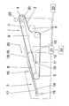
- a belt table 1 with a downstream feed table 2 is shown schematically in side view.
- the belt table 1 has at least one suction belt 3, which is guided over an upper deflecting roller 4 and a lower deflecting roller 5 and tensioned by means of two rollers 6.
- a sheet feeder not shown, facing suction box 7 and a lower, also not shown bow-processing machine facing suction box 8 is arranged. Between the suction boxes 7, 8 more suction boxes can be arranged.
- the upper suction box 7 is connected via a suction nozzle 9 with a first vacuum source, not shown, and the lower suction box 8 via a suction nozzle 10 with a second vacuum source, not shown.
- a suction nozzle 10 opening or closing actuator 11 is arranged at the suction nozzle 10 .
- a ventilation flap 12 is further provided, which can be actuated by means of an adjusting device 13.
- the belt table 1 is followed by the feed table 2, of which a table top 14 is shown. In your position on the feed table 2 leading marks 15 are shown.
- the front marks 15 can be spent in the working cycle from the position on the feed table 2 in a pivoted-away from the feed table 2 position. Adjacent to the front marks 15, a sheet 17 to be aligned, to which a following sheet 18 is arranged downstream as the last sheet 19, is shown.
- a double-sheet control 16 is further provided, while the upper guide roller 4 is assigned a cyclically operating swab roller 23.
- the drive of the suction belt 3 in a sheet transport direction 25 is effected by a drive unit 20 assigned to the upper deflection roller 5.
- the drive unit 20 is connected to a control unit 21 which is linked to the setting unit 11, the setting device 13 and the double sheet control 16.
- Also connected to the control unit 21 are the machine controller 22 and an input unit 24.
- the sheets separated by the sheet feeder are fed to the belt table 1 under suction and are picked up by the suction belt 3, supported by the swab roller 23 guided in the working cycle against the upper deflection roller 4.
- the holding force acting on the sheet is realized by the negative pressure built up in the upper suction box 7 by means of the vacuum source connected to the suction nozzle 9.
- the sheets are conveyed as a sheet flow from the suction belt 3, driven by the drive unit 20, in the sheet transport direction 25, wherein the respective foremost sheet of the sheet flow is transported as bow 17 ausuinfoder on the feed table 2 and with the front edge against the front marks 15.
- the force acting on the sheet 17 to be aligned, initiated by means of the pressure prevailing in the lower suction box 8 negative pressure holding force is minimized by the underlap of the subsequent sheet 18 or completely canceled.
- the sheet 17 to be aligned can be easily applied to the front marks 15 and subsequently also aligned, if necessary, according to the side edge.
- the sheet 17 After aligning the sheet 17 is withdrawn by means not shown and transported to the downstream sheet-processing machine. Simultaneously with the removal of the sheet 17 to be aligned, the follower sheet 18 is conveyed in the sheet transport direction 25. If a single arc is detected by the double sheet control 16 as a function of the position on the belt table 1 and the stagger spacing of the undercut arc current instead of a double or triple arc, this is detected as the last arc of the arc current and generates a signal. It is advantageous to assign the double-sheet control 16 to the belt table 1 in such a way that it detects the sheet 17 / subsequent sheet 18 or another sheet to be aligned with the underlap. The signal generated by the double-sheet control 16 is supplied to the control unit 21.
- the last sheet 19 is detected and found in the control unit 21, the number of located between the front lays 15 and the last sheet 19 bow or the number of work cycles, which must be realized until the last sheet 19 rests as bow 17 ausuzinder to the front marks 15. If the sheet designated in the figurative representation as a follower sheet 18 is identified as the last sheet 19, the follower sheet 18 / last sheet 19 is transported against the leading marks 15 during the removal of the sheet 17 to be aligned by means of a sheet feeder, not shown. In this case, controlled by the control unit 21, the drive unit 20 is stopped, and thus the movement of the suction belt 3 is interrupted when the leading edge of the determined as last sheet 19 subsequent sheet 18 applies to the front marks 15.
- the drive unit 20 can be stopped so that the last sheet 19 applies with a lower suppression of the front marks 15. Simultaneously or immediately before the application or within the power stroke, in which the transport of the last sheet 19, the vacuum supply to the lower suction box 8 is interrupted by the control unit 21 by means of the adjusting unit 11 and the venting flap 12 is opened by the adjusting device 13. Thus, the last sheet 19 can be aligned to the side edge and subsequently withdrawn.
- the interruption of the vacuum supply by means of the adjusting unit 11 to the lower suction box 8 and the opening of the venting flap 12 by the adjusting device 13 is arbitrarily within the working cycle, in which the last sheet 19 is transported to the front lays 15, via the input unit 24 possible.
- the release of the last sheet 19 can be adjusted depending on the material to be processed or on the design of the sheet system. For example, in a sheet feeder where side edge alignment is provided on the feed table 2 after alignment with respect to the leading edge, the ventilation of the lower suction box 8 must be earlier than in a sheet feeder with side edge alignment on a downstream cylinder.
- the last bend 19 and its position on the belt table are detected by the double-sheet control 16. It is also possible to detect the final arc 19 by additional means.
- the last sheet 19 and thus the sheet located on the feed table 1 / belt table 2 before this can be detected by the machine control.
Abstract
Description
Die Erfindung betrifft eine Vorrichtung zum Zuführen eines geschuppten Bogenstromes von einem Bogenstapel eines Bogenanlegers zu einem Anlegtisch einer bogenverarbeitenden Maschine mit einem Bändertisch, der mit mindestens einem umlaufend angetriebenen Saugband versehen ist, das mit mindestens zwei hintereinander mit Saugluft beaufschlagbaren Saugkästen in Wirkverbindung steht, sowie mit Mitteln zum Erfassen der Bogen.The invention relates to a device for supplying a scaly arc stream from a sheet pile of a sheet feeder to a feed table of a sheet processing machine Machine with a belt table, with at least one revolving driven Suction belt is provided with at least two consecutively with suction acted upon suction boxes in operative connection, as well as with means for detecting the arc.
Derartige Vorrichtungen sind allgemein bekannt. Die durch einen Bogenanleger von einem Bogenstapel vereinzelten Bogen werden als geschuppter Bogenstrom auf einem Saugbänder aufweisenden Bändertisch transportiert, dort von den Saugbändern erfasst und zum Anlegtisch transportiert. Dabei werden die Saugbänder im Bereich der Bogenübernahme von einem dem Bogenanleger zugewandten Saugkasten unterdruckbeaufschlagt, während im Bereich der Bogenübergabe auf den Anlegtisch die Saugbänder durch einen der Maschine zugewandten Saugkasten mit Unterdruck beaufschlagt werden. Der jeweils vorderste Bogen des Bogenstroms wird auf dem Anlegtisch mit der Vorderkante gegen Vordermarken geführt und so nach der Vorderkante ausgerichtet. Nachfolgend wird der Bogen z.B. nach der Seitenkante ausgerichtet. Beim Ausrichten des jeweils vordersten Bogens darf dieser durch die Saugbänder nur mit einer solchen Haltekraft geführt werden, dass beim Anlegen des Bogens an die Vordermarken die Vorderkante nicht beschädigt wird und eine Seitenausrichtung problemlos möglich ist. Das wird dadurch ermöglicht, dass durch den unterschuppt angeordneten Folgebogen die Saugbänder vollständig oder nahe vollständig abgedeckt werden, so dass der auszurichtende Bogen nur mit einer geringen Haltekraft im Übergabebereich geführt wird. Fehlt ein Folgebogen, wenn z.B. der Bogenstrom unterbrochen wird, wirkt auf den letzten auszurichtenden Bogen eine solche Haltkraft, dass bei der Verarbeitung von Papier die Gefahr einer Beschädigung der Bogenvorderkante besteht bzw. eine exakte Seitenausrichtung nicht möglich ist.Such devices are well known. The one by a sheet feeder of one Sheet pile isolated sheets are seen as shingled stream stream on one Transported belt table having suction belts, there detected by the suction belts and transported to the feed table. The suction belts are in the area of sheet transfer pressurized by a suction box facing the sheet feeder, while in the area of sheet transfer to the feed table, the suction belts be subjected to negative pressure by one of the machine-facing suction box. The respective foremost arc of the sheet flow is on the feed table with the leading edge guided against leading brands and so aligned to the front edge. following If the bow is e.g. aligned to the side edge. When aligning each Foremost bow may this led by the suction belts only with such a holding force be that when creating the sheet to the front marks the leading edge is not is damaged and a page orientation is easily possible. That's going to happen allows the suction belts to be completely opened by the lower-lying following bend or close completely covered, so that the bow to be aligned only is performed with a low holding force in the transfer area. Missing a follow-up sheet, if e.g. the arc current is interrupted acts on the last sheet to be aligned such a holding force that when processing paper carries the risk of damage the sheet leading edge exists or an exact page orientation is not possible is.
Um diesen Nachteil zu beseitigen, wird in der EP 0 554 774 B1 vorgeschlagen, die Zufuhr
des letzten Bogens des Bogenstroms zu erfassen. Nachdem der vorletzte Bogen abgezogen
worden ist, wird die Unterdruckzufuhr zum der Maschine zugewandten Saugkasten
unterbrochen und dieser mit einer Überdrückquelle verbunden.
Diese Vorrichtung ist im Dünndruckbereich nicht anwendbar, da eine definierte Führung
des letzten Bogens zu den Vordermarken nicht gegeben ist. In order to eliminate this disadvantage, it is proposed in EP 0 554 774 B1 to detect the supply of the last arc of the arc current. After the penultimate sheet has been withdrawn, the vacuum supply to the machine facing suction box is interrupted and connected to an overpressure source.
This device is not applicable in the thin pressure range, since a defined guidance of the last sheet is not given to the leading brands.
Aufgabe der Erfindung ist es, eine gattungsgemäße Vorrichtung so zu verändern, dass unabhängig vom zur Verarbeitung gelangenden Material auch der letzte Bogen eines Bogenstroms problemlos ausgerichtet wird.The object of the invention is to modify a generic device so that regardless of the material to be processed, even the last arc of a sheet flow is easily aligned.
Erfindungsgemäß wird die Aufgabe durch eine Vorrichtung nach den Merkmalen des Anspruchs 1 gelöst.According to the invention the object is achieved by a device according to the features of Claim 1 solved.
Die erfindungsgemäße Lösung ermöglicht es, den letzten Bogen eines geschuppten Bogenstromes unabhängig von der Materialbeschaffenheit definiert an den Vordermarken anzulegen. Damit wird sichergestellt, dass das gesamte zur Verarbeitung gelangende Material störungsfrei verarbeitet werden kann.The solution according to the invention makes it possible, the last arc of a scaly arc stream regardless of the material condition defined on the front lays to apply. This will ensure that the entire process gets processed Material can be processed trouble-free.
An einem Ausführungsbeispiel wird die Erfindung näher erläutert. In der zugehörigen
Zeichnung ist ein Bändertisch 1 mit einem nachgeordneten Anlegtisch 2 schematisch in
Seitenansicht dargestellt. Der Bändertisch 1 weist mindestens ein Saugband 3 auf, das
über eine obere Umlenkwalze 4 und eine untere Umlenkwalze 5 geführt sowie mittels
zweier Walzen 6 gespannt wird. Im Bändertisch 1 ist ein oberer, einem nicht dargestellten
Bogenanleger zugewandter Saugkasten 7 und ein unterer, einer ebenfalls nicht dargestellten
bogenverarbeitenden Maschine zugewandter Saugkasten 8 angeordnet. Zwischen
den Saugkästen 7, 8 können weitere Saugkästen angeordnet sein. Der obere
Saugkasten 7 ist über einen Saugstutzen 9 mit einer nicht dargestellten ersten Unterdruckquelle
und der untere Saugkasten 8 über einen Saugstutzen 10 mit einer nicht dargestellten
zweiten Unterdruckquelle verbunden. Am Saugstutzen 10 ist eine den Saugstutzen
10 öffnende oder schließende Stelleinheit 11 angeordnet. Am unteren Saugkasten
8 ist weiterhin eine Entlüftungsklappe 12 vorgesehen, die mittels einer Stelleinrichtung 13
betätigt werden kann.
Dem Bändertisch 1 ist der Anlegtisch 2 nachgeordnet, von dem ein Tischblech 14 gezeigt
ist. In Ihrer Position am Anlegtisch 2 sind Vordermarken 15 dargestellt. Die Vordermarken
15 können im Arbeitstakt aus der Position am Anlegtisch 2 in eine vom Anlegtisch 2 abgeschwenkte
Position verbracht werden. An den Vordermarken 15 anliegend, ist ein auszurichtender
Bogen 17, dem ein Folgebogen 18 als Letztbogen 19 nachgeordnet ist, dargestellt.
Vor der unteren Umlenkwalze 5 ist weiterhin eine Doppelbogenkontrolle 16 vorgesehen,
während der oberen Umlenkwalze 4 eine taktweise arbeitende Tupferwalze 23
zugeordnet ist. Der Antrieb des Saugbandes 3 in eine Bogentransportrichtung 25 erfolgt
durch eine der oberen Umlenkwalze 5 zugeordnete Antriebseinheit 20. Die Antriebseinheit
20 ist verbunden mit einer Steuereinheit 21, die mit der Stelleinheit 11, der Stelleinrichtung
13 und der Doppelbogenkontrolle 16 verknüpft ist. Mit der Steuereinheit 21 sind auch
die Maschinensteuerung 22 und eine Eingabeeinheit 24 verbunden.
Die vom Bogenanleger vereinzelten Bogen werden unterschuppt dem Bändertisch 1 zugeführt
und vom Saugband 3, unterstützt durch die im Arbeitstakt gegen die obere Umlenkwalze
4 geführte Tupferwalze 23, erfasst. Die auf die Bogen wirkende Haltekraft wird
realisiert durch den im oberen Saugkasten 7 mittels der mit dem Saugstutzen 9 verbundenen
Unterdruckquelle aufgebauten Unterdruck. Die Bogen werden als Bogenstrom von
dem Saugband 3, angetrieben durch die Antriebseinheit 20, in Bogentransportrichtung 25
gefördert, wobei der jeweils vorderste Bogen des Bogenstromes als auszurichtender Bogen
17 auf den Anlegtisch 2 und mit der Vorderkante gegen die Vordermarken 15 transportiert
wird. Dabei wird die auf den auszurichtenden Bogen 17 wirkende, mit Hilfe des im
unteren Saugkastens 8 herrschenden Unterdrucks initiierte Haltekraft durch die Unterlappung
des Folgebogens 18 minimiert oder vollständig aufgehoben. Dadurch kann der auszurichtende
Bogen 17 problemlos an den Vordermarken 15 angelegt und nachfolgend
ebenso ggf. nach der Seitenkante ausgerichtet werden. Nach dem ausrichten wird der
Bogen 17 durch nicht dargestellte Mittel abgezogen und in die nachgeordnete bogenverarbeitende
Maschine transportiert. Gleichzeitig mit dem Abziehen des auszurichtenden
Bogens 17 wird der Folgebogen 18 in Bogentransportrichtung 25 gefördert.
Wird von der Doppelbogenkontrolle 16 in Abhängigkeit von der Position auf dem Bändertisch
1 sowie des Staffelabstandes des unterlappten Bogenstroms statt eines Doppel-oder
Dreifachbogens ein Einfachbogen detektiert, so wird dieser als letzter Bogen des
Bogenstromes erkannt und ein Signal generiert. Dabei ist es vorteilhaft, die Doppelbogenkontrolle
16 so dem Bändertisch 1 zuzuordnen, dass diese die Unterlappung auszurichtender
Bogen 17/Folgebogen 18 bzw. eines weiteren Bogens erfasst.
Das von der Doppelbogenkontrolle 16 generierte Signal wird der Steuereinheit 21 zugeführt.
Damit wird der Letztbogen 19 erkannt und in der Steuereinheit 21 die Anzahl der
zwischen den Vordermarken 15 und dem Letztbogen 19 befindlichen Bogen bzw. die Anzahl
Arbeitstakte festgestellt, die realisiert werden müssen, bis der Letztbogen 19 als auszurichtender
Bogen 17 an den Vordermarken 15 anliegt. Wird der in der figürlichen Darstellung
als Folgebogen 18 bezeichnete Bogen als Letztbogen 19 festgestellt, wird während
des Abziehens des auszurichtenden Bogens 17 mittels einer nicht dargestellten Bogenzuführeinrichtung
der Folgebogen 18/Letztbogen 19 gegen die Vordermarken 15
transportiert. Dabei wird, gesteuert durch die Steuereinheit 21, die Antriebseinheit 20 gestoppt
und damit die Bewegung des Saugbandes 3 unterbrochen, wenn die Vorderkante
des als Letztbogen 19 ermittelten Folgebogens 18 an den Vordermarken 15 anlegt. Dabei
kann die Antriebseinheit 20 so gestoppt werden, dass der Letztbogen 19 mit einer geringeren
Überdrückung an den Vordermarken 15 anlegt. Gleichzeitig oder unmittelbar vor
dem Anlegen bzw. innerhalb des Arbeitstaktes, in dem der Transport des Letztbogens 19
erfolgt, wird über die Steuereinheit 21 die Unterdruckzufuhr zum unteren Saugkasten 8
mittels der Stelleinheit 11 unterbrochen und die Entlüftungsklappe 12 durch die Stelleinrichtung
13 geöffnet. Damit kann der Letztbogen 19 nach der Seitenkante ausgerichtet
und nachfolgend abgezogen werden.
Das Unterbrechen der Unterdruckzufuhr mittels der Stelleinheit 11 zum unteren Saugkasten
8 und das öffnen der Entlüftungsklappe 12 durch die Stelleinrichtung 13 ist beliebig
innerhalb des Arbeitstaktes, in dem der Letztbogen 19 zu den Vordermarken 15 transportiert
wird, über die Eingabeeinheit 24 möglich. Damit kann die Freigabe des Letztbogens
19 in Abhängigkeit vom zur Verarbeitung gelangenden Material oder von der Ausgestaltung
der Bogenanlage angepasst werden. So muss z.B. in einer Bogenanlage, bei der
nach dem Ausrichten bezüglich der Vorderkante eine Seitenkantenausrichtung auf dem
Anlegtisch 2 vorgesehen ist, die Belüftung des unteren Saugkastens 8 früher erfolgen als
bei einer Bogenanlage mit einer Seitenkantenausrichtung auf einem nachgeordneten Zylinder.
Im Ausführungsbeispiel wird beschrieben, dass der Letztbogen 19 sowie seine Position
auf dem Bändertisch durch die Doppelbogenkontrolle 16 erfasst wird. Es ist auch möglich,
durch zusätzliche Mittel den Letztbogen 19 zu erfassen. Außerdem können die Letztbogen
19 und damit die auf dem Anlegtisch 1/Bändertisch 2 vor diesem befindlichen Bogen
durch die Maschinensteuerung erfasst werden. In one embodiment, the invention is explained in detail. In the accompanying drawing, a belt table 1 with a downstream feed table 2 is shown schematically in side view. The belt table 1 has at least one
The belt table 1 is followed by the feed table 2, of which a
The sheets separated by the sheet feeder are fed to the belt table 1 under suction and are picked up by the
If a single arc is detected by the
The signal generated by the double-
The interruption of the vacuum supply by means of the adjusting
In the exemplary embodiment, it is described that the last bend 19 and its position on the belt table are detected by the double-
- 11
- Bändertischbelt table
- 22
- Anlegtischfeed table
- 33
- Saugbandsuction belt
- 44
- obere Umlenkwalzeupper guide roller
- 55
- untere Umlenkwalzelower deflection roller
- 66
- Walzeroller
- 77
- oberer Saugkastenupper suction box
- 88th
- unterer Saugkastenlower suction box
- 99
- Saugstutzensuction
- 1010
- Saugstutzensuction
- 1111
- Stelleinheitactuator
- 1212
- Entlüftungsklappevent flap
- 1313
- Stelleinrichtungsetting device
- 1414
- Tischblechtable sheet
- 1515
- Vordermarkefront lay
- 1616
- DoppelbogenkontrolleDouble sheet control
- 1717
- Auszurichtender BogenBow to be straightened
- 1818
- Folgebogenepisode arc
- 1919
- Letztbogenlast bow
- 2020
- Antriebseinheitdrive unit
- 2121
- Steuereinheitcontrol unit
- 2222
- Maschinensteuerungmachine control
- 2323
- Tupferwalzeswab roll
- 2424
- Eingabeeinheitinput unit
- 2525
- BogentransportrichtungSheet transport direction
Claims (9)
Applications Claiming Priority (2)
| Application Number | Priority Date | Filing Date | Title |
|---|---|---|---|
| DE102004015335A DE102004015335A1 (en) | 2004-03-30 | 2004-03-30 | Apparatus for feeding a scaly arc stream |
| DE102004015335 | 2004-03-30 |
Publications (2)
| Publication Number | Publication Date |
|---|---|
| EP1582490A1 true EP1582490A1 (en) | 2005-10-05 |
| EP1582490B1 EP1582490B1 (en) | 2008-05-07 |
Family
ID=34877641
Family Applications (1)
| Application Number | Title | Priority Date | Filing Date |
|---|---|---|---|
| EP05004412A Expired - Fee Related EP1582490B1 (en) | 2004-03-30 | 2005-03-01 | Device for feeding a stream of overlapping sheets |
Country Status (3)
| Country | Link |
|---|---|
| US (1) | US7401777B2 (en) |
| EP (1) | EP1582490B1 (en) |
| DE (2) | DE102004015335A1 (en) |
Cited By (2)
| Publication number | Priority date | Publication date | Assignee | Title |
|---|---|---|---|---|
| DE102007036134A1 (en) * | 2007-08-01 | 2009-02-05 | Koenig & Bauer Aktiengesellschaft | Adjustable device to feed sheets in scaled sequence to printing press has timer stoppable at maximum or minimum pressure level in suction box |
| CN110982164A (en) * | 2013-10-15 | 2020-04-10 | 巴塞尔聚烯烃股份有限公司 | Polyethylene for injection moulding |
Families Citing this family (4)
| Publication number | Priority date | Publication date | Assignee | Title |
|---|---|---|---|---|
| DE102005057361A1 (en) * | 2005-12-01 | 2007-06-06 | Koenig & Bauer Ag | Under-lapped sheet flow conveying device, has suction belt drivable in speed characteristics during transport of last sheet of sequence of sheets on feed table, where speed characteristics exhibit rest with transport speed equal to zero |
| DE102016212712B4 (en) | 2016-07-13 | 2019-01-31 | Koenig & Bauer Ag | sheet feeder |
| DE102016015729A1 (en) | 2016-07-13 | 2018-01-18 | Koenig & Bauer Ag | sheet feeder |
| DE102022112361B3 (en) | 2022-05-17 | 2023-04-06 | Koenig & Bauer Ag | Sheet feeder for a sheet processing machine |
Citations (4)
| Publication number | Priority date | Publication date | Assignee | Title |
|---|---|---|---|---|
| US4651984A (en) * | 1983-09-02 | 1987-03-24 | M.A.N.-Roland Druckmaschinen Aktiengesellschaft | Method of and apparatus for accurate-register sheet transport in a printing machine |
| EP0554774A1 (en) * | 1992-02-07 | 1993-08-11 | MAN Roland Druckmaschinen AG | Device for forwarding a stream overlapping sheets |
| DE4442629A1 (en) * | 1994-12-01 | 1996-06-05 | Heidelberger Druckmasch Ag | Suction band feed table for sheets of paper |
| EP1155996A2 (en) * | 2000-04-06 | 2001-11-21 | LTG Mailänder GmbH | Device and method for feeding articles |
Family Cites Families (6)
| Publication number | Priority date | Publication date | Assignee | Title |
|---|---|---|---|---|
| US3826487A (en) * | 1972-01-24 | 1974-07-30 | Polygraph Leipzig | Control apparatus and method for transporting sheets |
| DE4416286C2 (en) * | 1994-05-07 | 1999-10-28 | Heidelberger Druckmasch Ag | Device for adjusting the negative pressure in a suction belt feed table of a sheet feeder |
| DE19505560C2 (en) * | 1995-02-18 | 1998-07-02 | Roland Man Druckmasch | Procedure for controlling sheet feeding |
| DE19618870A1 (en) * | 1996-05-10 | 1997-11-13 | Heidelberger Druckmasch Ag | Device for conveying an in particular flaky stream of sheets to a sheet processing machine |
| DE19817175A1 (en) * | 1997-09-19 | 1999-03-25 | Heidelberger Druckmasch Ag | Device to deliver especially ragged flow of paper sheets to processing machine |
| DE10021629A1 (en) * | 1999-05-28 | 2000-11-30 | Heidelberger Druckmasch Ag | Multi sheet feed unit has a contact roller that is adjustable and includes a tripped switch |
-
2004
- 2004-03-30 DE DE102004015335A patent/DE102004015335A1/en not_active Withdrawn
-
2005
- 2005-03-01 DE DE502005003941T patent/DE502005003941D1/en active Active
- 2005-03-01 EP EP05004412A patent/EP1582490B1/en not_active Expired - Fee Related
- 2005-03-18 US US11/083,910 patent/US7401777B2/en not_active Expired - Fee Related
Patent Citations (4)
| Publication number | Priority date | Publication date | Assignee | Title |
|---|---|---|---|---|
| US4651984A (en) * | 1983-09-02 | 1987-03-24 | M.A.N.-Roland Druckmaschinen Aktiengesellschaft | Method of and apparatus for accurate-register sheet transport in a printing machine |
| EP0554774A1 (en) * | 1992-02-07 | 1993-08-11 | MAN Roland Druckmaschinen AG | Device for forwarding a stream overlapping sheets |
| DE4442629A1 (en) * | 1994-12-01 | 1996-06-05 | Heidelberger Druckmasch Ag | Suction band feed table for sheets of paper |
| EP1155996A2 (en) * | 2000-04-06 | 2001-11-21 | LTG Mailänder GmbH | Device and method for feeding articles |
Cited By (3)
| Publication number | Priority date | Publication date | Assignee | Title |
|---|---|---|---|---|
| DE102007036134A1 (en) * | 2007-08-01 | 2009-02-05 | Koenig & Bauer Aktiengesellschaft | Adjustable device to feed sheets in scaled sequence to printing press has timer stoppable at maximum or minimum pressure level in suction box |
| DE102007036134B4 (en) * | 2007-08-01 | 2019-01-17 | Koenig & Bauer Ag | Adaptable to the substrate device for feeding sheets in a shingled sequence |
| CN110982164A (en) * | 2013-10-15 | 2020-04-10 | 巴塞尔聚烯烃股份有限公司 | Polyethylene for injection moulding |
Also Published As
| Publication number | Publication date |
|---|---|
| DE502005003941D1 (en) | 2008-06-19 |
| DE102004015335A1 (en) | 2005-10-20 |
| US20050230905A1 (en) | 2005-10-20 |
| EP1582490B1 (en) | 2008-05-07 |
| US7401777B2 (en) | 2008-07-22 |
Similar Documents
| Publication | Publication Date | Title |
|---|---|---|
| EP1880960B1 (en) | Device for feeding a stream of overlapping sheets | |
| EP1582490B1 (en) | Device for feeding a stream of overlapping sheets | |
| DE102004007404B4 (en) | Sheet trailing edge lift | |
| DE102009027389B4 (en) | Arrangement for the lateral alignment of sheets | |
| EP1593626B1 (en) | Front edge feeder | |
| EP1739039A2 (en) | Method and device for transporting sheets to a printing machine | |
| DE102006025074A1 (en) | Sheets transporting and feeding method for printing press, involves aligning sheet along transport direction by simultaneous acceleration or deceleration of driven carrier in parallel movement paths | |
| EP2135743B1 (en) | Method for controlling sheet supply | |
| DE102020124433A1 (en) | Feeder of a sheet-processing machine and method for supporting sheet separation in a feeder of a sheet-processing machine | |
| DE102008054813A1 (en) | Device for aligning of sheets, has cam lifter and individual sheet in conveying device in towing lifter transporting sheet transport unit | |
| EP1593625B1 (en) | Leading edge feeder | |
| DE102006061429B4 (en) | Method of feeding a shingled arc stream | |
| DE10315192A1 (en) | Lateral alignment device for sheets in sheet handing machine such as printing machine, has lateral pull-lays which are activated to pull sheet left or right depending on alignment position | |
| DE102014210110A1 (en) | Feeder for a sheet-fed printing machine and method for operating such an investor | |
| DE19643600A1 (en) | Paper sheet transport system for printing press | |
| DE10033490B4 (en) | Device for laterally aligning bows | |
| EP1352862B1 (en) | Method for selectively feeding sheets or advance-sheets | |
| DE10010057A1 (en) | Method and appliance for controlling vacuum level comprises suction pulling rail, rotary valve, control groove, ventilation opening and connecting openings. | |
| DE10106669A1 (en) | Sheet stacking device for printing machine delivery unit has sensor in sheet front-edge stop plate and controls actuators to influence sheet arrival | |
| DE102015204558B4 (en) | Device for aligning sheets | |
| DE102004012697A1 (en) | Sheet feeding method for sheet processing machine, involves subsequently gripping sheet with further transport device after smoothing leading edge of sheet by imparting curvature to sheet in sheet transport direction | |
| DE102019133574B4 (en) | Suction chamber arrangement for lateral sheet registration | |
| DE102020107837B4 (en) | Sheet processing machine with a sheet separator | |
| DE102008036232A1 (en) | Sheet supplying method for sheet processing machine, involves attaching belt single drive to belt table, and changing shingle distance depending on operating speed of sheet processing machine | |
| DE102017221217B4 (en) | Sheet processing machine |
Legal Events
| Date | Code | Title | Description |
|---|---|---|---|
| PUAI | Public reference made under article 153(3) epc to a published international application that has entered the european phase |
Free format text: ORIGINAL CODE: 0009012 |
|
| AK | Designated contracting states |
Kind code of ref document: A1 Designated state(s): AT BE BG CH CY CZ DE DK EE ES FI FR GB GR HU IE IS IT LI LT LU MC NL PL PT RO SE SI SK TR |
|
| AX | Request for extension of the european patent |
Extension state: AL BA HR LV MK YU |
|
| 17P | Request for examination filed |
Effective date: 20050812 |
|
| AKX | Designation fees paid |
Designated state(s): DE FR IT |
|
| 17Q | First examination report despatched |
Effective date: 20070601 |
|
| GRAP | Despatch of communication of intention to grant a patent |
Free format text: ORIGINAL CODE: EPIDOSNIGR1 |
|
| GRAS | Grant fee paid |
Free format text: ORIGINAL CODE: EPIDOSNIGR3 |
|
| GRAA | (expected) grant |
Free format text: ORIGINAL CODE: 0009210 |
|
| AK | Designated contracting states |
Kind code of ref document: B1 Designated state(s): DE FR IT |
|
| REF | Corresponds to: |
Ref document number: 502005003941 Country of ref document: DE Date of ref document: 20080619 Kind code of ref document: P |
|
| PLBE | No opposition filed within time limit |
Free format text: ORIGINAL CODE: 0009261 |
|
| STAA | Information on the status of an ep patent application or granted ep patent |
Free format text: STATUS: NO OPPOSITION FILED WITHIN TIME LIMIT |
|
| 26N | No opposition filed |
Effective date: 20090210 |
|
| REG | Reference to a national code |
Ref country code: DE Ref legal event code: R081 Ref document number: 502005003941 Country of ref document: DE Owner name: KOENIG & BAUER AG, DE Free format text: FORMER OWNER: KOENIG & BAUER AKTIENGESELLSCHAFT, 97080 WUERZBURG, DE |
|
| REG | Reference to a national code |
Ref country code: FR Ref legal event code: PLFP Year of fee payment: 12 |
|
| PGFP | Annual fee paid to national office [announced via postgrant information from national office to epo] |
Ref country code: FR Payment date: 20160328 Year of fee payment: 12 |
|
| PGFP | Annual fee paid to national office [announced via postgrant information from national office to epo] |
Ref country code: IT Payment date: 20160331 Year of fee payment: 12 |
|
| REG | Reference to a national code |
Ref country code: FR Ref legal event code: ST Effective date: 20171130 |
|
| PG25 | Lapsed in a contracting state [announced via postgrant information from national office to epo] |
Ref country code: FR Free format text: LAPSE BECAUSE OF NON-PAYMENT OF DUE FEES Effective date: 20170331 |
|
| PG25 | Lapsed in a contracting state [announced via postgrant information from national office to epo] |
Ref country code: IT Free format text: LAPSE BECAUSE OF NON-PAYMENT OF DUE FEES Effective date: 20170301 |
|
| PGFP | Annual fee paid to national office [announced via postgrant information from national office to epo] |
Ref country code: DE Payment date: 20200302 Year of fee payment: 16 |
|
| REG | Reference to a national code |
Ref country code: DE Ref legal event code: R119 Ref document number: 502005003941 Country of ref document: DE |
|
| PG25 | Lapsed in a contracting state [announced via postgrant information from national office to epo] |
Ref country code: DE Free format text: LAPSE BECAUSE OF NON-PAYMENT OF DUE FEES Effective date: 20211001 |