EP1582157A1 - Medizinisches Instrument zum Präparieren von Gewebe - Google Patents
Medizinisches Instrument zum Präparieren von Gewebe Download PDFInfo
- Publication number
- EP1582157A1 EP1582157A1 EP05012958A EP05012958A EP1582157A1 EP 1582157 A1 EP1582157 A1 EP 1582157A1 EP 05012958 A EP05012958 A EP 05012958A EP 05012958 A EP05012958 A EP 05012958A EP 1582157 A1 EP1582157 A1 EP 1582157A1
- Authority
- EP
- European Patent Office
- Prior art keywords
- shaft
- tool
- movable
- bend
- transmission element
- Prior art date
- Legal status (The legal status is an assumption and is not a legal conclusion. Google has not performed a legal analysis and makes no representation as to the accuracy of the status listed.)
- Granted
Links
- 230000005540 biological transmission Effects 0.000 claims description 58
- 239000011343 solid material Substances 0.000 claims description 5
- 241001465754 Metazoa Species 0.000 claims description 4
- 238000000034 method Methods 0.000 claims description 4
- 239000007787 solid Substances 0.000 claims description 2
- 210000001519 tissue Anatomy 0.000 description 14
- 238000005452 bending Methods 0.000 description 9
- GUIJLPKNGJMXKV-AZUAARDMSA-N rod-188 Chemical compound C1=CC(C)=CC=C1S(=O)(=O)N1[C@@H]([C@H]2OC(=O)CC2)C2=CC=CC=C2CC1 GUIJLPKNGJMXKV-AZUAARDMSA-N 0.000 description 5
- 238000004519 manufacturing process Methods 0.000 description 4
- 238000005520 cutting process Methods 0.000 description 3
- 238000003466 welding Methods 0.000 description 3
- 238000005516 engineering process Methods 0.000 description 2
- 210000001214 frontal sinus Anatomy 0.000 description 2
- 239000000463 material Substances 0.000 description 2
- 210000004086 maxillary sinus Anatomy 0.000 description 2
- 238000002324 minimally invasive surgery Methods 0.000 description 2
- 238000004080 punching Methods 0.000 description 2
- 125000006850 spacer group Chemical group 0.000 description 2
- 229910000639 Spring steel Inorganic materials 0.000 description 1
- 238000004026 adhesive bonding Methods 0.000 description 1
- 210000000988 bone and bone Anatomy 0.000 description 1
- 210000000845 cartilage Anatomy 0.000 description 1
- 238000011109 contamination Methods 0.000 description 1
- 230000003292 diminished effect Effects 0.000 description 1
- 238000002224 dissection Methods 0.000 description 1
- 239000013013 elastic material Substances 0.000 description 1
- 210000003811 finger Anatomy 0.000 description 1
- 210000005224 forefinger Anatomy 0.000 description 1
- 238000002955 isolation Methods 0.000 description 1
- 239000007788 liquid Substances 0.000 description 1
- 210000001331 nose Anatomy 0.000 description 1
- 230000035515 penetration Effects 0.000 description 1
- 238000002360 preparation method Methods 0.000 description 1
- 238000010926 purge Methods 0.000 description 1
- 238000009751 slip forming Methods 0.000 description 1
- IHQKEDIOMGYHEB-UHFFFAOYSA-M sodium dimethylarsinate Chemical class [Na+].C[As](C)([O-])=O IHQKEDIOMGYHEB-UHFFFAOYSA-M 0.000 description 1
- 238000005476 soldering Methods 0.000 description 1
- 241000894007 species Species 0.000 description 1
- 238000001356 surgical procedure Methods 0.000 description 1
- 210000003813 thumb Anatomy 0.000 description 1
- 238000011179 visual inspection Methods 0.000 description 1
Images

Classifications
-
- A—HUMAN NECESSITIES
- A61—MEDICAL OR VETERINARY SCIENCE; HYGIENE
- A61B—DIAGNOSIS; SURGERY; IDENTIFICATION
- A61B17/00—Surgical instruments, devices or methods
- A61B17/16—Instruments for performing osteoclasis; Drills or chisels for bones; Trepans
- A61B17/1604—Chisels; Rongeurs; Punches; Stamps
- A61B17/1606—Chisels; Rongeurs; Punches; Stamps of forceps type, i.e. having two jaw elements moving relative to each other
- A61B17/1608—Chisels; Rongeurs; Punches; Stamps of forceps type, i.e. having two jaw elements moving relative to each other the two jaw elements being linked to two elongated shaft elements moving longitudinally relative to each other
- A61B17/1611—Chisels; Rongeurs; Punches; Stamps of forceps type, i.e. having two jaw elements moving relative to each other the two jaw elements being linked to two elongated shaft elements moving longitudinally relative to each other the two jaw elements being integral with respective elongate shaft elements
-
- A—HUMAN NECESSITIES
- A61—MEDICAL OR VETERINARY SCIENCE; HYGIENE
- A61B—DIAGNOSIS; SURGERY; IDENTIFICATION
- A61B17/00—Surgical instruments, devices or methods
- A61B17/28—Surgical forceps
- A61B17/29—Forceps for use in minimally invasive surgery
- A61B2017/2901—Details of shaft
- A61B2017/2902—Details of shaft characterized by features of the actuating rod
-
- A—HUMAN NECESSITIES
- A61—MEDICAL OR VETERINARY SCIENCE; HYGIENE
- A61B—DIAGNOSIS; SURGERY; IDENTIFICATION
- A61B17/00—Surgical instruments, devices or methods
- A61B17/28—Surgical forceps
- A61B17/29—Forceps for use in minimally invasive surgery
- A61B2017/2901—Details of shaft
- A61B2017/2904—Details of shaft curved, but rigid
Definitions
- the invention relates to a medical instrument for dissection tissue in the human or animal body the preamble of claim 1.
- An instrument for tissue preparation is an instrument for separating and / or grasping tissue, for example, a punch, scissors or pliers.
- Such instruments are used in the context of minimally invasive Surgery used tissue in human or animal Body, usually under endoscopic visual inspection, separate.
- such instruments have a long extended shaft, at the distal end at least one movable tool is arranged, usually with another movable or immovable tool on distal end of the shaft cooperates to separate the tissue.
- Such instruments also have at the proximal end of At least one movable grip on the handle on thrust and / or train working axially movable power transmission element frictionally with the at least one movable Tool is connected, allowing a movement of the movable Handle part of the power transmission element in a movement of the movable tool is transmitted.
- nose and throat are used instruments whose shaft at least has a bend around the tool (s) at the distal end End in hard-to-reach places, for example in niches the frontal or maxillary sinus, to be able to bring.
- the force transmission element In order to adapt to the bend, the force transmission element must therefore in the area of the bend of the shaft one Have bending elasticity.
- a force transmission element for a medical instrument in the form of a flexural elastic wire member disclosed to such Can adapt to bending.
- a flexible wire can but only transmits tensile forces, but is not suitable Shear forces, especially high shear forces to transfer.
- Shear forces especially high shear forces to transfer.
- the power transmission element loaded on thrust kinks the wire out, so that little or no thrust be transferred to the at least one moving tool can to press this to sever tissue.
- the force transmission element must procure so be that even very high forces, especially high shear forces, can be transferred to the moving tool, without the force transmission element thereby buckling, wherein the power transmission on the other hand, mind you about the bend the shaft must be, the power transmission element itself adapt to the bending curve during its axial movement must be able to.
- the rod In the region of the circumferential grooves, the rod is thus wire-shaped diluted formed with a round cross-section.
- the diameter of the rod In the intermediate areas between the grooves is the diameter of the rod not diminished, leaving the outer surfaces of the intermediate areas serve as guide surfaces to the power transmission element in Area of bending on the inner wall of the sleeve or the tubular shaft respectively.
- the circumferential grooves In the area of the circumferential grooves, it may therefore in the Transmission of high shear forces or with impulsive shear forces kinking, breaking or transmitting high tensile forces to a rupture of the power transmission element in the region of come fully trained circumferential grooves, whereby the Reliability of the known instrument is reduced.
- DE 43 00 064 A1 discloses a tissue punch with an outer shaft and an inner shaft, at the distal end of which Opening with a cutting edge is provided, which with a counter cutting working together at the distal end of the outer shaft, that upon actuation of the tissue punching tissue by the mentioned opening in the inner shaft protrudes, through which against each other moved cutting is separated.
- the interior shaft is rigid, runs in the proximal area straight and goes distally into a curved course, and the outer shaft, the power transmission element of this instrument forms, is deformable at least in the region of this curvature.
- the deformability of the outer shaft is thereby made possible that this is provided with recesses, which are on the radii the curvature of the inner shaft opposite.
- the recesses in the form of radial cuts only leave a narrow bridge of material between them.
- the already mentioned US 5,507,772 also discloses a medical Instrument whose shaft has a bend.
- the Power transmission element has a plurality of notched or recessed portions in the area of the bend of the Shafts up. Between the recessed portions of the power transmission element are formed a plurality of ribs, whose thickness is substantially the thickness of the rest of the body Force transmission element corresponds.
- the ribs are only too one side of the power transmission element formed during the power transmission element on the opposite ribs Side formed in the region of the bend throughout flat is.
- the power transmission element and its ribs are guided in an elongated slot within the shaft, which exists in the concave inside of the bend of the shaft is.
- the ribs are omitted, so that the power transmission element in this Case is formed in the region of the bend as a flat band, but then it is not guided.
- the invention is based on the object of a medical instrument to develop the species mentioned in the introduction that by means of the force transmission element on the Bending the shaft away high tensile and / or shear forces that at least one movable tool can be transmitted, without the force transmission element buckling, and without reducing bending in the area of stability of the power transmission element occurs.
- the object underlying the invention with regard to the medical instrument mentioned at the beginning solved in that the force transmission element in the area the bend axially continuous formed as a flat band is, with its narrow sides in lateral guides the shaft is guided.
- This embodiment has the advantage that the flexible embodiment of the force transmission element in the region of the bend the shaft constructive and manufacturing technology particularly simple is. By guiding the narrow sides in lateral guides The shaft is also a buckling of the power transmission element here avoided in the area of the bend.
- the shaft in the region of the bend can be formed closed, whereby the penetration of Contamination in the shaft is avoided.
- the guides are formed as open slots in the shaft.
- This measure has the advantage that the slots manufacturing technology particularly easy to be introduced into the shaft can, thereby reducing the manufacturing cost of the instrument this embodiment is reduced.
- this instrument is the power transmission element in areas outside the Bend formed as a solid rod of a solid material.
- the force transmission element in Areas outside the at least one bend, in particular especially long extending straight portions of the shaft can be formed stable and rigid, causing the Power transmission element especially for the transmission of high Shear forces is suitable.
- the flat band in a material-removing process from the rod of solid material educated.
- the flat band and the rest Body of the power transmission element in one piece with each other are connected, with predetermined breaking points, such as, for example Can represent soldering, welding or gluing be avoided.
- this is at least a movable tool axially movable relative to the shaft, wherein a second tool is disposed at the distal end of the shaft is, wherein the movable tool and the second tool by axial relative movement to each other in the form of a Interact punch.
- Such an embodiment has in particular in very cramped Surgical areas, for example in the frontal or maxillary sinus, the advantage that the two tools for separating Tissue does not extend beyond the circumference of the shaft Working radius need, because both tools only axial in the longitudinal direction of the shaft, more specifically in the longitudinal direction of the distal end of the shaft, are moved relative to each other.
- the second tool immovable connected to the shaft and distally in front of the movable Tool is arranged.
- the second immovable tool the distal tip of the shaft forms and when preparing this immovable tool on the tissue to be separated Fixed working point defined.
- this is at least a movable tool against the second tool against rotation.
- the anti-rotation device holds the moving tool and the second tool in the direction of rotation about the longitudinal axis of the shaft stable to each other, even if torsional forces on the coil spring should work.
- the invention can be Use advantageous if the at least one moving tool designed as a pivotable about a hinge jaw part is that with a second tool in the manner of a pair of scissors or Pliers interacts.
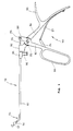
- FIG. 1 to 4 an embodiment of the one with the general Reference numeral 150 provided medical instrument for separating tissue in the human or animal body shown.
- the instrument 150 has an elongate shaft 152, which has a bend 154.
- a movable tool 156 arranged, which is axially movable and with a stationary Tool 158, also at the distal end of the shaft 152 is arranged, cooperates in the manner of a punch.
- a handle 160 At the proximal end of the shaft 152 is a handle 160 with a movable handle portion 162 and a stationary handle portion 164 arranged.
- the movable grip part 162 has a ring 166, through the one, two or three fingers of a hand to operate the movable handle part 162 are pushed through.
- the immovable handle portion 164 has a proximally projecting Extension 168, on which when gripping the handle 160 supports the depression between thumb and forefinger.
- the movable handle portion 162 and the immovable handle portion 164 are hinged together via a hinge 170.
- a leaf spring 172 attached to the immovable handle portion 164 is connected to a lever 174 which is connected to the movable Handle part 162 is articulated.
- the leaf spring 172 in conjunction with the lever 174 biases the movable one Handle part 164 in its illustrated in Fig. 1 open position before, in which the movable handle portion 162 of the immovable Handle part 164 is maximally spaced.
- the movable tool 156 is connected to the movable handle part 162 frictionally connected by a power transmission element 176, which extends through the shaft 152 therethrough.
- the power transmission element 176 At the outermost proximal end, the power transmission element 176 a transversely to the longitudinal direction of the force transmission element 176 extending pin 178, which in a fork section 180 of the movable grip member 162 engages, whereby the power transmission element 176 frictionally with the movable Handle part 162 is connected.
- the power transmission element 176 is characterized by a with the immovable handle part 164 firmly connected pipe section 182 performed on which the shaft 152 via another pipe section 184 is fixed immovably.
- a port 186 for connecting a Arranged not shown purge line, so that the connection 186 a rinsing liquid introduced into the shaft 152 can be moved through the shaft 152 to its distal At the end, they are directed to the operational area exit.
- the power transmission element is shown in FIG. 3 in the range between the movable handle portion 162 and the bend 154 as Rod 188 formed.
- the rod 188 is round in cross-section and lies on the shaft 152 and is in this at its axial Float passed.
- the flat band 190 may be in the form of, for example a leaf spring may be formed from a spring steel.
- the flat band is oriented so that the surface normal its broad flat side in the plane of curvature of the bend 154 is located, the flat broad sides of the tape 190 so in Extend direction transverse to the plane of curvature.
- the flat belt 190 is the power transmission element 176 in the area of the bend in the plane of curvature of the bend 154 flexible and thus can follow the course of the bend 154 always adapt.
- a proximal end 192 of the band 190 is materially bonded connected to the rod 188 of the power transmission element 176, for example by laser welding.
- the flat band 190 from the rod 188 made of solid material by a material-removing process to form, thereby an integral connection of the flat band 190 with the rod 188 is reached.
- a distal end 194 of the flat band 190 is materially bonded connected to the movable tool 156, whereby the non-positive Connection of the power transmission element 176 with the movable tool 156 is produced.
- the movable tool 156 sits axially displaceable on the immovable tool 158, the purpose of a tubular extension 196, on which a sleeve portion 198 of the movable Tool 156 is arranged in the sliding seat.
- the tubular extension 196 of the stationary tool 158 is in turn fixed to the distal end of the shaft 152, For example, by welding, connected.
- a laterally continuous slot 200 present, in which the flat band 190 received axially displaceable is.
- the shaft 152 In the region of the bend 154, the shaft 152 has two in the Shaft wall trained guides 202 and 204 in the form of Slots that pass through the shaft wall 152, so that the shaft 152 in the region of the guides 202 and 204 is open.
- the flat band 190 extends transversely to the longitudinal direction of the Shaft 152 not only about the inside diameter, but also to over the entire outer diameter of the shaft 152, so that its narrow sides in the guides 202 and 204 engage, thereby the flat band 190 in the guides 202 and 204 along the bend 154 of the shaft 152 is guided.
Landscapes
- Health & Medical Sciences (AREA)
- Surgery (AREA)
- Life Sciences & Earth Sciences (AREA)
- Biomedical Technology (AREA)
- Medical Informatics (AREA)
- Orthopedic Medicine & Surgery (AREA)
- Oral & Maxillofacial Surgery (AREA)
- Engineering & Computer Science (AREA)
- Dentistry (AREA)
- Heart & Thoracic Surgery (AREA)
- Nuclear Medicine, Radiotherapy & Molecular Imaging (AREA)
- Molecular Biology (AREA)
- Animal Behavior & Ethology (AREA)
- General Health & Medical Sciences (AREA)
- Public Health (AREA)
- Veterinary Medicine (AREA)
- Surgical Instruments (AREA)
Abstract
Description
- Fig. 1
- ein Ausführungsbeispiel eines erfindungsgemäßen medizinischen Instruments in einer Gesamtdarstellung in Seitenansicht;
- Fig. 2
- das distale Ende des Instruments in Fig. 1 in Seitenansicht und vergrößertem Maßstab;
- Fig. 3
- eine der Fig. 2 entsprechende Darstellung im Längsschnitt; und
- Fig. 4
- einen Schnitt entlang der Linie IV-IV in Fig. 3.
Claims (10)
- Medizinisches Instrument zum Präparieren von Gewebe im menschlichen oder tierischen Körper, mit einem Schaft (152), mit zumindest einem beweglichen Werkzeug (156) an einem distalen Ende des Schafts (152), mit zumindest einem beweglichen Griffteil (162) an einem proximalen Ende des Schafts (152), und mit einem sich längs des Schafts (152) erstreckenden, relativ zu diesem beweglichen auf Schub und/oder Zug arbeitenden Kraftübertragungselement (176), dessen proximales Ende mit dem zumindest einen beweglichen Griffteil (162) und dessen distales Ende mit dem zumindest einen beweglichen Werkzeug (156) kraftschlüssig verbunden ist, wobei der Schaft (152) an zumindest einer Stelle zwischen dem distalen Ende und dem proximalen Ende eine Biegung (154) aufweist, wobei das Kraftübertragungselement (176) zumindest im Bereich der Biegung (154) quer zu einer Krümmungsebene der Biegung (154) axial durchgehend als flaches biegeelastisches Band ausgebildet ist, das sich im Bereich der Biegung (154) in Richtung quer zur Krümmungsebene axial durchgehend zumindest über den Innendurchmesser des Schafts (152) erstreckt, dadurch gekennzeichnet, dass das flache Band (190) mit seinen Schmalseiten in seitlichen Führungen (202) des Schafts (152) geführt ist.
- Instrument nach Anspruch 1, dadurch gekennzeichnet, dass die Führungen (202) als Nuten in einer Innenwand des Schafts (152) ausgebildet sind.
- Instrument nach Anspruch 1, dadurch gekennzeichnet, dass die Führungen (202) als offene Schlitze (200) in dem Schaft (152) ausgebildet sind.
- Instrument nach einem der Ansprüche 1 bis 3, dadurch gekennzeichnet, dass das Kraftübertragungselement (176) in Bereichen außerhalb der Biegung (154) als massiver Stab (188) aus einem Vollmaterial ausgebildet ist.
- Instrument nach Anspruch 4, dadurch gekennzeichnet, dass das flache Band (190) in einem materialabtragenden Verfahren aus dem Stab (188) aus Vollmaterial gebildet ist.
- Instrument nach Anspruch 4, dadurch gekennzeichnet, dass das Band (190) stoffschlüssig mit dem Stab (188) verbunden ist.
- Instrument nach einem der Ansprüche 1 bis 6, dadurch gekennzeichnet, dass das zumindest eine bewegliche Werkzeug (156) relativ zum Schaft (152) axial beweglich ist, wobei ein zweites Werkzeug (158) am distalen Ende des Schafts (152) angeordnet ist, wobei das bewegliche Werkzeug (156) und das zweite Werkzeug (158) durch axiale Relativbewegung zueinander in Form einer Stanze zusammenwirken.
- Instrument nach Anspruch 7, dadurch gekennzeichnet, dass das zweite Werkzeug (158) unbeweglich mit dem Schaft (152) verbunden ist und distal vor dem beweglichen Werkzeug (156) angeordnet ist.
- Instrument nach Anspruch 7 oder 8, dadurch gekennzeichnet, dass das bewegliche Werkzeug (156) relativ zum zweiten Werkzeug (158) verdrehgesichert ist.
- Instrument nach einem der Ansprüche 1 bis 9, dadurch gekennzeichnet, dass das zumindest eine bewegliche Werkzeug als um ein Drehgelenk verschwenkbares Maulteil ausgebildet ist, das mit einem zweiten Werkzeug in der Art einer Schere oder Zange zusammenwirkt.
Priority Applications (1)
| Application Number | Priority Date | Filing Date | Title |
|---|---|---|---|
| EP05012958A EP1582157B1 (de) | 1999-04-29 | 2000-04-14 | Medizinisches Instrument zum Präparieren von Gewebe |
Applications Claiming Priority (4)
| Application Number | Priority Date | Filing Date | Title |
|---|---|---|---|
| EP99108380 | 1999-04-29 | ||
| EP99108380A EP1055397B1 (de) | 1999-04-29 | 1999-04-29 | Medizinisches Instrument zum Präparieren von Gewebe |
| EP05012958A EP1582157B1 (de) | 1999-04-29 | 2000-04-14 | Medizinisches Instrument zum Präparieren von Gewebe |
| EP20000107946 EP1050275B1 (de) | 1999-04-29 | 2000-04-14 | Medizinisches Instrument zum Präparieren von Gewebe |
Related Parent Applications (1)
| Application Number | Title | Priority Date | Filing Date |
|---|---|---|---|
| EP20000107946 Division EP1050275B1 (de) | 1999-04-29 | 2000-04-14 | Medizinisches Instrument zum Präparieren von Gewebe |
Publications (2)
| Publication Number | Publication Date |
|---|---|
| EP1582157A1 true EP1582157A1 (de) | 2005-10-05 |
| EP1582157B1 EP1582157B1 (de) | 2007-10-03 |
Family
ID=26070807
Family Applications (2)
| Application Number | Title | Priority Date | Filing Date |
|---|---|---|---|
| EP20000107946 Expired - Lifetime EP1050275B1 (de) | 1999-04-29 | 2000-04-14 | Medizinisches Instrument zum Präparieren von Gewebe |
| EP05012958A Expired - Lifetime EP1582157B1 (de) | 1999-04-29 | 2000-04-14 | Medizinisches Instrument zum Präparieren von Gewebe |
Family Applications Before (1)
| Application Number | Title | Priority Date | Filing Date |
|---|---|---|---|
| EP20000107946 Expired - Lifetime EP1050275B1 (de) | 1999-04-29 | 2000-04-14 | Medizinisches Instrument zum Präparieren von Gewebe |
Country Status (1)
| Country | Link |
|---|---|
| EP (2) | EP1050275B1 (de) |
Families Citing this family (2)
| Publication number | Priority date | Publication date | Assignee | Title |
|---|---|---|---|---|
| DE102014012146A1 (de) * | 2014-08-14 | 2016-02-18 | Bacher Medizintechnik GmbH | Rohrschaftinstrument mit einem Rohrschaft und einem Spülanschluss |
| WO2023102897A1 (zh) * | 2021-12-10 | 2023-06-15 | 美科特医疗科技(苏州)有限公司 | 一种柔性连接件及末端执行器组件 |
Citations (6)
| Publication number | Priority date | Publication date | Assignee | Title |
|---|---|---|---|---|
| US4646745A (en) | 1981-09-03 | 1987-03-03 | United States Surgical Corporation | Surgical stapler apparatus with curved shaft |
| DE8712835U1 (de) * | 1987-09-23 | 1987-11-19 | Weba Medizinmechanik GmbH u. Co, 7208 Spaichingen | Chirurgisches Instrument |
| DE4300064A1 (de) | 1993-01-05 | 1994-07-07 | Wolf Gmbh Richard | Gewebestanze |
| US5507772A (en) | 1993-05-25 | 1996-04-16 | Depuy Inc. | Cleanable, inspectable, and replaceable surgical instrument |
| DE4444025A1 (de) | 1994-12-10 | 1996-06-20 | Storz Karl Gmbh & Co | Betätigungselement für medizinische Zangen |
| DE19520717A1 (de) * | 1995-06-12 | 1996-12-19 | Aesculap Ag | Chirurgisches Rohrschaftinstrument |
-
2000
- 2000-04-14 EP EP20000107946 patent/EP1050275B1/de not_active Expired - Lifetime
- 2000-04-14 EP EP05012958A patent/EP1582157B1/de not_active Expired - Lifetime
Patent Citations (7)
| Publication number | Priority date | Publication date | Assignee | Title |
|---|---|---|---|---|
| US4646745A (en) | 1981-09-03 | 1987-03-03 | United States Surgical Corporation | Surgical stapler apparatus with curved shaft |
| DE8712835U1 (de) * | 1987-09-23 | 1987-11-19 | Weba Medizinmechanik GmbH u. Co, 7208 Spaichingen | Chirurgisches Instrument |
| DE4300064A1 (de) | 1993-01-05 | 1994-07-07 | Wolf Gmbh Richard | Gewebestanze |
| US5507772A (en) | 1993-05-25 | 1996-04-16 | Depuy Inc. | Cleanable, inspectable, and replaceable surgical instrument |
| DE4444025A1 (de) | 1994-12-10 | 1996-06-20 | Storz Karl Gmbh & Co | Betätigungselement für medizinische Zangen |
| DE19520717A1 (de) * | 1995-06-12 | 1996-12-19 | Aesculap Ag | Chirurgisches Rohrschaftinstrument |
| DE19520717C2 (de) | 1995-06-12 | 1998-09-24 | Aesculap Ag & Co Kg | Chirurgisches Rohrschaftinstrument |
Also Published As
| Publication number | Publication date |
|---|---|
| EP1582157B1 (de) | 2007-10-03 |
| EP1050275A1 (de) | 2000-11-08 |
| EP1050275B1 (de) | 2005-09-21 |
Similar Documents
| Publication | Publication Date | Title |
|---|---|---|
| EP1055397B1 (de) | Medizinisches Instrument zum Präparieren von Gewebe | |
| EP0594946B1 (de) | Greif- und/oder Schneidinstrument für endoskopische Zwecke | |
| DE69218688T2 (de) | Zange | |
| EP0892620B1 (de) | Chirurgischer fadenschneider | |
| DE3126578C2 (de) | Zweischenkliges Nahtherstellungsinstrument zur Verwendung in der Chirurgie | |
| EP2612609B1 (de) | Medizinisches Instrument | |
| EP1052945B1 (de) | Medizinisches rohrschaftinstrument | |
| DE4204051C2 (de) | Amboßschere für chirurgische Zwecke | |
| DE29616210U1 (de) | Handhabe für chirurgische Instrumente | |
| EP0412282A1 (de) | Endoskop für die nasale Chirurgie | |
| DE3741879A1 (de) | Endoskopisches instrument | |
| DE4323809A1 (de) | Endoskopieschere | |
| DE8535164U1 (de) | Chirurgisches Greifinstrument | |
| DE102008028992B3 (de) | Chirurgische Zange mit Messer und Rückstellfeder | |
| EP1488749B1 (de) | Medizinisches Instrument | |
| DE102010033424B4 (de) | Endoskopisches Instrument | |
| EP1629785B1 (de) | Medizinische Zange | |
| EP1582157B1 (de) | Medizinisches Instrument zum Präparieren von Gewebe | |
| EP3155973B1 (de) | Biopsiezange | |
| DE19633811A1 (de) | Chirurgisches Instrument | |
| DE102015120725A1 (de) | Medizinisches Schneidinstrument | |
| EP4311510B1 (de) | Medizinisches schlaginstrument | |
| DE10159584A1 (de) | Verbiegbares Endoskopinstrument | |
| DE4336634C2 (de) | Mikroinstrument für mikrochirurgische Eingriffe | |
| DE69304601T2 (de) | Kupplungseinrichtung für chirurgische Instrumente |
Legal Events
| Date | Code | Title | Description |
|---|---|---|---|
| PUAI | Public reference made under article 153(3) epc to a published international application that has entered the european phase |
Free format text: ORIGINAL CODE: 0009012 |
|
| AC | Divisional application: reference to earlier application |
Ref document number: 1050275 Country of ref document: EP Kind code of ref document: P |
|
| AK | Designated contracting states |
Kind code of ref document: A1 Designated state(s): DE FR GB IT |
|
| 17P | Request for examination filed |
Effective date: 20060303 |
|
| AKX | Designation fees paid |
Designated state(s): DE FR GB IT |
|
| GRAP | Despatch of communication of intention to grant a patent |
Free format text: ORIGINAL CODE: EPIDOSNIGR1 |
|
| GRAS | Grant fee paid |
Free format text: ORIGINAL CODE: EPIDOSNIGR3 |
|
| GRAA | (expected) grant |
Free format text: ORIGINAL CODE: 0009210 |
|
| AC | Divisional application: reference to earlier application |
Ref document number: 1050275 Country of ref document: EP Kind code of ref document: P |
|
| AK | Designated contracting states |
Kind code of ref document: B1 Designated state(s): DE FR GB IT |
|
| REG | Reference to a national code |
Ref country code: GB Ref legal event code: FG4D Free format text: NOT ENGLISH |
|
| REF | Corresponds to: |
Ref document number: 50014699 Country of ref document: DE Date of ref document: 20071115 Kind code of ref document: P |
|
| ET | Fr: translation filed | ||
| GBT | Gb: translation of ep patent filed (gb section 77(6)(a)/1977) |
Effective date: 20080402 |
|
| PLBE | No opposition filed within time limit |
Free format text: ORIGINAL CODE: 0009261 |
|
| STAA | Information on the status of an ep patent application or granted ep patent |
Free format text: STATUS: NO OPPOSITION FILED WITHIN TIME LIMIT |
|
| 26N | No opposition filed |
Effective date: 20080704 |
|
| REG | Reference to a national code |
Ref country code: FR Ref legal event code: PLFP Year of fee payment: 16 |
|
| PGFP | Annual fee paid to national office [announced via postgrant information from national office to epo] |
Ref country code: GB Payment date: 20150324 Year of fee payment: 16 Ref country code: FR Payment date: 20150319 Year of fee payment: 16 |
|
| PGFP | Annual fee paid to national office [announced via postgrant information from national office to epo] |
Ref country code: IT Payment date: 20150330 Year of fee payment: 16 |
|
| GBPC | Gb: european patent ceased through non-payment of renewal fee |
Effective date: 20160414 |
|
| REG | Reference to a national code |
Ref country code: FR Ref legal event code: ST Effective date: 20161230 |
|
| PG25 | Lapsed in a contracting state [announced via postgrant information from national office to epo] |
Ref country code: FR Free format text: LAPSE BECAUSE OF NON-PAYMENT OF DUE FEES Effective date: 20160502 Ref country code: GB Free format text: LAPSE BECAUSE OF NON-PAYMENT OF DUE FEES Effective date: 20160414 |
|
| PG25 | Lapsed in a contracting state [announced via postgrant information from national office to epo] |
Ref country code: IT Free format text: LAPSE BECAUSE OF NON-PAYMENT OF DUE FEES Effective date: 20160414 |
|
| PGFP | Annual fee paid to national office [announced via postgrant information from national office to epo] |
Ref country code: DE Payment date: 20170321 Year of fee payment: 18 |
|
| REG | Reference to a national code |
Ref country code: DE Ref legal event code: R082 Ref document number: 50014699 Country of ref document: DE Representative=s name: WITTE, WELLER & PARTNER PATENTANWAELTE MBB, DE Ref country code: DE Ref legal event code: R081 Ref document number: 50014699 Country of ref document: DE Owner name: KARL STORZ SE & CO. KG, DE Free format text: FORMER OWNER: KARL STORZ GMBH & CO. KG, 78532 TUTTLINGEN, DE |
|
| REG | Reference to a national code |
Ref country code: DE Ref legal event code: R119 Ref document number: 50014699 Country of ref document: DE |
|
| PG25 | Lapsed in a contracting state [announced via postgrant information from national office to epo] |
Ref country code: DE Free format text: LAPSE BECAUSE OF NON-PAYMENT OF DUE FEES Effective date: 20181101 |