EP1580913A2 - Optischer Schalter und Netzwerksystem unter Verwendung desselben - Google Patents
Optischer Schalter und Netzwerksystem unter Verwendung desselben Download PDFInfo
- Publication number
- EP1580913A2 EP1580913A2 EP04021918A EP04021918A EP1580913A2 EP 1580913 A2 EP1580913 A2 EP 1580913A2 EP 04021918 A EP04021918 A EP 04021918A EP 04021918 A EP04021918 A EP 04021918A EP 1580913 A2 EP1580913 A2 EP 1580913A2
- Authority
- EP
- European Patent Office
- Prior art keywords
- optical
- switch
- regard
- information
- optical signal
- Prior art date
- Legal status (The legal status is an assumption and is not a legal conclusion. Google has not performed a legal analysis and makes no representation as to the accuracy of the status listed.)
- Withdrawn
Links
Images


Classifications
-
- H—ELECTRICITY
- H04—ELECTRIC COMMUNICATION TECHNIQUE
- H04J—MULTIPLEX COMMUNICATION
- H04J14/00—Optical multiplex systems
- H04J14/02—Wavelength-division multiplex systems
- H04J14/0227—Operation, administration, maintenance or provisioning [OAMP] of WDM networks, e.g. media access, routing or wavelength allocation
-
- H—ELECTRICITY
- H04—ELECTRIC COMMUNICATION TECHNIQUE
- H04J—MULTIPLEX COMMUNICATION
- H04J14/00—Optical multiplex systems
- H04J14/02—Wavelength-division multiplex systems
- H04J14/0221—Power control, e.g. to keep the total optical power constant
-
- H—ELECTRICITY
- H04—ELECTRIC COMMUNICATION TECHNIQUE
- H04J—MULTIPLEX COMMUNICATION
- H04J14/00—Optical multiplex systems
- H04J14/02—Wavelength-division multiplex systems
- H04J14/0227—Operation, administration, maintenance or provisioning [OAMP] of WDM networks, e.g. media access, routing or wavelength allocation
- H04J14/0254—Optical medium access
- H04J14/0267—Optical signaling or routing
- H04J14/0269—Optical signaling or routing using tables for routing
-
- H—ELECTRICITY
- H04—ELECTRIC COMMUNICATION TECHNIQUE
- H04L—TRANSMISSION OF DIGITAL INFORMATION, e.g. TELEGRAPHIC COMMUNICATION
- H04L45/00—Routing or path finding of packets in data switching networks
- H04L45/12—Shortest path evaluation
-
- H—ELECTRICITY
- H04—ELECTRIC COMMUNICATION TECHNIQUE
- H04L—TRANSMISSION OF DIGITAL INFORMATION, e.g. TELEGRAPHIC COMMUNICATION
- H04L45/00—Routing or path finding of packets in data switching networks
- H04L45/48—Routing tree calculation
-
- H—ELECTRICITY
- H04—ELECTRIC COMMUNICATION TECHNIQUE
- H04L—TRANSMISSION OF DIGITAL INFORMATION, e.g. TELEGRAPHIC COMMUNICATION
- H04L45/00—Routing or path finding of packets in data switching networks
- H04L45/62—Wavelength based
-
- H—ELECTRICITY
- H04—ELECTRIC COMMUNICATION TECHNIQUE
- H04Q—SELECTING
- H04Q11/00—Selecting arrangements for multiplex systems
- H04Q11/0001—Selecting arrangements for multiplex systems using optical switching
- H04Q11/0062—Network aspects
-
- H—ELECTRICITY
- H04—ELECTRIC COMMUNICATION TECHNIQUE
- H04J—MULTIPLEX COMMUNICATION
- H04J14/00—Optical multiplex systems
- H04J14/02—Wavelength-division multiplex systems
- H04J14/0278—WDM optical network architectures
- H04J14/0284—WDM mesh architectures
-
- H—ELECTRICITY
- H04—ELECTRIC COMMUNICATION TECHNIQUE
- H04Q—SELECTING
- H04Q11/00—Selecting arrangements for multiplex systems
- H04Q11/0001—Selecting arrangements for multiplex systems using optical switching
- H04Q11/0062—Network aspects
- H04Q2011/0073—Provisions for forwarding or routing, e.g. lookup tables
Definitions
- the present invention relates to an optical switch for switching optical signals and a network systemprovided with the optical switch.
- Ethernet which works on layer two (including Fast Ethernet, Gigabit Ethernet, and 10 Gigabit Ethernet) has been used in a local area network (LAN).
- LAN local area network
- application area of layer-2 Ethernet expands to a metro area network (MAN) and a wide area network (WAN) as well as LAN, as can be seen wide area Ethernet services becoming popular.
- WAN wide area network
- SAN storage area network
- optical interface such as fiber channel for use in Gigabit Ethernet, 10 Gigabit Ethernet and SAN has been standardized.
- it is highlyprobable that a network using an optical switch becomes popular by use of ultra high-speed interface of 10 Gigabit Ethernet class, in which optical signals are being switched in the form of light.
- STP spanning tree protocol
- STP is a method of configuring a tree structure in a switching network working on layer 2, extending to the entire switches in the network while only one route is existent for each of the entire destinations. With this, while a redundant route is secured even in the event of a failure, logical wiring can be determined avoiding network stoppage caused by a packet loop.
- a switch located at the center of the tree is termed root bridge.
- a switch having a minimum bridge ID (identification number) value is selected.
- a root path cost against the root bridge is calculated.
- a route having the minimum root path cost is set to a forwarding state (a state transmitting data frames) ; and other routes having greater root path costs than the above is set to a blocking state (a state suspending transmission of data frames).
- the path cost of a link between each switch is obtained from the link transmission speed.
- a port in each switch is shifted from a blocking state, through a listening state and a learning state, to a forwarding state. The above each state will be explained in the following FIG. 1.
- FIG. 1 shows a diagram illustrating state transitions in each port of a switch.
- Each port can take the blocking state, the listening state, the learning state, the forwarding state, and further a disable state.
- the blocking state data traffic is neither transmitted nor received. Namely, data traffic is discarded, and only BPDU (bridge protocol data unit) is received.
- BPDU bridge protocol data unit
- the listening state data traffic is neither transmitted nor received, and the incoming data traffic is discarded, while BPDU is transmitted and received to form an STP tree topology.
- the learning state data traffic is neither transmitted nor received, and the incoming data traffic is discarded. Learning MAC address and generating an MAC address table are performed in this state.
- each MAC address provided in the equipment connected to each switch port is retained in this table, correspondingly to each port.
- the disable state is a state other than the above four states, that is, each port stays ineffective or STP is inoperable. Transitions between each state are performed based on each condition corresponding to reference numbers (1), (2), (3), (4) and (5) attached to each arrow shown in FIG. 1.
- the reference number (1) denotes a case that the port becomes either effective or initialized
- the reference number (2) denotes a case of the port becoming ineffective
- the reference number (3) denotes a case of the port being selected as designated port or root port
- the reference number (4) is a case of the port being selected as blocking port
- the reference number (5) is a case when a predetermined time (forward delay: time for shifting to the learning state or the forwarding state) has elapsed.
- FIGS. 2A, 2B show diagrams illustrating an exemplary STP tree topology configuration.
- logical topology shown in FIG. 2B is structured by exchanging BPDU to determine a route. The procedure for structuring this topology is explained below.
- a switch having the minimum value of bridge ID (a 64-bit numeral 1 constituted of 16-bit ⁇ priority' combined with 48-bit MAC address of each switch) is selected as root bridge.
- a root port which is a port positioned nearest to the root bridge, is selected.
- the switch adds the path cost of the port that has received the BPDU, and transfers the new BPDU further to the downstream switches.
- each switch receives a plurality of BPDU.
- the port having received the BPDU including the least root path cost value is selected as root port.
- All ports in the root bridge are selected as designated ports without exception. Further, among the ports in each segment (where a segment is a link between switches), a port having a shortest route to the root bridge is selected as designated port.
- the ports having been selected as root port and designated port are set as forwarding ports.
- the ports having been selected neither root port nor designated port are set as blocking ports.
- logical topology having a tree structure ( i . e . tree topology) by STP is structured in regard to the network constituted of electric switches.
- an optical switch capable of switching the routes in the form of light without performing opto-electric conversion is a key technology for optical networks.
- the optical switch has such features as being free from protocols (Ethernet or Fiber Channel) , and capable of passing signals at arbitrary bit rates. Because of these features, the optical switch is considered as a switch having dominant possibility for use in the future network.
- exchanging BPDU control frames employed in STP has not been taken into account, and therefore it is difficult to implement the STP function. As a result, in a network constituted of a plurality of optical switches, an unintended packet loop may possibly be produced.
- an object of the present invention to provide an optical switch capable of automatic configuration of transmission routes of a tree structure, and a network system constituted of the above optical switch.
- a first optical switch having a plurality of ports and being capable of switching optical signal routes in the form of light.
- the first optical switch includes: a detection means detecting information in regard to a transmission condition of an optical signal passing through each port; and a control means exchanging the above-mentioned information in regard to the transmission condition between each switch, and controlling each port so that a single route is selected from among the plurality of routes on which optical signals are transmitted, based on the difference of the information in regard to the transmission condition between each switch.
- the information in regard to the transmission condition is optical signal power.
- a transmission route either having a minimum difference of the information between each switch, or when at least one switch intervenes in the middle of the transmission route, having a minimum accumulation of the differences between each switch, is selected.
- a second optical switch which includes a detection means detecting information in regard to a transmission condition of an optical signal input into each port; and a control means controlling each port so that a single route is selected from among the plurality of routes on which the optical signals are transmitted, based on the above-mentioned information in regard to the transmission condition of the optical signal detected in each port.
- the information in regard to the transmission condition is optical signal power, and a transmission route through which an optical signal is input into a port having received the maximum optical signal power is selected.
- control means transmits and receives the information in regard to the transmission condition between each switch, using an extended BPDU format having an additional information field in regard to the transmission condition, which is added to the bridge protocol data unit (BPDU) format of the spanning tree protocol (STP).
- BPDU bridge protocol data unit
- STP spanning tree protocol
- control means transmits and receives the information in regard to the transmission condition via a signal line network different from the network constituting the optical signal transmission routes.
- the tree structure is configured using STP.
- the conventional optical switch it is not possible to read the signal contents because switching is carried out in the form of light. Therefore, it is not possible to configure the tree structure.
- a method for configuring the tree structure in an optical network by the use of light power (intensity) information This enables automatic setting of the tree structure in the optical network system, which has been performed through manual operation in the conventional method, and reduction in terms of time and human costs can be achieved. Further, in the event of a failure, failure detection can be attained earlier by monitoring the light power, and as a result, switchover to a redundant route can be achieved faster than in the case when the electric switches are used.
- optical signal power (light intensity) is monitored, and an optical path cost is calculated based on optical power loss, without converting an optical signal transmitting between each optical switch to an electric signal.
- optical path cost Based on the calculated optical path cost, logical topology of a tree structure using optical switches is constructed.
- FIG. 3 shows an exemplary network configuration (physical topology) constituted of a plurality of optical switches according to the embodiment of the present invention.
- the network shown in FIG. 3 is constituted of four optical switches OSWa (optical bridge ID: 1), OSWb (optical bridge ID: 2), OSWc (optical bridge ID: 3), and OSWd (optical bridge ID: 4) .
- optical switch OSWa has ports a1, a2
- optical switch OSWb has ports b1, b2
- optical switch OSWc has ports c1, c2
- optical switch OSWd has ports d1, d2, respectively.
- Optical switches OSWa and OSWb are connected by an optical link L4 having an assumed path cost (optical link path cost) of, for example, 6 (dB) .
- the optical link path cost is a difference of the power loss in the optical link concerned.
- OSWa and OSWc are connected by an optical link L1 having an assumed link loss of 3 (dB)
- OSWc and OSWd are connected by an optical link L2 having an assumed link loss of 4 (dB)
- OSWb and OSWd are connected by an optical link L3 having an assumed link loss of 3 (dB)
- OSWc and OSWb are connected by an optical link L5 having an assumed optical link path cost of 4 (dB) .
- each link is constituted of an upward channel and a downward channel.
- Each link loss shown in FIG. 3 is, for example, an average optical link loss on the upward channel and the downward channel.
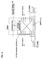
- FIG. 4 shows a diagram illustrating an internal configuration of an optical switch according to the embodiment of the present invention.
- OSWa includes a switch 14 that enables switching of a plurality of input ports 12 and a plurality of output ports 13.
- OSWa includes: an optical branch section 15 by which a portion of optical signals is made to branch at least from either one of input port 12 and output port 13 (branching from the input port is illustrated in the example shown in FIG.
- an optical receiver 16 which receives the optical signal having been made to branch, and measures the light power thereof; and a controller 17 which controls port connection based on the light power measured by optical receiver 16 and the light power information acquired from other switches, and determines an optical signal route. Controller 17 acquires optical signal power information measured in other switches, calculates each path cost of the optical link (optical link path cost) between the switches, and performs port switching control.
- a paired combination of an input port and an output port shown in FIG. 4 corresponds to each single port shown in FIG. 3.
- optical link path cost In order to configure network tree topology constituted of optical switches, the following are specified in addition to the above-mentioned optical link path cost, and an optical switch path cost.
- tree topology of the optical switches is configured by the following procedure.
- optical switch of which optical bridge ID is the smallest value is selected as optical root bridge.
- optical root path costs of the ports in the optical switch concerned are obtained.
- the port having the least optical root path cost is set as root port.
- the entire ports of the optical root bridge are determined as optical designated ports. Also, among the ports connected to each optical link, the ports having small optical root path costs are determined as optical designated ports.
- optical root port and the entire ports selected as optical designated port are set as optical forwarding ports.
- a tree topology in the network constituted of optical switches can be configured. Namely, the tree topology throughout the entire network can be configured autonomously using the above-mentioned procedure performed by each optical switch.
- a control plane is prepared to transmit optical path costs obtained from light power.
- the control plane is a network constituted of signal lines physically different from the data plane.
- power information of the optical signals on the data plane (light power information) is transmitted in the form of electric signals.
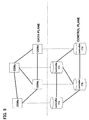
- FIG. 5 shows a conceptual diagram of the data plane and the control plane.
- a control plane network is provided corresponding to the data plane network transmitting optical signals through each optical switch OSWa, OSWb, OSWc, OSWd.
- each controller 17a, 17b, 17c, 17d (here, suffixes a, b, c, d are added to identify each controller 17 in the switches) of each optical switch OSWa, OSWb, OSWc, OSWd stores light power information on the control plane, and also exchanges light power information with other optical switches.
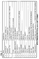
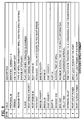
- FIG. 6 shows a diagram illustrating exemplary control information stored and transmitted on the control plane.
- each controller 17 in the switch has a table (table A, table B, table C, tableD) stored in a predetermined memory area, having input power and output power (both upward signal power and downward signal power) , and optical link path cost as well, corresponding to each port.
- Each controller 17a, 17b, 17c, 17d in each optical switch OSWa, OSWb, OSWc, OSWd exchanges control information stored in each table using extended BPDU, which is an extended format of BPDU used in STP for electric switches, and will be explained later.
- extended BPDU which is an extended format of BPDU used in STP for electric switches, and will be explained later.
- exemplary control information (light power information) to be exchanged between the switches is shown with respect to both an upward signal and a downward signal.
- FIG. 7 shows a diagram illustrating the BPDU format in STP for electric switches.
- BPDU messages type: '00000000'b
- TCN topology change notification
- a new message type is added for this purpose.
- the name of this new message type is, for example, optical configuration BPDU (message type: other than the values '10000000'b and '00000000'b, for example, '00001000'b).
- BPDU optical configuration BPDU
- FIG. 8 shows exemplary fields newly added to the BPDU format. As shown in FIG. 8, two fields are added: one is "port input power" which denotes an optical signal power value input to the port, and the other is “port output power” which denotes an optical signal power value output from the port.
- FIG. 9 shows an exemplary configuration of an extended BPDU format according to the embodiment of the present invention.
- the fields shown in FIG. 8 are added to the BPDU format shown in FIG. 7.
- Each optical switches measures light power values on each input/output port, The measured values are inserted into the field values of "port input power” and “port output power”, respectively, and transmitted to other optical switches. Calculation of optical link path cost is performed following transmission and reception of these values.
- each optical switch sets the message type value of the extended BPDU format to '00001000'b, and transmits the extended BPDU frame to other optical switches.
- a port a1 of the switch OSWa and a port b1 of the switch OSWb are considered in the following description.
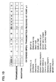
- FIG. 10 shows exemplary frames transmitted and received on the port a1
- FIG. 11 shows exemplary frames transmitted and received on the port b1.
- the optical link path cost of the link on the transmission side is 6 dB
- the optical link path cost of the link on the reception side is also 6 dB.
- the optical link path cost of this link L4 becomes 6 dB.
- the switch OSWb also, the similar calculation is performed, and the result is: the optical link path cost on the transmission side is 6 dB, and the optical link path cost on the reception side is 6 dB. From the above results, both the optical transmission/reception power and the optical link path cost value of each transmission/reception port are stored in the switch OSWa and the switch OSWb, respectively. In a similar manner, light power information is exchanged among the entire switches in the network. Thus, a loss in the link connected to each port, namely the optical link path cost, is retained in each switch (refer to table A, table B, table C, table D).
- the optical switch of which optical link path cost of each port has been determined, sets a message type value of the extended BPDU to the value ('00000000'b) for declaring a configuration BPDU, and performs the aforementioned processing (1) to (5).
- logical topology in the optical switch network can be configured.
- a tree structure is configured, in which a transmission route for an optical signal is uniquely determined.
- optical switch path cost an optical signal loss (which is termed optical switch path cost) produced inside each optical switch into consideration, in addition to the optical link path cost.
- the optical switch itself is also a portion of the optical signal transmission line, and the loss produced while the optical signal is input to the optical switch and output therefrom depends on each switch. Therefore, determining optical signal transmission route in consideration of optical switch path cost, in addition to the optical link path cost, enables more accurate route decision, and configuration of more preferable tree structure as well.
- the root bridge outputs optical signals using the entire transmission routes connecting between the root bridge and an object switch for route selection (route selection object switch) .
- the route selection object switch determines the port having received the highest light power as root port.
- the light power received on the port of interest is compared with the light power received on the port of other switches being connected to the port of interest via an optical link.
- the port having higher light power is determined as designated port.
- the ports other than those having been set as root port and designated port are set as blocking ports.
- the tree structure can be configured.
- a route switchover of an optical signal transmitted from the optical root bridge and an information exchange of light power measured by an optical switch other than the optical root bridge are performed through exchanging the signal on the control plane by use of the aforementioned extended BPDU.
- the tree topology is configured by calculating the path cost based on the light power.
- an optical signal-to-noise ratio (OSNR) can be measured in the optical switch.
- OSNR optical signal-to-noise ratio
- OSNR is an important value to determine the signal quality. From that point of view, it is possible to measure OSNR in the optical switch, and use the measured value as the optical link path cost.
- a signal bit rate As other means for path cost evaluation, it may be possible to use a signal bit rate, a type or length of the optical fiber used as transmission medium, the number of opto-electric and electro-optical converters inserted in the middle of the transmission line, etc. It is also possible to use combination of the above two, or more.
- the embodiment of the present invention may also be applicable when a packet switch having an optical buffer for obtaining the destination of a packet through optical processing is actualized.
- operation using the data plane network only becomes possible, not only the two-stage configuration constituted of the control plane and the data plane having been described above.
- Basic operation thereof is identical to the STP of electric switches.
- BPDU the extended BPDU shown in FIG. 9 is adopted instead of the BPDU for electric switches, so that the optical link path cost values calculated from measured light power values are used as indexes for structuring the tree.
- the optical link path cost values are calculated by exchanging the optical configuration BPDU, which are then stored in each memory area of the switch.
- a tree structure is configured.
- the optical link path cost obtained through exchanging the optical configuration BPDU is used as path cost.
Landscapes
- Engineering & Computer Science (AREA)
- Computer Networks & Wireless Communication (AREA)
- Signal Processing (AREA)
- Small-Scale Networks (AREA)
- Data Exchanges In Wide-Area Networks (AREA)
- Optical Communication System (AREA)
Applications Claiming Priority (2)
| Application Number | Priority Date | Filing Date | Title |
|---|---|---|---|
| JP2004086932A JP4532950B2 (ja) | 2004-03-24 | 2004-03-24 | 光スイッチ及びそれを備えたネットワークシステム |
| JP2004086932 | 2004-03-24 |
Publications (2)
| Publication Number | Publication Date |
|---|---|
| EP1580913A2 true EP1580913A2 (de) | 2005-09-28 |
| EP1580913A3 EP1580913A3 (de) | 2015-01-07 |
Family
ID=34858431
Family Applications (1)
| Application Number | Title | Priority Date | Filing Date |
|---|---|---|---|
| EP04021918.0A Withdrawn EP1580913A3 (de) | 2004-03-24 | 2004-09-15 | Optischer Schalter und Netzwerksystem unter Verwendung desselben |
Country Status (3)
| Country | Link |
|---|---|
| US (1) | US7715709B2 (de) |
| EP (1) | EP1580913A3 (de) |
| JP (1) | JP4532950B2 (de) |
Families Citing this family (12)
| Publication number | Priority date | Publication date | Assignee | Title |
|---|---|---|---|---|
| ITMI20042091A1 (it) * | 2004-11-02 | 2005-02-02 | Marconi Comm Spa | Instradamento di percorsi ottici in una rete con limitate capacita' di rigenerazione-conversione |
| JP4755457B2 (ja) * | 2005-07-15 | 2011-08-24 | 株式会社日立製作所 | 光ネットワーク装置及び光ネットワーク |
| JP4527650B2 (ja) * | 2005-10-31 | 2010-08-18 | 富士通株式会社 | 物理配線制御装置、物理配線制御方法および物理配線制御プログラム |
| US8089904B2 (en) * | 2006-08-01 | 2012-01-03 | Opnet Technologies, Inc. | Link inference in large networks based on incomplete data |
| JP5281119B2 (ja) * | 2011-05-24 | 2013-09-04 | 富士通テレコムネットワークス株式会社 | 光パケット交換システム |
| US8537810B2 (en) * | 2011-06-29 | 2013-09-17 | Telefonaktiebolaget L M Ericsson (Publ) | E-tree using two pseudowires between edge routers with enhanced learning methods and systems |
| US9054828B2 (en) | 2011-10-14 | 2015-06-09 | Glimmerglass Networks, Inc. | Method and system for managing optical distribution network |
| CN104125083A (zh) * | 2013-04-24 | 2014-10-29 | 中兴通讯股份有限公司 | 一种网络设备的主备倒换方法、装置、设备及系统 |
| US20160283828A1 (en) * | 2015-03-27 | 2016-09-29 | Kyocera Document Solutions Inc. | Automated Print Job Redirection |
| US11463325B2 (en) * | 2017-06-28 | 2022-10-04 | Ciena Corporation | Multi-layer optical network management graphical user interface and visualizations |
| TWI670955B (zh) * | 2018-09-20 | 2019-09-01 | 中華電信股份有限公司 | 具有光交換機之高速交換網路系統 |
| US20250175249A1 (en) * | 2023-11-26 | 2025-05-29 | Xieon Networks S.A.R.L. | System and method for providing transient resilient transmissions in an optical network |
Family Cites Families (26)
| Publication number | Priority date | Publication date | Assignee | Title |
|---|---|---|---|---|
| US5940771A (en) * | 1991-05-13 | 1999-08-17 | Norand Corporation | Network supporting roaming, sleeping terminals |
| DE69429983T2 (de) * | 1994-05-25 | 2002-10-17 | International Business Machines Corp., Armonk | Datenübertragungsnetz und Verfahren zum Betreiben des Netzes |
| US6108308A (en) * | 1996-09-17 | 2000-08-22 | International Business Machines Corporation | System and method for dynamic video routing |
| US6256295B1 (en) * | 1997-09-25 | 2001-07-03 | Nortel Networks Limited | Method and apparatus for determining multiple minimally-overlapping paths between nodes in a network |
| US6531114B1 (en) * | 1999-04-06 | 2003-03-11 | Wm. Wrigley Jr. Company | Sildenafil citrate chewing gum formulations and methods of using the same |
| AU7826600A (en) * | 1999-09-03 | 2001-04-10 | Oni Systems Corp. | Optical power management in an optical network |
| JP4147730B2 (ja) * | 2000-07-12 | 2008-09-10 | 沖電気工業株式会社 | 波長多重伝送システム |
| US6704301B2 (en) * | 2000-12-29 | 2004-03-09 | Tropos Networks, Inc. | Method and apparatus to provide a routing protocol for wireless devices |
| JP4433625B2 (ja) * | 2001-03-01 | 2010-03-17 | 沖電気工業株式会社 | 光伝送装置および光伝送の最適経路決定方法 |
| US6694070B2 (en) * | 2001-06-13 | 2004-02-17 | Lucent Technologies Inc | Apparatus and method for training high density optical cross connects |
| US7171124B2 (en) * | 2001-07-19 | 2007-01-30 | Lucent Technologies Inc. | Wavelength routing and switching mechanism for a photonic transport network |
| US6992988B2 (en) * | 2001-08-20 | 2006-01-31 | Sun Microsystems, Inc. | System and method for deadlock-free routing on arbitrary network topologies |
| JP2003143145A (ja) * | 2001-10-31 | 2003-05-16 | Nec Corp | 障害回復方法およびパス設定方法および通信ネットワーク並びにそれに用いる集中制御装置およびノード装置 |
| US7471625B2 (en) * | 2001-10-31 | 2008-12-30 | Nec Corporation | Fault recovery system and method for a communications network |
| JP4000251B2 (ja) * | 2001-10-31 | 2007-10-31 | 富士通株式会社 | 光信号交換装置およびその制御方法 |
| JP3656743B2 (ja) * | 2001-11-21 | 2005-06-08 | 日本電気株式会社 | 通信ネットワークおよび通信装置 |
| US6980736B1 (en) * | 2002-01-03 | 2005-12-27 | Mci, Inc. | Verification of path integrity in optical switch network |
| JP3816804B2 (ja) | 2002-01-11 | 2006-08-30 | 日本電信電話株式会社 | 光パスネットワークの光パス設定方法および光パス設定装置 |
| CA2418384A1 (en) * | 2002-02-06 | 2003-08-06 | Nippon Telegraph And Telephone Corporation | Optical network, optical cross-connect apparatus, photonic-ip network, and node |
| JP2003234823A (ja) * | 2002-02-07 | 2003-08-22 | Nippon Telegr & Teleph Corp <Ntt> | ルーティング方法及び装置と光通信ネットワーク |
| JP3825341B2 (ja) * | 2002-02-28 | 2006-09-27 | 日本電信電話株式会社 | 光パス新設方法 |
| CA2419477C (en) * | 2002-02-28 | 2010-05-04 | Nippon Telegraph And Telephone Corporation | Node used in photonic network, and photonic network |
| JP3799282B2 (ja) | 2002-03-22 | 2006-07-19 | Necインフロンティア株式会社 | 無線チャンネル自動整合を行える無線lan基地局 |
| US7209655B2 (en) * | 2002-04-12 | 2007-04-24 | Fujitsu Limited | Sharing of power level information to support optical communications |
| US7212742B2 (en) * | 2002-04-12 | 2007-05-01 | Fujitsu Limited | Power level management in optical networks |
| US6990350B2 (en) * | 2002-07-09 | 2006-01-24 | University Of Maryland | Optical wireless networks with adjustable topologies |
-
2004
- 2004-03-24 JP JP2004086932A patent/JP4532950B2/ja not_active Expired - Fee Related
- 2004-08-10 US US10/914,220 patent/US7715709B2/en not_active Expired - Fee Related
- 2004-09-15 EP EP04021918.0A patent/EP1580913A3/de not_active Withdrawn
Non-Patent Citations (1)
| Title |
|---|
| None * |
Also Published As
| Publication number | Publication date |
|---|---|
| JP2005277689A (ja) | 2005-10-06 |
| US7715709B2 (en) | 2010-05-11 |
| JP4532950B2 (ja) | 2010-08-25 |
| US20050213971A1 (en) | 2005-09-29 |
| EP1580913A3 (de) | 2015-01-07 |
Similar Documents
| Publication | Publication Date | Title |
|---|---|---|
| AU2006349311B2 (en) | Resiliency schemes in communications networks | |
| US7715709B2 (en) | Optical switch and network system including the same | |
| CN101800599B (zh) | 一种光纤线路保护设备及系统 | |
| JP5586597B2 (ja) | デジタルおよび光エキスプレススルーノードを横断するリンクダイバーシティおよび負荷バランス | |
| US20110255440A1 (en) | Measurement of Data Loss in a Communication Network | |
| CA2469471A1 (en) | Method and hybrid optical-electronic switching node for optimizing use of optical bandwidth | |
| US7213178B1 (en) | Method and system for transporting faults across a network | |
| US20130265880A1 (en) | Method and device for gmpls based multilayer link management in a multilayer network | |
| Cugini et al. | P4-based telemetry processing for fast soft failure recovery in packet-optical networks | |
| JP2016154291A (ja) | ノード | |
| US20090190490A1 (en) | Method and arrangement for determining transmission delay | |
| JP2000278264A (ja) | データネットワーク監視方法 | |
| CN114531209A (zh) | 光学收发器配置参数的自动协商 | |
| JP5357436B2 (ja) | 伝送装置 | |
| EP3449603B1 (de) | Datencenternetzwerk | |
| JP4487311B2 (ja) | ネットワーク品質評価装置 | |
| JP2008288993A (ja) | 接続状態検出方法および通信システム | |
| JP2003298475A (ja) | 回線切替装置および回線切替方法 | |
| JP4966947B2 (ja) | 導通確認方法、導通確認プログラム、通信装置および導通確認システム | |
| US8457141B2 (en) | Telecommunication network | |
| JP5524934B2 (ja) | 通信ネットワークにおける回復法 | |
| CN205320081U (zh) | 一种以太网传输装置及系统 | |
| Schupke et al. | A Transponder for Gigabit Ethernet over WDM | |
| JP2003134055A (ja) | 光ディジタル通信用測定装置 | |
| WDM | A TRANSPONDER FOR |
Legal Events
| Date | Code | Title | Description |
|---|---|---|---|
| PUAI | Public reference made under article 153(3) epc to a published international application that has entered the european phase |
Free format text: ORIGINAL CODE: 0009012 |
|
| AK | Designated contracting states |
Kind code of ref document: A2 Designated state(s): AT BE BG CH CY CZ DE DK EE ES FI FR GB GR HU IE IT LI LU MC NL PL PT RO SE SI SK TR |
|
| AX | Request for extension of the european patent |
Extension state: AL HR LT LV MK |
|
| PUAL | Search report despatched |
Free format text: ORIGINAL CODE: 0009013 |
|
| AK | Designated contracting states |
Kind code of ref document: A3 Designated state(s): AT BE BG CH CY CZ DE DK EE ES FI FR GB GR HU IE IT LI LU MC NL PL PT RO SE SI SK TR |
|
| AX | Request for extension of the european patent |
Extension state: AL HR LT LV MK |
|
| RIC1 | Information provided on ipc code assigned before grant |
Ipc: H04J 14/02 20060101AFI20141128BHEP Ipc: H04Q 11/00 20060101ALI20141128BHEP |
|
| 17P | Request for examination filed |
Effective date: 20150511 |
|
| RBV | Designated contracting states (corrected) |
Designated state(s): AT BE BG CH CY CZ DE DK EE ES FI FR GB GR HU IE IT LI LU MC NL PL PT RO SE SI SK TR |
|
| AKX | Designation fees paid |
Designated state(s): DE FR GB |
|
| AXX | Extension fees paid |
Extension state: AL Extension state: LV Extension state: LT Extension state: HR Extension state: MK |
|
| 17Q | First examination report despatched |
Effective date: 20171031 |
|
| STAA | Information on the status of an ep patent application or granted ep patent |
Free format text: STATUS: THE APPLICATION HAS BEEN WITHDRAWN |
|
| 18W | Application withdrawn |
Effective date: 20171228 |
|
| RIC1 | Information provided on ipc code assigned before grant |
Ipc: H04J 14/02 20060101AFI20141128BHEP Ipc: H04Q 11/00 20060101ALI20141128BHEP |