EP1580806B1 - Halbleitersubstrat, Verfahren zur Herstellung einem Halbleitersubstrat und einer Halbleitervorrichtungen - Google Patents
Halbleitersubstrat, Verfahren zur Herstellung einem Halbleitersubstrat und einer Halbleitervorrichtungen Download PDFInfo
- Publication number
- EP1580806B1 EP1580806B1 EP04029452A EP04029452A EP1580806B1 EP 1580806 B1 EP1580806 B1 EP 1580806B1 EP 04029452 A EP04029452 A EP 04029452A EP 04029452 A EP04029452 A EP 04029452A EP 1580806 B1 EP1580806 B1 EP 1580806B1
- Authority
- EP
- European Patent Office
- Prior art keywords
- scribe line
- line groove
- forming
- stopper
- semiconductor substrate
- Prior art date
- Legal status (The legal status is an assumption and is not a legal conclusion. Google has not performed a legal analysis and makes no representation as to the accuracy of the status listed.)
- Expired - Lifetime
Links
Images

Classifications
-
- H—ELECTRICITY
- H10—SEMICONDUCTOR DEVICES; ELECTRIC SOLID-STATE DEVICES NOT OTHERWISE PROVIDED FOR
- H10P—GENERIC PROCESSES OR APPARATUS FOR THE MANUFACTURE OR TREATMENT OF DEVICES COVERED BY CLASS H10
- H10P54/00—Cutting or separating of wafers, substrates or parts of devices
Definitions
- the present invention relates to a method of manufacturing a semiconductor device according to the preamble of claim 1.
- a passivation layer is provided on a plurality of circuit patterns formed on a wafer front surface for protecting the circuit patterns, followed by formation of scribe line grooves for separating the individual circuit patterns. Thereafter, a back surface of the wafer is ground, to form the wafer in a predetermined thickness.
- a protection tape or the like is provided over the passivation layer, so as to prevent a chemical solution and so forth used for grinding the back surface from corroding chips on the wafer front surface.
- Japanese Laid-open patent publication H05-109688 discloses a technique of leaving an entire periphery of a cover layer unoccupied with a pattern. Thus, there is no need to form openings at the periphery of the cover layer when forming openings at the center of the cover layer for exposing bonding pads and scribe lines formed on a surface of a wafer. In a subsequent etching process of the wafer back surface, an adhesive tape is placed on a entire surface of the wafer, for protection thereof. According to this document, such arrangement is intended for prevention of corrosion or color fading of the bonding pad and so on, due to intrusion of a chemical solution or a reaction gas.
- Fig. 7 is a drawing schematically showing a scribe line groove 12 formed on a wafer 10 in a grid pattern. Recently, the patterns are formed all over the wafer 10 so as to increase the number of effective chips per wafer, and hence the scribe line groove 12 is also provided all over the wafer 10.
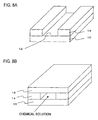
- Figs. 8A and 8B are enlarged fragmentary perspective view of an edge portion of the wafer 10.
- Fig. 8A shows a state where a protection tape 16 is not yet provided
- Fig. 8B shows the wafer 10 with the protection tape 16.
- the scribe line groove 12 may be formed solely on the passivation layer, or on a region including the passivation layer and a portion of the circuit pattern. In either case, since the scribe line groove 12 reaches the wafer edge, a chemical solution or a cleaning solution inevitably intrudes through the edge of the wafer 10 when grinding the back surface, despite covering the wafer front surface with the protection tape 16 as shown in Fig. 8B . This leads to corrosion of the circuit pattern.
- a semiconductor substrate and a plurality of element forming regions formed on a front surface of the semiconductor substrate; wherein a scribe line groove is formed along a periphery of each of the element forming regions; and a plurality of stoppers is provided side-by-side in the scribe line groove, so as to block the scribe line groove against intrusion of a chemical solution or an impurity.
- the stoppers provided in the scribe line groove prevent intrusion of a cleaning solution or an impurity into the scribe line groove, when grinding the back surface or cleaning in a subsequent process with a protection tape attached to the front surface of the semiconductor substrate.
- corrosion of the circuit pattern and adherence of grinding waste thereto can be prevented.
- semiconductor devices of a stabilized quality level can be obtained.
- the scribe line groove may be formed in a grid pattern, and the stopper may be located at an intersection region of the scribe line groove.
- the stopper may be formed in a thickness in a layer stacking direction the same as a thickness of the element forming region in a layer stacking direction.
- the stopper may be formed in a plate shape thinner than a width of the scribe line groove.
- the stopper does not disturb a dicing operation along the scribe line groove, and therefore the plurality of circuit patterns can be smoothly separated.
- the stopper may be formed in a same pattern along four sides of the plurality of element forming regions.
- the plurality of stoppers provided in the scribe line groove prevent intrusion of a cleaning solution or an impurity into the scribe line groove, when grinding the back surface or cleaning in a subsequent process with a protection tape attached on the front surface of the semiconductor substrate.
- corrosion of the circuit pattern and adherence of grinding waste thereto can be prevented.
- semiconductor devices of a stabilized quality level can be obtained.
- the stoppers are formed with the scribe line groove at a same time, the stoppers can be simply formed without the need of introducing an additional process.
- the step of forming the scribe line groove may include exposing the front surface of the semiconductor substrate, through a reticle formed with an opening at a position corresponding to the scribe line groove, but screening a region corresponding to the semiconductor element forming region and the stopper.
- the stopper of a desired shape can be formed simply by arranging a pattern portion of the reticle.
- the step of forming the scribe line groove may include performing a step exposure so as to form an entirety of the scribe line groove on the semiconductor substrate through a single reticle.
- the stopper can be simply formed in the scribe line groove without the need of introducing an additional process.
- the method may further comprise grinding a back surface of the semiconductor substrate, with an entirety of the front surface of the semiconductor substrate covered with a protection tape.
- the stopper provided in the scribe line groove prevent intrusion of a cleaning solution or an impurity into the scribe line groove, when grinding the back surface of the semiconductor substrate.
- corrosion of the circuit pattern and adherence of grinding waste thereto can be prevented.
- the present invention provides a technique of increasing the number of effective chips on a wafer while preventing corrosion of the chips, to thereby provide semiconductor devices of a stabilized quality level.
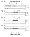
- Figs. 1A to 1D are schematic cross-sectional views sequentially showing a manufacturing process of a semiconductor device of this embodiment.
- Fig. 1A shows a structure of a semiconductor wafer 100 in a manufacturing process.
- an element forming layer 114 including a plurality of circuit patterns is formed on a semiconductor substrate 110, and a passivation layer 116 is formed on the element forming layer 114.
- the passivation layer 116 is constituted of a PSG, silicon nitride, polyimide and so forth.
- a positive type photoresist is formed on the positive passivation layer 116, and a scribe line groove pattern is exposed through a reticle on which the scribe line groove pattern is delineated.
- the pattern exposure is carried out by a stepper capable of performing a step exposure.
- the photoresist is developed to be utilized as a mask for performing a dry etching (RIE: Reactive Ion Etching), so that the passivation layer 116 is delineated in a predetermined pattern ( Fig. 1B ).
- RIE Reactive Ion Etching
- a scribe line groove 112 is formed on the passivation layer 116.
- a stopper 118 is formed in the scribe line groove 112 so as to block the scribe line groove 112.
- a protection tape 120 is adhered on to the passivation layer 116 for protecting the semiconductor wafer 100, upon forming the scribe line groove 112 and the stopper 118 as above ( Fig. 1C ).
- the stopper 118 serves to prevent intrusion of a chemical solution and the like in a subsequent grinding process of a back surface of the semiconductor substrate 110, with a protection tape 120 adhered to the scribe line groove 112.
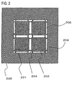
- Fig. 2 is a schematic plan view showing the reticle used for forming a scribe line groove according to an example.
- a pattern portion 201 of the reticle 200 of this embodiment is formed with an opening region 206 which defines a circuit pattern portion 202 and a stopper portion 204. With such the reticle 200, the scribe line pattern can be transferred to the semiconductor wafer 100.
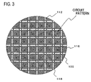
- Fig. 3 is a schematic plan view showing a passivation layer formed in a predetermined pattern with a mask of a photoresist developed after exposing through the reticle of Fig. 2 by a stepper.
- the passivation layer 116 is provided with a scribe line groove 112 formed in a grid pattern, which separates the individual circuit pattern.
- stoppers 118 are provided at intersections of the scribe line grooves 112. With such configuration, the stoppers 118 can protect all the effective circuit patterns (indicated by "a" in Fig. 3 ) as these circuit patterns are placed within a closed space. Therefore, intrusion of a chemical solution or the like into the scribe line groove 112 in a region where effective circuit patterns are located is prevented.
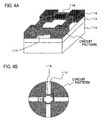
- Figs. 4A and 4B respectively show a structure of stoppers 118.
- Fig. 4A is an enlarged schematic perspective drawing of a portion where the stopper is located.
- the stopper 118 are formed by keeping the corresponding portion from being exposed, like the circuit patterns, when forming the scribe line groove 112. Accordingly, the height of the stopper 118 in a layer stacking direction becomes substantially equivalent to the height of the circuit pattern.
- the stoppers 118 and the protection tape can seal the scribe line groove 112 when the protection tape is adhered thereon in a subsequent process, thereby preventing intrusion of a chemical solution or the like into the scribe line groove 112.
- Fig. 4B is a fragmentary schematic plan view showing a portion where the stopper is located. It is preferable to form the stopper 118 in an appropriate thickness, so that a dicing operation can be smoothly performed when separating the semiconductor wafer 100 along the scribe line groove 112. On the other hand, it is preferable to form the stopper 118 in a sufficient thickness so as to prevent a chemical solution or the like from intruding into the scribe line groove 112.
- the width "D" of the scribe line groove 112 may be 150 ⁇ m, for example.
- the width "d" of the stopper 118 may be set to be thinner than the width "D" of the scribe line groove 112. As a result of such configuration, the dicing operation can be smoothly performed when separating the plurality of chips into individual ones along the scribe line groove 112. In this embodiment, the width "d" of the stopper 118 may be 15 ⁇ m, for example.
- a back surface of the semiconductor substrate 110 is ground.
- the back surface of the semiconductor substrate 110 is subjected to an etching by a chemical solution or by mechanical polishing.
- a chemical solution for the etching for example a fluoronitric acid is employed.
- a fluoronitric acid is employed.
- the circuit pattern ends up being corroded.
- pure water is employed as a cleaning solution.
- grinding waste also intrudes into the scribe line groove together with the water, and sticks to the circuit pattern.
- the stoppers 118 are provided in the scribe line groove 112, which serve to prevent a chemical solution or a cleaning solution from intruding into the scribe line groove 112. Consequently, corrosion of the effective circuit patterns by a chemical solution or the like, as well as adherence of grinding waste to the circuit pattern can be prevented.
- the semiconductor substrate 110 is cut long the scribe line groove 112, so as to divide the circuit patterns into individual ones, thus to obtain a plurality of semiconductor devices.
- the manufacturing process of a semiconductor device according to this embodiment can prevent the circuit pattern from being corroded by a chemical solution or the like, and thereby provides semiconductor devices of a stabilized quality level.
- the stoppers 118 are formed in a plate shape as shown in Fig. 4B in this embodiment, so that the stoppers 118 can be easily cut in the dicing process.
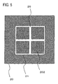
- Fig. 5 is a schematic plan view showing a reticle used for forming a conventional scribe line groove.
- a pattern portion 21 of the conventional reticle 20 is formed with an opening region 26 which defines a circuit pattern portion 202.
- the reticle 200 of this embodiment shown in Fig. 3 is only different from the conventional reticle 20 in that the stopper portion 204 is provided in the pattern portion 201. Therefore, the manufacturing process of a semiconductor device according to this embodiment allows forming a plurality of stoppers 118 in the scribe line groove 112 simply by modifying a pattern of the reticle 200 from a conventional pattern, and thereby preventing the circuit pattern from being corroded by a chemical solution or the like, without introducing an additional process. Further, since the stopper 118 are formed in the scribe line groove 112, there is no need to additionally secure a space for locating the stopper 118, which allows maintain a maximal number of the effective chips per wafer.
- the scribe line groove 112 may be formed through both of the passivation layer 116 and the element forming layer 114 as shown in Fig. 6 .
- the scribe line groove 112 may be formed to a predetermined depth into the element forming layer 114.
- the stopper 118 is formed in a substantially same height as the circuit pattern region, intrusion of a chemical solution or the like can equally be prevented, and equal advantage to that described in the above embodiment can be obtained.
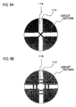
- Figs. 9A and 9B are schematic plan views showing different examples of the stopper. Accordingly, the stopper 118 can be formed in various configurations. Since the stopper 118 can be formed simply by defining a pattern through the reticle 200 according to the embodiment of the present invention, the stopper 118 can be formed in various shapes just by modifying the pattern portion 201 of the reticle 200. According to the invention, disposing a plurality of stoppers 118 side by side as shown in Fig. 9B further ensures the prevention of intrusion of a chemical solution or the like into the scribe line groove 112.
- the stoppers 118 are located in the proximity of an intersection of the scribe line grooves 112, while the stoppers 118 may be disposed in another position than the intersection of the scribe line grooves 112. Providing the stoppers 118 at anywhere in the scribe line groove 112 allows preventing a chemical solution or the like from intruding by a capillary action into any region of the scribe line groove 112, and thus minimizing corrosion of the circuit pattern. Further, while Fig. 3 shows a case where the stoppers 118 are provided at the four corners of all the circuit patterns, the stopper 118 may be provided only around the circuit patterns located along a periphery of the semiconductor wafer 100.
Landscapes
- Mechanical Treatment Of Semiconductor (AREA)
- Dicing (AREA)
- Preparing Plates And Mask In Photomechanical Process (AREA)
Claims (9)
- Verfahren der Herstellung einer Halbleitervorrichtung mit:Ausbildung einer Elementbildungsschicht (114) einschließlich einer Anzahl von Elementbildungsbereichen auf einer Vorderfläche eines Halbleitersubstrats (110),Ausbilden einer Passivierungsschicht (116) auf der Elementbildungsschicht,selektives Entfernen der Passivierungsschicht (116) und Ausbildung einer Ritzliniennut (112) entlang einer Periperie jedes der Elementbildungsbereiche,Schleifen einer Rückfläche des Halbleitersubstrats (110), wobei die Vorderfläche des Halbleitersubstrats mit einem Schutzband (110) bedeckt ist,Entfernen des Schutzbandes (120) undSchneiden des Halbleitersubstrats (110) entlang der Ritzliniennut, wobei das Ausbilden der Ritzliniennut das Ausbilden einer Sperre (118) umfasst, die die Ritzliniennut gegen das Eindringen einer chemischen Lösung oder einer Verunreinigung in die Ritzliniennut blockiert,wobei das Ausbilden der Ritzliniennut das Durchführen einer Stufenfreilegung umfasst, um die Ritzliniennut auf dem Halbleitersubstrat und die Sperre gleichzeitig durch ein einziges Retikel zu bilden, dadurch gekennzeichnet, dassdie Ausbildung der Ritzliniennut das selektive Entfernen der Elementbildungsschicht bis zu einer vorgesehenen Tiefe zusammen mit der Passivierungsschicht umfasst und dass das Ausbilden der Sperre die Ausbildung einer Anzahl von Sperren nebeneinander in der Ritzliniennut umfasst.
- Verfahren nach Anspruch 1, wobei das Ausbilden der Ritzliniennut (112) das Freilegen der Vorderfläche des Halbleitersubstrats über ein Retikel (200) umfasst, das mit einer Öffnung in einer Position ausgebildet ist, die der Ritzliniennut entspricht, und einen Bereich entsprechend dem Halbleiterelementbildungsbereich und der Sperre abschirmt.
- Verfahren nach Anspruch 1, wobei das Ausbilden der Sperre (118) die Ausbildung der Sperre in einer Plattenform umfasst, wobei die Sperre eine Breite aufweist, die dünner ist als die Breite der Ritzliniennut.
- Verfahren nach Anspruch 1, wobei das Ausbilden der Ritzliniennut (112) das Ausbilden der Ritzliniennut in einem Gittermuster umfasst und die Sperre in einem Schnittbereich der Ritzliniennut angeordnet ist.
- Verfahren nach Anspruch 1, wobei die Sperre (118) in einer Dicke mit derselben Dicke wie die Passivierungsschicht in einer Schichtstapelrichtung ausgebildet wird.
- Verfahren nach Anspruch 1, wobei die Sperre (118) in demselben Muster entlang von vier Seiten jedes der Anzahl von Elementbildungsbereichen ausgebildet wird.
- Verfahren nach Anspruch 1, wobei das Ausbilden der Sperre (118) das Ausbilden der Sperre derart umfasst, dass eine obere Fläche der Sperre koplanar mit der oberen Fläche der Passivierungsschicht ist.
- Verfahren nach Anspruch 1, mit ferner dem selektiven Entfernen der Elementbildungsschicht entlang einer Peripherie jedes der Elementbildungsbereiche, um ferner die Ritzliniennut (112) zu bilden.
- Verfahren nach Anspruch 1, wobei die Sperre einen gesamten Querschnitt der Ritzliniennut füllt.
Applications Claiming Priority (2)
| Application Number | Priority Date | Filing Date | Title |
|---|---|---|---|
| JP2004093782A JP2005285853A (ja) | 2004-03-26 | 2004-03-26 | 半導体ウェハ、半導体ウェハの製造方法、および半導体装置の製造方法 |
| JP2004093782 | 2004-03-26 |
Publications (3)
| Publication Number | Publication Date |
|---|---|
| EP1580806A2 EP1580806A2 (de) | 2005-09-28 |
| EP1580806A3 EP1580806A3 (de) | 2006-03-29 |
| EP1580806B1 true EP1580806B1 (de) | 2011-10-05 |
Family
ID=34858529
Family Applications (1)
| Application Number | Title | Priority Date | Filing Date |
|---|---|---|---|
| EP04029452A Expired - Lifetime EP1580806B1 (de) | 2004-03-26 | 2004-12-13 | Halbleitersubstrat, Verfahren zur Herstellung einem Halbleitersubstrat und einer Halbleitervorrichtungen |
Country Status (4)
| Country | Link |
|---|---|
| US (2) | US20050224920A1 (de) |
| EP (1) | EP1580806B1 (de) |
| JP (1) | JP2005285853A (de) |
| CN (1) | CN100355035C (de) |
Families Citing this family (12)
| Publication number | Priority date | Publication date | Assignee | Title |
|---|---|---|---|---|
| JP4837971B2 (ja) * | 2005-10-07 | 2011-12-14 | ルネサスエレクトロニクス株式会社 | 半導体装置の製造方法 |
| KR100813244B1 (ko) * | 2006-07-11 | 2008-03-13 | 삼성에스디아이 주식회사 | 리포머 버너 |
| US8648444B2 (en) * | 2007-11-29 | 2014-02-11 | Taiwan Semiconductor Manufacturing Company, Ltd. | Wafer scribe line structure for improving IC reliability |
| JP2011129551A (ja) * | 2009-12-15 | 2011-06-30 | Panasonic Corp | 半導体装置及びその製造方法 |
| JP5401301B2 (ja) * | 2009-12-28 | 2014-01-29 | ルネサスエレクトロニクス株式会社 | 半導体装置の製造方法及び半導体装置 |
| US8884402B2 (en) * | 2010-04-28 | 2014-11-11 | United Microelectronics Corp. | Circuit layout structure |
| CN102610578A (zh) * | 2012-03-19 | 2012-07-25 | 无锡纳克斯半导体材料有限公司 | 一种矩阵式蓝宝石衬底及其制备方法 |
| US9202754B2 (en) | 2012-04-23 | 2015-12-01 | Seagate Technology Llc | Laser submounts formed using etching process |
| WO2016204170A1 (ja) * | 2015-06-19 | 2016-12-22 | 株式会社村田製作所 | ウエハレベルパッケージ及びウエハレベルチップサイズパッケージ |
| US20180015569A1 (en) * | 2016-07-18 | 2018-01-18 | Nanya Technology Corporation | Chip and method of manufacturing chips |
| CN108346555A (zh) * | 2017-01-23 | 2018-07-31 | 中芯国际集成电路制造(上海)有限公司 | 一种半导体器件及其制作方法 |
| KR102898633B1 (ko) * | 2020-12-17 | 2025-12-09 | 삼성전자주식회사 | 반도체 장치 및 반도체 패키지 |
Citations (1)
| Publication number | Priority date | Publication date | Assignee | Title |
|---|---|---|---|---|
| US20010035567A1 (en) * | 2000-03-27 | 2001-11-01 | Moyuru Fujii | Semiconductor wafer having a bank on a scribe line |
Family Cites Families (11)
| Publication number | Priority date | Publication date | Assignee | Title |
|---|---|---|---|---|
| JPS519688A (en) | 1974-07-15 | 1976-01-26 | Tokyo Shibaura Electric Co | Handotaisochino seizohoho |
| JPS5178687A (ja) | 1974-12-28 | 1976-07-08 | Fujitsu Ltd | Handotaisochinoseizohoho |
| US5071792A (en) * | 1990-11-05 | 1991-12-10 | Harris Corporation | Process for forming extremely thin integrated circuit dice |
| JPH05109688A (ja) | 1991-10-18 | 1993-04-30 | Fujitsu Ltd | 半導体装置の製造方法 |
| US5789302A (en) * | 1997-03-24 | 1998-08-04 | Siemens Aktiengesellschaft | Crack stops |
| US6627917B1 (en) * | 2000-04-25 | 2003-09-30 | Medtronic, Inc. | Method and apparatus for wafer-level burn-in |
| US6964924B1 (en) * | 2001-09-11 | 2005-11-15 | Lsi Logic Corporation | Integrated circuit process monitoring and metrology system |
| CN1287435C (zh) * | 2002-06-27 | 2006-11-29 | 松下电器产业株式会社 | 半导体装置及其制造方法 |
| JP3722809B2 (ja) * | 2002-06-27 | 2005-11-30 | 松下電器産業株式会社 | 半導体装置及びその製造方法 |
| JP2004253678A (ja) | 2003-02-21 | 2004-09-09 | Renesas Technology Corp | 半導体装置の製造方法 |
| US20070102791A1 (en) * | 2005-11-07 | 2007-05-10 | Ping-Chang Wu | Structure of multi-layer crack stop ring and wafer having the same |
-
2004
- 2004-03-26 JP JP2004093782A patent/JP2005285853A/ja active Pending
- 2004-12-13 EP EP04029452A patent/EP1580806B1/de not_active Expired - Lifetime
-
2005
- 2005-01-21 US US11/038,029 patent/US20050224920A1/en not_active Abandoned
- 2005-02-22 CN CNB2005100083715A patent/CN100355035C/zh not_active Expired - Fee Related
-
2007
- 2007-10-31 US US11/980,573 patent/US7618877B2/en not_active Expired - Fee Related
Patent Citations (1)
| Publication number | Priority date | Publication date | Assignee | Title |
|---|---|---|---|---|
| US20010035567A1 (en) * | 2000-03-27 | 2001-11-01 | Moyuru Fujii | Semiconductor wafer having a bank on a scribe line |
Also Published As
| Publication number | Publication date |
|---|---|
| EP1580806A3 (de) | 2006-03-29 |
| EP1580806A2 (de) | 2005-09-28 |
| US20080070381A1 (en) | 2008-03-20 |
| US20050224920A1 (en) | 2005-10-13 |
| CN100355035C (zh) | 2007-12-12 |
| JP2005285853A (ja) | 2005-10-13 |
| CN1674233A (zh) | 2005-09-28 |
| US7618877B2 (en) | 2009-11-17 |
Similar Documents
| Publication | Publication Date | Title |
|---|---|---|
| US7618877B2 (en) | Semiconductor wafer, method of manufacturing the same, and method of manufacturing a semiconductor device | |
| US7052975B2 (en) | Semiconductor chip and fabrication method thereof | |
| US6624505B2 (en) | Packaged integrated circuits and methods of producing thereof | |
| KR101609004B1 (ko) | 반도체 다이 준비 방법 및 반도체 구조물 | |
| US8178421B2 (en) | Method of fabricating semiconductor device | |
| US6887771B2 (en) | Semiconductor device and method for fabricating the same | |
| US7042105B2 (en) | Methods for dicing wafer stacks to provide access to interior structures | |
| US7709295B2 (en) | Method of manufacturing semiconductor device | |
| US5017512A (en) | Wafer having a dicing area having a step region covered with a conductive layer and method of manufacturing the same | |
| US6734040B2 (en) | Method of manufacturing semiconductor devices | |
| US8030180B2 (en) | Method of manufacturing a semiconductor device | |
| US4967259A (en) | Wafer having a dicing area having a step region covered with a conductive layer and method of manufacturing the same | |
| US12046513B2 (en) | Die corner protection by using polymer deposition technology | |
| JP2005244094A (ja) | 半導体装置の製造方法および半導体装置 | |
| JP2008028243A (ja) | 半導体装置 | |
| US20200402956A1 (en) | Method for manufacturing a semiconductor package having five-side protection | |
| US7411268B2 (en) | Fabricating deeper and shallower trenches in semiconductor structures | |
| US20020062549A1 (en) | Optimized metal fuse process | |
| CN112802819B (zh) | 半导体元件及其制作方法 | |
| JPH1022236A (ja) | 半導体装置およびその製造方法 | |
| US20050014364A1 (en) | Method of suppressing the effect of shining spots present at the edge of a wafer | |
| KR20070051088A (ko) | 크랙방지용 홈을 구비한 반도체 웨이퍼 및 반도체 웨이퍼절단방법 | |
| JP2000031452A (ja) | 半導体装置およびその製造方法 | |
| CN120149266A (zh) | 蚀刻管芯切割系统和相关方法 | |
| US20030030130A1 (en) | Semiconductor device with mechanical stress protection during wafer cutting, and manufacturing process thereof |
Legal Events
| Date | Code | Title | Description |
|---|---|---|---|
| PUAI | Public reference made under article 153(3) epc to a published international application that has entered the european phase |
Free format text: ORIGINAL CODE: 0009012 |
|
| AK | Designated contracting states |
Kind code of ref document: A2 Designated state(s): AT BE BG CH CY CZ DE DK EE ES FI FR GB GR HU IE IS IT LI LT LU MC NL PL PT RO SE SI SK TR |
|
| AX | Request for extension of the european patent |
Extension state: AL BA HR LV MK YU |
|
| PUAL | Search report despatched |
Free format text: ORIGINAL CODE: 0009013 |
|
| AK | Designated contracting states |
Kind code of ref document: A3 Designated state(s): AT BE BG CH CY CZ DE DK EE ES FI FR GB GR HU IE IS IT LI LT LU MC NL PL PT RO SE SI SK TR |
|
| AX | Request for extension of the european patent |
Extension state: AL BA HR LV MK YU |
|
| 17P | Request for examination filed |
Effective date: 20060224 |
|
| AKX | Designation fees paid |
Designated state(s): DE FR |
|
| RAP1 | Party data changed (applicant data changed or rights of an application transferred) |
Owner name: RENESAS ELECTRONICS CORPORATION |
|
| GRAP | Despatch of communication of intention to grant a patent |
Free format text: ORIGINAL CODE: EPIDOSNIGR1 |
|
| GRAS | Grant fee paid |
Free format text: ORIGINAL CODE: EPIDOSNIGR3 |
|
| GRAA | (expected) grant |
Free format text: ORIGINAL CODE: 0009210 |
|
| AK | Designated contracting states |
Kind code of ref document: B1 Designated state(s): DE FR |
|
| REG | Reference to a national code |
Ref country code: DE Ref legal event code: R096 Ref document number: 602004034627 Country of ref document: DE Effective date: 20120105 |
|
| PLBE | No opposition filed within time limit |
Free format text: ORIGINAL CODE: 0009261 |
|
| STAA | Information on the status of an ep patent application or granted ep patent |
Free format text: STATUS: NO OPPOSITION FILED WITHIN TIME LIMIT |
|
| 26N | No opposition filed |
Effective date: 20120706 |
|
| REG | Reference to a national code |
Ref country code: DE Ref legal event code: R097 Ref document number: 602004034627 Country of ref document: DE Effective date: 20120706 |
|
| PGFP | Annual fee paid to national office [announced via postgrant information from national office to epo] |
Ref country code: DE Payment date: 20121205 Year of fee payment: 9 |
|
| PGFP | Annual fee paid to national office [announced via postgrant information from national office to epo] |
Ref country code: FR Payment date: 20130107 Year of fee payment: 9 |
|
| REG | Reference to a national code |
Ref country code: DE Ref legal event code: R119 Ref document number: 602004034627 Country of ref document: DE |
|
| REG | Reference to a national code |
Ref country code: FR Ref legal event code: ST Effective date: 20140829 |
|
| REG | Reference to a national code |
Ref country code: DE Ref legal event code: R119 Ref document number: 602004034627 Country of ref document: DE Effective date: 20140701 |
|
| PG25 | Lapsed in a contracting state [announced via postgrant information from national office to epo] |
Ref country code: DE Free format text: LAPSE BECAUSE OF NON-PAYMENT OF DUE FEES Effective date: 20140701 |
|
| PG25 | Lapsed in a contracting state [announced via postgrant information from national office to epo] |
Ref country code: FR Free format text: LAPSE BECAUSE OF NON-PAYMENT OF DUE FEES Effective date: 20131231 |