EP1580764A1 - Metalldichtung, Verfahren zur Fertigung einer Metalldichtung und Behälter zum Einschluss von radioaktiven Stoffen - Google Patents
Metalldichtung, Verfahren zur Fertigung einer Metalldichtung und Behälter zum Einschluss von radioaktiven Stoffen Download PDFInfo
- Publication number
- EP1580764A1 EP1580764A1 EP04007344A EP04007344A EP1580764A1 EP 1580764 A1 EP1580764 A1 EP 1580764A1 EP 04007344 A EP04007344 A EP 04007344A EP 04007344 A EP04007344 A EP 04007344A EP 1580764 A1 EP1580764 A1 EP 1580764A1
- Authority
- EP
- European Patent Office
- Prior art keywords
- inner cover
- metal gasket
- ring
- center
- cover
- Prior art date
- Legal status (The legal status is an assumption and is not a legal conclusion. Google has not performed a legal analysis and makes no representation as to the accuracy of the status listed.)
- Granted
Links
- 229910052751 metal Inorganic materials 0.000 title claims abstract description 107
- 239000002184 metal Substances 0.000 title claims abstract description 107
- 239000012857 radioactive material Substances 0.000 title claims description 32
- 238000004519 manufacturing process Methods 0.000 title claims description 12
- XLYOFNOQVPJJNP-UHFFFAOYSA-N water Substances O XLYOFNOQVPJJNP-UHFFFAOYSA-N 0.000 claims abstract description 80
- 239000000463 material Substances 0.000 claims description 50
- 238000004804 winding Methods 0.000 claims description 37
- 239000000446 fuel Substances 0.000 claims description 16
- 238000000034 method Methods 0.000 claims description 9
- 238000007789 sealing Methods 0.000 description 19
- 230000007797 corrosion Effects 0.000 description 8
- 238000005260 corrosion Methods 0.000 description 8
- 229910052782 aluminium Inorganic materials 0.000 description 6
- XAGFODPZIPBFFR-UHFFFAOYSA-N aluminium Chemical compound [Al] XAGFODPZIPBFFR-UHFFFAOYSA-N 0.000 description 6
- PXHVJJICTQNCMI-UHFFFAOYSA-N Nickel Chemical compound [Ni] PXHVJJICTQNCMI-UHFFFAOYSA-N 0.000 description 4
- 230000004048 modification Effects 0.000 description 4
- 238000012986 modification Methods 0.000 description 4
- 239000011347 resin Substances 0.000 description 3
- 229920005989 resin Polymers 0.000 description 3
- 229910000975 Carbon steel Inorganic materials 0.000 description 2
- RYGMFSIKBFXOCR-UHFFFAOYSA-N Copper Chemical compound [Cu] RYGMFSIKBFXOCR-UHFFFAOYSA-N 0.000 description 2
- 229910000990 Ni alloy Inorganic materials 0.000 description 2
- BQCADISMDOOEFD-UHFFFAOYSA-N Silver Chemical compound [Ag] BQCADISMDOOEFD-UHFFFAOYSA-N 0.000 description 2
- 239000010962 carbon steel Substances 0.000 description 2
- 238000001816 cooling Methods 0.000 description 2
- 229910052802 copper Inorganic materials 0.000 description 2
- 239000010949 copper Substances 0.000 description 2
- 238000005516 engineering process Methods 0.000 description 2
- 239000007789 gas Substances 0.000 description 2
- 229910001026 inconel Inorganic materials 0.000 description 2
- 229910052759 nickel Inorganic materials 0.000 description 2
- 229910001235 nimonic Inorganic materials 0.000 description 2
- 239000003758 nuclear fuel Substances 0.000 description 2
- 230000003647 oxidation Effects 0.000 description 2
- 238000007254 oxidation reaction Methods 0.000 description 2
- 230000008569 process Effects 0.000 description 2
- 229910052709 silver Inorganic materials 0.000 description 2
- 239000004332 silver Substances 0.000 description 2
- 239000010935 stainless steel Substances 0.000 description 2
- 229910001220 stainless steel Inorganic materials 0.000 description 2
- 238000001291 vacuum drying Methods 0.000 description 2
- ZOXJGFHDIHLPTG-UHFFFAOYSA-N Boron Chemical compound [B] ZOXJGFHDIHLPTG-UHFFFAOYSA-N 0.000 description 1
- UFHFLCQGNIYNRP-UHFFFAOYSA-N Hydrogen Chemical compound [H][H] UFHFLCQGNIYNRP-UHFFFAOYSA-N 0.000 description 1
- ZOKXTWBITQBERF-UHFFFAOYSA-N Molybdenum Chemical compound [Mo] ZOKXTWBITQBERF-UHFFFAOYSA-N 0.000 description 1
- 230000000712 assembly Effects 0.000 description 1
- 238000000429 assembly Methods 0.000 description 1
- 230000004888 barrier function Effects 0.000 description 1
- 229910052796 boron Inorganic materials 0.000 description 1
- 238000002485 combustion reaction Methods 0.000 description 1
- 239000002131 composite material Substances 0.000 description 1
- 238000010276 construction Methods 0.000 description 1
- 238000010586 diagram Methods 0.000 description 1
- 230000004992 fission Effects 0.000 description 1
- 239000001307 helium Substances 0.000 description 1
- 229910052734 helium Inorganic materials 0.000 description 1
- SWQJXJOGLNCZEY-UHFFFAOYSA-N helium atom Chemical compound [He] SWQJXJOGLNCZEY-UHFFFAOYSA-N 0.000 description 1
- 239000001257 hydrogen Substances 0.000 description 1
- 229910052739 hydrogen Inorganic materials 0.000 description 1
- 230000001050 lubricating effect Effects 0.000 description 1
- 238000003754 machining Methods 0.000 description 1
- 150000002739 metals Chemical class 0.000 description 1
- 229910052750 molybdenum Inorganic materials 0.000 description 1
- 239000011733 molybdenum Substances 0.000 description 1
- 230000005855 radiation Effects 0.000 description 1
- 238000012958 reprocessing Methods 0.000 description 1
- 239000007787 solid Substances 0.000 description 1
Images


Classifications
-
- G—PHYSICS
- G21—NUCLEAR PHYSICS; NUCLEAR ENGINEERING
- G21F—PROTECTION AGAINST X-RADIATION, GAMMA RADIATION, CORPUSCULAR RADIATION OR PARTICLE BOMBARDMENT; TREATING RADIOACTIVELY CONTAMINATED MATERIAL; DECONTAMINATION ARRANGEMENTS THEREFOR
- G21F5/00—Transportable or portable shielded containers
- G21F5/06—Details of, or accessories to, the containers
- G21F5/12—Closures for containers; Sealing arrangements
Definitions
- the present invention relates to a technology for sealing a radioactive-material container.
- a nuclear fuel assembly that is at the end of a nuclear fuel cycle and finishes its combustion is called a recycle fuel assembly.
- the recycle fuel assembly is cooled at a cooling pit of a nuclear power plant for a long period of time because the recycle fuel assembly contains highly radioactive materials such as fission product (FP) and requires thermal cooling.
- FP fission product
- the recycle fuel assembly is contained in a radioactive-material container, and conveyed to a reprocessing facility to be stored. Since the radioactive-material container contains highly radioactive materials, a strict care should be paid on its sealing for a storing period of 40 years to 60 years.
- the radioactive-material container is sealed by using a metal gasket between a lid and a body.
- An example of a structure for securing the sealing of the metal gasket is a single-ring-type metal gasket that suppresses a leak by forming a solid lubricating clad between an inner cover and an outer cover (see Japanese Utility Model Application Laid-Open, H5-75154).
- the conventional metal gasket formed by a double structure, where the outer cover is configured to grasp a ring-shaped coil spring, the water collects inside the inner and the outer rings and it is hard to drain the water to the outside.
- the conventional metal gasket is configured to wind a plate-shaped inner cover around the coil spring, it is necessary to wind the inner cover in such a manner that an opening faces the outside when manufacturing. Consequently, it is difficult to have the openings of both inner rings faced the inside to make it easy to remove the water inside the metal gasket.
- the metal gasket according to one aspect of the present invention includes a coil spring that forms a ring; an inner cover that covers the coil spring; and an outer cover that covers the inner cover.
- the inner cover has a hole for draining water from the metal gasket.
- the metal gasket according to another aspect of the present invention includes a first coil spring that forms a first ring and a second coil spring that forms a second ring, the first ring and the second ring arranged concentrically with a different hoop diameter; a first inner cover that covers the first coil spring; a second inner cover that covers the second coil spring; and an outer cover that covers the first inner cover and the second inner cover.
- the first inner cover has a hole for draining water from the metal gasket.
- the metal gasket according to still another aspect of the present invention includes an inner cover that is formed by winding a plate material having two edges in such a manner that the two edges have an overlap, where the inner cover forms a ring and functions as a spring; and an outer cover that covers the inner cover.
- the inner cover has a hole for draining water from the metal gasket.
- the metal gasket according to still another aspect of the present invention includes a first inner cover that is formed by winding a first plate material having two first edges in such a manner that the two first edges have an overlap making a first circle, where the first inner cover forms a first ring and functions as a spring; a second inner cover that is formed by winding a second plate material having two second edges in such a manner that the two second edges have an overlap making a second circle, where the second inner cover forms a second ring that is concentric to the first ring and functions as a spring; and an outer cover that covers the first inner cover and the second inner cover.
- the first inner cover has a first hole and the second inner cover has a second hole, for draining water from the metal gasket.
- the method of manufacturing a metal gasket includes making a hole for draining water from the metal gasket in a plate material; forming a ring with a coil spring; forming an inner cover by winding the plate material around the ring; and winding an outer cover around the inner cover.
- the method of manufacturing a metal gasket includes making a first hole for draining water from the metal gasket in a first plate material; making a second hole for draining water from the metal gasket in a second plate material; forming a first ring with a first coil spring and a second ring with a second coil spring; forming a first inner cover by winding the first plate material around a surface of the first coil spring; forming a second inner cover by winding the second plate material around a surface of the second coil spring; and winding an outer cover around the first inner cover and the second inner cover.
- the method of manufacturing a metal gasket includes making a hole for draining water from the metal gasket in a plate material, the plate material having two edges; forming an inner cover by winding the plate material in such a manner that the two edges have an overlap to make a ring that functions as a spring; and winding an outer cover around the inner cover.
- the method of manufacturing a metal gasket includes making a first hole for draining water from the metal gasket in a first plate material, the first plate material having two first edges; making a second hole for removing water from the metal gasket in a second plate material, the second plate material having two second edges; forming a first inner cover by winding the first plate material in such a manner that the two first edges have an overlap making a first circle, where the first inner cover forms a first ring that functions as a spring; forming a second inner cover by winding the second plate material in such a manner that the two second edges have an overlap making a second circle, where the second inner cover forms a second ring that is concentric to the first ring and functions as a spring; and winding an outer cover around the first inner cover and the second inner cover.
- the radioactive-material container includes a body that includes a cavity to accommodate a recycle fuel assembly; a lid that is arranged on an opening of the cavity; and the metal gasket according to the above aspects between the body and the lid.
- Exemplary embodiments of a metal gasket, a method of manufacturing the metal gasket, and a radioactive-material container according to the present invention will be explained below in detail with reference to the accompanying diagrams.
- the present invention is not limited to the following embodiments, and the components of the following embodiments include components that a person skilled in the art assumes easily or substantially same components.
- An applicable scope of a metal gasket according to the present invention is not especially limited, and, for example, the metal gasket may be applied to a sealing part of a radioactive-material container, and a sealing part of a reactor container.
- the metal gasket is suited to an application that requires maintaining the sealing performance for decades in the comparatively-high-temperature environment, more especially a radioactive-material container that accommodates the recycle fuel assembly, is conveyed, and stores the recycle fuel assembly for a long period of time.
- Fig. 1 is a cross section of a radioactive-material container 500 according to a first embodiment of the present invention.
- Fig. 2 is a partial enlarged-view of the radioactive-material container 500.
- the radioactive-material container 500 includes a body 501, which is made of stainless or carbon steel, an external cylinder 502, which composes an external surface of the radioactive-material container 500, a resin 503, which is a polymeric material that contains hydrogen and fills a space between the body 501 and the external cylinder 502, a bottom plate 505, which is welded to the bottom of the body 501 and in which a resin 504 is enclosed, and a lid 520, which is arranged on an opening 509o of a cavity 509.
- the opening 509o corresponds to a flange member 506, which is welded to the body 501.
- the lid 520 includes a primary lid 507 and a secondary lid 508.
- the flange member 506 may be formed to unite with the body 501.
- a basket 513 that accommodates the recycle fuel assembly is arranged inside the cavity 509 of the body 501.
- the primary lid 507 and the secondary lid 508 are fixed using bolts 510, 511 on the flange member 506, and a resin 512 is enclosed in the secondary lid 508.
- the basket 513 is composed of a plurality of cells that is formed of boron/aluminum composite.
- the cavity 509 is filled with negative-pressure helium gas while a space between the primary lid 507.
- the secondary lid 508 is positive pressured, so that a pressure barrier is formed between the inside and the outside of the radioactive-material container 500.
- a hole 514 is arranged in the secondary lid 508 to measure the pressure of a space between the primary lid 507 and the secondary lid 508, and a pressure sensor 515 is arranged on the outlet of the hole 514.
- a valve is arranged in the primary lid 507 to replace the gas inside the radioactive-material container 500, and covered with a valve cover.
- a metal gasket 20 that is heat resistant, corrosion resistant, and highly durable is used because the gaps must be sealed for a long period of time.
- the metal gasket 20 is fixed to a gasket gap 525 that is formed by machining. For example, when the secondary lid 508 and the body 501 are fixed, the metal gasket 20 is tightened and transformed, and a sealing function is exerted.
- Fig. 3 is a schematic for illustrating a sealing structure 10 of a metal gasket 20 according to the first embodiment.
- a feature of the sealing structure 10 is that a hole for draining water is made in an inner cover.
- Various types of metal gaskets are applied to the present invention.
- the metal gasket 20, shown in Fig. 4 is so-called double ring type and includes two coil springs 30a, 30b.
- the coil springs 30a, 30b have the different hoop diameters Df, are arranged concentrically, and covered with an outer cover 50.
- Other examples are the metal gasket 20', shown in Fig. 5, that includes an outer cover 50' with a flat upper part, and a single-type metal gasket (not shown).
- the coil springs 30a, 30b may be called a coil spring 30 or coil springs 30 in the following explanation for convenience.
- the sealing structure 10 and the metal gasket 20 shown in Fig. 3 is arranged between the secondary lid 508 and the flange member 506 of the body 501, and may be arranged between the primary lid 507 and the flange member 506of the body 501.
- inner covers 40a, 40b respectively cover the coil springs 30a, 30b that are substantially circular, so that an outer ring 70a and an inner ring 70b are formed.
- an outer cover 50 covers the outer ring 70a and the inner ring 70b.
- the outer cover 50 has bolt holes and bolts penetrate the bolt holes to fix the metal gasket 20 on the gasket gap 525.
- the inner covers 40a, 40b may be called an inner cover 40 or inner covers 40 in the following explanation for convenience.
- a water drain hole 101 a which is a hole for draining water, is made where the inner cover 40a is not covered with the outer cover 50, namely, where the inner cover 40a is not disturbed by the outer cover 50, and is made in the inner cover 40a to face the center of the body 501. Therefore, the water drain hole 101 a is made only in the inner cover 40a. After the water drain hole 101 a is made in the inner cover 40a, the inner covers 40a, 40b are wound round the coil springs 30a, 30b respectively to have a ring section.
- the hoop diameter is approximately 2 meters
- the sectional diameters D of the outer ring 70a and the inner ring 70b are approximately 5.5 millimeters
- the thickness of the outer cover 50 is 0.4 millimeter
- the thickness of the inner cover 40s is 0.4 millimeter.
- a soft metal such as aluminum, silver, copper, and nickel
- a nickel alloy such as Inconel (a registered trademark), which is corrosion resistant and oxidation resistant at high temperature, or stainless, is used to maintain the elasticity in a high-temperature environment.
- Nimonic which has a high Co content, or the like may be used to improve the durability at higher temperature.
- the secondary lid 508 As a material of the secondary lid 508, the primary lid 507, and the body 501, stainless steel or carbon steel is used to block off the radiation and maintain the mechanical strength.
- the secondary lid 508, the primary lid 507, and the body 501 make a contact with the outer cover 50, which is made of a soft metal. Therefore, for example, when the outer cover 50 makes a contact with the body 501, a voltage potential difference is caused by a contact between the different metals, so that the galvanic corrosion occurs and the air tightness is broken.
- SUS317 or SUS625, which contains molybdenum is used as a material of the secondary lid 508 and the body 501.
- SUS317 and SUS625 have a good weldability and are generally suited to an application that has a lot of parts to be welded, such as a radioactive-material container.
- SUS625, SUS314, SUS316, SUS326, and SUS345 may be used as an alternative to SUS 317 and SUS625.
- a sealing surface 90 may be made on the secondary lid 508 and the body 501 to have a bulge portion using the same material.
- Aluminum may be used as a material of the outer cover 50.
- Aluminum has the higher corrosion potential than SUS317 or SUS 625, which is a material of the secondary lid 508 and the body 501. Therefore, when the outer cover 50 is made of aluminum, the outer cover 50 is corroded more easily than the secondary lid 508 and the body 501. However the outer cover 50 can be replaced more easily than the secondary lid 508 and the body 501, so that the secondary lid 508 and the body 501 can be protected from the galvanic corrosion.
- the same explanation is applied to a combination of the primary lid 507 and the body 510.
- Fig. 6 is a perspective view of a coil spring of the metal gasket according to the first embodiment of the present invention.
- Fig. 7 is a side view of the coil spring of the metal gasket according to the first embodiment.
- the coil spring 30 is formed by winding a wire material closely. If the wire material is not wounded closely, when the medal gasket 20 is sealed and squashed, the spring coil 30 can not push back the inner cover 40 and the outer cover 50 with a uniform force and the seal performance can not be exerted for a certain distance in long-time usage.
- the coil spring 30 is required to have the larger wire diameter d, that is, to have the higher flexural rigidity.
- the wire diameter d of the coil spring 30 gets larger, winding the wire gets harder and the winding diameter D1 of the coil spring 30 gets larger. Consequently, when the metal gasket requires a high seal-pressure, the cross-sectional diameter D of the metal gasket 20 gets larger comparing to that of what requires a low seal-pressure.
- the flexural rigidity of the coil spring 30 indicates how hard to transform the coil spring 30 to the radial direction when force P is acted on the coil spring 30 to the radial direction.
- the radioactive-material container 500 is lifted up from the pool and the water is removed from the radioactive-material container 500 by vacuum drying.
- the water enters inside the coil springs 30a, 30b.
- the water enters inside the coil spring 30b easily because the inner cover 40b has an opening 40s inside the metal gasket 20. Even if the inner cover 40a does not have the opening, the water enters from a gap between the outer cover 50 and the inner cover 40a and collects inside the coil spring 30a or the water enters from a surface between the outer cover 50 and the inner cover 40a and collects inside.
- the water that collects inside the metal gasket 20 is removed.
- the water In the outer ring 70a, the water is removed from the water drain hole 101 a to the outside.
- the inner ring 70b In the inner ring 70b, the water is removed from the opening 40s and the inner cover 40b is required to have a hole for draining the water.
- the inner cover 40b is required to have a water drain hole 101b, which is a hole for draining the water from a gap between the inner cover 40b and the outer cover 50, in the cases of:
- the inner covers 40 are wound round the coil springs30. Consequently, the water drain holes 101 can be made in the inner covers 40 without paying an attention not to damage the coil springs 30.
- the water drain hole 101 a is made to face the center of the body 501, substantially corresponding to the direction of a line L that joins a center of the ring outer ring 70a to that of the outer ring 70b, because if the water drain hole 101 a faces obliquely downward, the opening of the water drain hole opening may be covered with the sealing surface 90 and may not work.
- the angle between the direction that the water drain hole 101 faces and the line L is ⁇ 45 degrees.
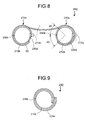
- Fig. 8 is a cross section of a metal gasket 200 according to a second embodiment of the present invention.
- Fig. 9 is a cross section of a metal gasket according to a modification of the second embodiment.
- the metal gasket 200 includes inner covers 210a, 210b and the inner covers 210a, 201b have a ring section, have the different hoop diameters, and are arranged concentrically.
- the hoop diameter of the inner cover 210a is larger than that of the inner cover 210b.
- An outer cover 50 covers the inner covers 210a, 210b and forms a double-ring.
- a metal gasket that is applied to the present invention is not limited to the type of the metal gasket 200, but may be a metal gasket 250 so-called a single type metal gasket.
- the metal gasket 250 includes an outer cover 260 and an inner cover 210c that has a water drain hole 230c, which is a hole for draining the water.
- the inner cover 210a, the inner cover 210b, and the inner cover 210c may be called an inner cover 210 or inner covers 210 and the outer cover 220A and the outer cover 220C may be called an outer cover 220 for convenience.
- a soft metal such as aluminum, silver, copper, and nickel is used to ensure the sealing performance.
- a nickel alloy such as Inconel (registered trademark), which is corrosion resistant and oxidation resistant at high temperature, is used to maintain the elasticity.
- Nimonic registered trademark
- the inner covers 210 are formed substantially circular and to have a ring section by winding a plate material while overlapping an edge of the plate material with another edge, so that the inner covers 210 works as a spring.
- Water drain holes 230a, 230a', and 230b are formed in the inner covers 210a and 210b.
- the water drain holes 230a and 230a' formed in the inner cover 210a is for draining the water from the metal gasket 200.
- the water drain hole 230b is for draining the water from a gap between the inner cover 210b and the outer cover 50.
- the inner covers 210 may have a plurality of holes for draining the water.
- the water drain holes 230a, 230b are made to face the center of the body 501 and arranged at substantially middle of the height of the metal gasket 200.
- the water drain holes 230a, 230b are made below, the water drain holes 230a, 230b are disturbed by the outer cover 220A, therefore the outer cover 200A needs to have a hole for draining the water. If the water drain holes 230a, 230b are made close to a sealing surface, the water easily enters between the outer cover 220A and the sealing surface but it is hard to remove the water. Preferably, the water drain holes 230a, 230b are arranged to make an angle of at most 45 degrees to a line I, which joins a center of an outer ring 270a to a center of an inner ring 270b.
- the inner ring 270b has the overlapped part 210s is arranged inside the metal gasket 200. Therefore, the water drain hole 230a' needs to be arranged where the water drain hole 230a' is not covered with the overlapped part 210s when the overlapped part 210s slides by sealing.
- the metal gasket 250 is formed in the following order:
- the seal performance can be sufficiently exerted for a long time by removing the water inside the metal gasket.
Landscapes
- Physics & Mathematics (AREA)
- Engineering & Computer Science (AREA)
- General Engineering & Computer Science (AREA)
- High Energy & Nuclear Physics (AREA)
- Gasket Seals (AREA)
Priority Applications (2)
| Application Number | Priority Date | Filing Date | Title |
|---|---|---|---|
| AT04007344T ATE548736T1 (de) | 2004-03-26 | 2004-03-26 | Metalldichtung, verfahren zur fertigung einer metalldichtung und behälter zum einschluss von radioaktiven stoffen |
| EP04007344A EP1580764B1 (de) | 2004-03-26 | 2004-03-26 | Metalldichtung, Verfahren zur Fertigung einer Metalldichtung und Behälter zum Einschluss von radioaktiven Stoffen |
Applications Claiming Priority (1)
| Application Number | Priority Date | Filing Date | Title |
|---|---|---|---|
| EP04007344A EP1580764B1 (de) | 2004-03-26 | 2004-03-26 | Metalldichtung, Verfahren zur Fertigung einer Metalldichtung und Behälter zum Einschluss von radioaktiven Stoffen |
Publications (2)
| Publication Number | Publication Date |
|---|---|
| EP1580764A1 true EP1580764A1 (de) | 2005-09-28 |
| EP1580764B1 EP1580764B1 (de) | 2012-03-07 |
Family
ID=34854635
Family Applications (1)
| Application Number | Title | Priority Date | Filing Date |
|---|---|---|---|
| EP04007344A Expired - Lifetime EP1580764B1 (de) | 2004-03-26 | 2004-03-26 | Metalldichtung, Verfahren zur Fertigung einer Metalldichtung und Behälter zum Einschluss von radioaktiven Stoffen |
Country Status (2)
| Country | Link |
|---|---|
| EP (1) | EP1580764B1 (de) |
| AT (1) | ATE548736T1 (de) |
Citations (10)
| Publication number | Priority date | Publication date | Assignee | Title |
|---|---|---|---|---|
| GB1356727A (en) * | 1971-08-24 | 1974-06-12 | Commissariat Energie Atomique | Resilient annular gasket |
| US3917294A (en) * | 1973-05-29 | 1975-11-04 | Commissariat Energie Atomique | Flexible annular seal |
| US4114907A (en) * | 1976-09-09 | 1978-09-19 | Commissariat A L'energie Atomique | Resilient metal gasket |
| GB1539504A (en) * | 1976-09-22 | 1979-01-31 | Yoshida Kogyo Kk | Water-drainable gasket |
| GB2001738A (en) * | 1977-07-26 | 1979-02-07 | Amri | Sealing ring |
| US4561662A (en) * | 1983-12-29 | 1985-12-31 | Commissariat A L'energie Atomique | Flexible metal sealing joint incorporating expendable projecting portions |
| JPH0575154U (ja) | 1992-03-23 | 1993-10-12 | 三菱重工業株式会社 | メタルシールリング |
| US5653450A (en) * | 1995-01-18 | 1997-08-05 | Commissariat A L'energie Atomique | Ultra-flexible gasket with double jacket |
| US6098989A (en) * | 1997-06-25 | 2000-08-08 | Commissariat A L'energie Atomique | Composite metallic type seal with spiral springs, and manufacturing process for this seal |
| DE10003908A1 (de) * | 2000-01-29 | 2001-08-02 | Nuklear Service Gmbh Gns | Transport- und/oder Lagerbehälter insbesondere für radioaktives Material |
-
2004
- 2004-03-26 EP EP04007344A patent/EP1580764B1/de not_active Expired - Lifetime
- 2004-03-26 AT AT04007344T patent/ATE548736T1/de active
Patent Citations (10)
| Publication number | Priority date | Publication date | Assignee | Title |
|---|---|---|---|---|
| GB1356727A (en) * | 1971-08-24 | 1974-06-12 | Commissariat Energie Atomique | Resilient annular gasket |
| US3917294A (en) * | 1973-05-29 | 1975-11-04 | Commissariat Energie Atomique | Flexible annular seal |
| US4114907A (en) * | 1976-09-09 | 1978-09-19 | Commissariat A L'energie Atomique | Resilient metal gasket |
| GB1539504A (en) * | 1976-09-22 | 1979-01-31 | Yoshida Kogyo Kk | Water-drainable gasket |
| GB2001738A (en) * | 1977-07-26 | 1979-02-07 | Amri | Sealing ring |
| US4561662A (en) * | 1983-12-29 | 1985-12-31 | Commissariat A L'energie Atomique | Flexible metal sealing joint incorporating expendable projecting portions |
| JPH0575154U (ja) | 1992-03-23 | 1993-10-12 | 三菱重工業株式会社 | メタルシールリング |
| US5653450A (en) * | 1995-01-18 | 1997-08-05 | Commissariat A L'energie Atomique | Ultra-flexible gasket with double jacket |
| US6098989A (en) * | 1997-06-25 | 2000-08-08 | Commissariat A L'energie Atomique | Composite metallic type seal with spiral springs, and manufacturing process for this seal |
| DE10003908A1 (de) * | 2000-01-29 | 2001-08-02 | Nuklear Service Gmbh Gns | Transport- und/oder Lagerbehälter insbesondere für radioaktives Material |
Also Published As
| Publication number | Publication date |
|---|---|
| EP1580764B1 (de) | 2012-03-07 |
| ATE548736T1 (de) | 2012-03-15 |
Similar Documents
| Publication | Publication Date | Title |
|---|---|---|
| JPH0226760B2 (de) | ||
| JP2009145127A (ja) | 放射性物質格納容器及び放射性物質格納容器の製造方法 | |
| JPS63144299A (ja) | 二重構造式容器ユニツトの外部遮蔽容器のための蓋密閉機構 | |
| KR20030011776A (ko) | 방사성 물질을 운반 또는 보관하는 이중 용기 컨테이너 | |
| JP3411902B2 (ja) | 輸送貯蔵用密閉容器 | |
| US7372933B2 (en) | Radioactive-material container, metal gasket for sealing the radioactive-material container, and method of manufacturing the metal gasket | |
| EP1580764B1 (de) | Metalldichtung, Verfahren zur Fertigung einer Metalldichtung und Behälter zum Einschluss von radioaktiven Stoffen | |
| JP3935811B2 (ja) | 金属ガスケットおよびその製造方法、並びに放射性物質格納容器 | |
| JP4241869B2 (ja) | 放射性物質格納容器 | |
| JP6239290B2 (ja) | 放射性物質収納容器及び放射性物質収納容器の製造方法 | |
| JP3999614B2 (ja) | 放射性物質格納容器 | |
| JP2004340578A (ja) | キャスクの密封方法 | |
| KR100663807B1 (ko) | 금속 가스켓 및 그 제조 방법 및 방사성 물질 격납 용기 | |
| KR20250019732A (ko) | 전해조용 프레임 구조물 | |
| RU2179675C1 (ru) | Уплотнение между неподвижными относительно друг друга поверхностями | |
| JP3502100B2 (ja) | 非円形断面鍛造鋼ボディを備える核燃料集合体用容器 | |
| JP2002156490A (ja) | キャスクおよび管継手 | |
| JP2004125536A (ja) | 金属ガスケットおよび放射性物質格納容器 | |
| JP2008107359A (ja) | 放射性物質格納容器 | |
| JP2002156494A (ja) | キャスク | |
| JPS6133325Y2 (de) | ||
| JP2002174693A (ja) | 放射性物質の輸送用容器 | |
| JP2004117008A (ja) | 放射性物質収納用キャスク | |
| JP2005201909A (ja) | 放射性廃棄物貯蔵用キャスクのガス漏洩試験装置 | |
| KR101359255B1 (ko) | 캐스크 |
Legal Events
| Date | Code | Title | Description |
|---|---|---|---|
| PUAI | Public reference made under article 153(3) epc to a published international application that has entered the european phase |
Free format text: ORIGINAL CODE: 0009012 |
|
| 17P | Request for examination filed |
Effective date: 20040326 |
|
| AK | Designated contracting states |
Kind code of ref document: A1 Designated state(s): AT BE BG CH CY CZ DE DK EE ES FI FR GB GR HU IE IT LI LU MC NL PL PT RO SE SI SK TR |
|
| AX | Request for extension of the european patent |
Extension state: AL LT LV MK |
|
| AKX | Designation fees paid |
Designated state(s): AT BE BG CH CY CZ DE DK EE ES FI FR GB GR HU IE IT LI LU MC NL PL PT RO SE SI SK TR |
|
| 17Q | First examination report despatched |
Effective date: 20080313 |
|
| GRAP | Despatch of communication of intention to grant a patent |
Free format text: ORIGINAL CODE: EPIDOSNIGR1 |
|
| GRAS | Grant fee paid |
Free format text: ORIGINAL CODE: EPIDOSNIGR3 |
|
| GRAA | (expected) grant |
Free format text: ORIGINAL CODE: 0009210 |
|
| AK | Designated contracting states |
Kind code of ref document: B1 Designated state(s): AT BE BG CH CY CZ DE DK EE ES FI FR GB GR HU IE IT LI LU MC NL PL PT RO SE SI SK TR |
|
| REG | Reference to a national code |
Ref country code: GB Ref legal event code: FG4D |
|
| REG | Reference to a national code |
Ref country code: CH Ref legal event code: EP Ref country code: AT Ref legal event code: REF Ref document number: 548736 Country of ref document: AT Kind code of ref document: T Effective date: 20120315 |
|
| REG | Reference to a national code |
Ref country code: IE Ref legal event code: FG4D |
|
| REG | Reference to a national code |
Ref country code: DE Ref legal event code: R096 Ref document number: 602004036754 Country of ref document: DE Effective date: 20120503 |
|
| REG | Reference to a national code |
Ref country code: NL Ref legal event code: VDEP Effective date: 20120307 |
|
| PG25 | Lapsed in a contracting state [announced via postgrant information from national office to epo] |
Ref country code: NL Free format text: LAPSE BECAUSE OF FAILURE TO SUBMIT A TRANSLATION OF THE DESCRIPTION OR TO PAY THE FEE WITHIN THE PRESCRIBED TIME-LIMIT Effective date: 20120307 |
|
| PG25 | Lapsed in a contracting state [announced via postgrant information from national office to epo] |
Ref country code: FI Free format text: LAPSE BECAUSE OF FAILURE TO SUBMIT A TRANSLATION OF THE DESCRIPTION OR TO PAY THE FEE WITHIN THE PRESCRIBED TIME-LIMIT Effective date: 20120307 Ref country code: GR Free format text: LAPSE BECAUSE OF FAILURE TO SUBMIT A TRANSLATION OF THE DESCRIPTION OR TO PAY THE FEE WITHIN THE PRESCRIBED TIME-LIMIT Effective date: 20120608 |
|
| REG | Reference to a national code |
Ref country code: AT Ref legal event code: MK05 Ref document number: 548736 Country of ref document: AT Kind code of ref document: T Effective date: 20120307 |
|
| PG25 | Lapsed in a contracting state [announced via postgrant information from national office to epo] |
Ref country code: CY Free format text: LAPSE BECAUSE OF FAILURE TO SUBMIT A TRANSLATION OF THE DESCRIPTION OR TO PAY THE FEE WITHIN THE PRESCRIBED TIME-LIMIT Effective date: 20120307 |
|
| PG25 | Lapsed in a contracting state [announced via postgrant information from national office to epo] |
Ref country code: CZ Free format text: LAPSE BECAUSE OF FAILURE TO SUBMIT A TRANSLATION OF THE DESCRIPTION OR TO PAY THE FEE WITHIN THE PRESCRIBED TIME-LIMIT Effective date: 20120307 Ref country code: EE Free format text: LAPSE BECAUSE OF FAILURE TO SUBMIT A TRANSLATION OF THE DESCRIPTION OR TO PAY THE FEE WITHIN THE PRESCRIBED TIME-LIMIT Effective date: 20120307 Ref country code: MC Free format text: LAPSE BECAUSE OF NON-PAYMENT OF DUE FEES Effective date: 20120331 Ref country code: SE Free format text: LAPSE BECAUSE OF FAILURE TO SUBMIT A TRANSLATION OF THE DESCRIPTION OR TO PAY THE FEE WITHIN THE PRESCRIBED TIME-LIMIT Effective date: 20120307 Ref country code: SI Free format text: LAPSE BECAUSE OF FAILURE TO SUBMIT A TRANSLATION OF THE DESCRIPTION OR TO PAY THE FEE WITHIN THE PRESCRIBED TIME-LIMIT Effective date: 20120307 Ref country code: PL Free format text: LAPSE BECAUSE OF FAILURE TO SUBMIT A TRANSLATION OF THE DESCRIPTION OR TO PAY THE FEE WITHIN THE PRESCRIBED TIME-LIMIT Effective date: 20120307 Ref country code: BE Free format text: LAPSE BECAUSE OF FAILURE TO SUBMIT A TRANSLATION OF THE DESCRIPTION OR TO PAY THE FEE WITHIN THE PRESCRIBED TIME-LIMIT Effective date: 20120307 Ref country code: RO Free format text: LAPSE BECAUSE OF FAILURE TO SUBMIT A TRANSLATION OF THE DESCRIPTION OR TO PAY THE FEE WITHIN THE PRESCRIBED TIME-LIMIT Effective date: 20120307 |
|
| REG | Reference to a national code |
Ref country code: CH Ref legal event code: PL |
|
| PG25 | Lapsed in a contracting state [announced via postgrant information from national office to epo] |
Ref country code: PT Free format text: LAPSE BECAUSE OF FAILURE TO SUBMIT A TRANSLATION OF THE DESCRIPTION OR TO PAY THE FEE WITHIN THE PRESCRIBED TIME-LIMIT Effective date: 20120709 Ref country code: SK Free format text: LAPSE BECAUSE OF FAILURE TO SUBMIT A TRANSLATION OF THE DESCRIPTION OR TO PAY THE FEE WITHIN THE PRESCRIBED TIME-LIMIT Effective date: 20120307 |
|
| REG | Reference to a national code |
Ref country code: IE Ref legal event code: MM4A |
|
| PLBE | No opposition filed within time limit |
Free format text: ORIGINAL CODE: 0009261 |
|
| STAA | Information on the status of an ep patent application or granted ep patent |
Free format text: STATUS: NO OPPOSITION FILED WITHIN TIME LIMIT |
|
| PG25 | Lapsed in a contracting state [announced via postgrant information from national office to epo] |
Ref country code: AT Free format text: LAPSE BECAUSE OF FAILURE TO SUBMIT A TRANSLATION OF THE DESCRIPTION OR TO PAY THE FEE WITHIN THE PRESCRIBED TIME-LIMIT Effective date: 20120307 Ref country code: DK Free format text: LAPSE BECAUSE OF FAILURE TO SUBMIT A TRANSLATION OF THE DESCRIPTION OR TO PAY THE FEE WITHIN THE PRESCRIBED TIME-LIMIT Effective date: 20120307 Ref country code: IE Free format text: LAPSE BECAUSE OF NON-PAYMENT OF DUE FEES Effective date: 20120326 Ref country code: LI Free format text: LAPSE BECAUSE OF NON-PAYMENT OF DUE FEES Effective date: 20120331 Ref country code: CH Free format text: LAPSE BECAUSE OF NON-PAYMENT OF DUE FEES Effective date: 20120331 |
|
| 26N | No opposition filed |
Effective date: 20121210 |
|
| GBPC | Gb: european patent ceased through non-payment of renewal fee |
Effective date: 20120607 |
|
| PG25 | Lapsed in a contracting state [announced via postgrant information from national office to epo] |
Ref country code: IT Free format text: LAPSE BECAUSE OF FAILURE TO SUBMIT A TRANSLATION OF THE DESCRIPTION OR TO PAY THE FEE WITHIN THE PRESCRIBED TIME-LIMIT Effective date: 20120307 |
|
| REG | Reference to a national code |
Ref country code: DE Ref legal event code: R097 Ref document number: 602004036754 Country of ref document: DE Effective date: 20121210 |
|
| PG25 | Lapsed in a contracting state [announced via postgrant information from national office to epo] |
Ref country code: GB Free format text: LAPSE BECAUSE OF NON-PAYMENT OF DUE FEES Effective date: 20120607 Ref country code: ES Free format text: LAPSE BECAUSE OF FAILURE TO SUBMIT A TRANSLATION OF THE DESCRIPTION OR TO PAY THE FEE WITHIN THE PRESCRIBED TIME-LIMIT Effective date: 20120618 |
|
| PG25 | Lapsed in a contracting state [announced via postgrant information from national office to epo] |
Ref country code: BG Free format text: LAPSE BECAUSE OF FAILURE TO SUBMIT A TRANSLATION OF THE DESCRIPTION OR TO PAY THE FEE WITHIN THE PRESCRIBED TIME-LIMIT Effective date: 20120607 |
|
| PG25 | Lapsed in a contracting state [announced via postgrant information from national office to epo] |
Ref country code: TR Free format text: LAPSE BECAUSE OF FAILURE TO SUBMIT A TRANSLATION OF THE DESCRIPTION OR TO PAY THE FEE WITHIN THE PRESCRIBED TIME-LIMIT Effective date: 20120307 |
|
| PG25 | Lapsed in a contracting state [announced via postgrant information from national office to epo] |
Ref country code: LU Free format text: LAPSE BECAUSE OF NON-PAYMENT OF DUE FEES Effective date: 20120326 |
|
| PG25 | Lapsed in a contracting state [announced via postgrant information from national office to epo] |
Ref country code: HU Free format text: LAPSE BECAUSE OF FAILURE TO SUBMIT A TRANSLATION OF THE DESCRIPTION OR TO PAY THE FEE WITHIN THE PRESCRIBED TIME-LIMIT Effective date: 20040326 |
|
| REG | Reference to a national code |
Ref country code: FR Ref legal event code: PLFP Year of fee payment: 13 |
|
| REG | Reference to a national code |
Ref country code: FR Ref legal event code: PLFP Year of fee payment: 14 |
|
| REG | Reference to a national code |
Ref country code: FR Ref legal event code: PLFP Year of fee payment: 15 |
|
| PGFP | Annual fee paid to national office [announced via postgrant information from national office to epo] |
Ref country code: FR Payment date: 20210210 Year of fee payment: 18 |
|
| PGFP | Annual fee paid to national office [announced via postgrant information from national office to epo] |
Ref country code: DE Payment date: 20210316 Year of fee payment: 18 |
|
| REG | Reference to a national code |
Ref country code: DE Ref legal event code: R119 Ref document number: 602004036754 Country of ref document: DE |
|
| PG25 | Lapsed in a contracting state [announced via postgrant information from national office to epo] |
Ref country code: FR Free format text: LAPSE BECAUSE OF NON-PAYMENT OF DUE FEES Effective date: 20220331 Ref country code: DE Free format text: LAPSE BECAUSE OF NON-PAYMENT OF DUE FEES Effective date: 20221001 |