EP1580533A2 - Resolver mit veränderlicher Reluktanz und darauf basierender Winkelsensor - Google Patents
Resolver mit veränderlicher Reluktanz und darauf basierender Winkelsensor Download PDFInfo
- Publication number
- EP1580533A2 EP1580533A2 EP05003804A EP05003804A EP1580533A2 EP 1580533 A2 EP1580533 A2 EP 1580533A2 EP 05003804 A EP05003804 A EP 05003804A EP 05003804 A EP05003804 A EP 05003804A EP 1580533 A2 EP1580533 A2 EP 1580533A2
- Authority
- EP
- European Patent Office
- Prior art keywords
- resolver
- output
- signal
- sin
- shaft angle
- Prior art date
- Legal status (The legal status is an assumption and is not a legal conclusion. Google has not performed a legal analysis and makes no representation as to the accuracy of the status listed.)
- Withdrawn
Links
- 230000005284 excitation Effects 0.000 claims abstract description 11
- 238000006243 chemical reaction Methods 0.000 claims description 29
- 230000002194 synthesizing effect Effects 0.000 claims description 25
- 238000001514 detection method Methods 0.000 description 25
- 230000001360 synchronised effect Effects 0.000 description 11
- 238000010586 diagram Methods 0.000 description 6
- 230000005405 multipole Effects 0.000 description 5
- 230000008859 change Effects 0.000 description 4
- 229910000976 Electrical steel Inorganic materials 0.000 description 2
- 238000004519 manufacturing process Methods 0.000 description 2
- 238000005259 measurement Methods 0.000 description 2
- 230000009467 reduction Effects 0.000 description 2
- 238000005070 sampling Methods 0.000 description 2
- 239000003638 chemical reducing agent Substances 0.000 description 1
- 230000006866 deterioration Effects 0.000 description 1
- 238000000605 extraction Methods 0.000 description 1
- 230000002349 favourable effect Effects 0.000 description 1
- 230000007257 malfunction Effects 0.000 description 1
- 230000007246 mechanism Effects 0.000 description 1
- 230000004048 modification Effects 0.000 description 1
- 238000012986 modification Methods 0.000 description 1
- 238000004804 winding Methods 0.000 description 1
Images


Classifications
-
- G—PHYSICS
- G01—MEASURING; TESTING
- G01D—MEASURING NOT SPECIALLY ADAPTED FOR A SPECIFIC VARIABLE; ARRANGEMENTS FOR MEASURING TWO OR MORE VARIABLES NOT COVERED IN A SINGLE OTHER SUBCLASS; TARIFF METERING APPARATUS; MEASURING OR TESTING NOT OTHERWISE PROVIDED FOR
- G01D5/00—Mechanical means for transferring the output of a sensing member; Means for converting the output of a sensing member to another variable where the form or nature of the sensing member does not constrain the means for converting; Transducers not specially adapted for a specific variable
- G01D5/12—Mechanical means for transferring the output of a sensing member; Means for converting the output of a sensing member to another variable where the form or nature of the sensing member does not constrain the means for converting; Transducers not specially adapted for a specific variable using electric or magnetic means
- G01D5/14—Mechanical means for transferring the output of a sensing member; Means for converting the output of a sensing member to another variable where the form or nature of the sensing member does not constrain the means for converting; Transducers not specially adapted for a specific variable using electric or magnetic means influencing the magnitude of a current or voltage
- G01D5/20—Mechanical means for transferring the output of a sensing member; Means for converting the output of a sensing member to another variable where the form or nature of the sensing member does not constrain the means for converting; Transducers not specially adapted for a specific variable using electric or magnetic means influencing the magnitude of a current or voltage by varying inductance, e.g. by a movable armature
- G01D5/204—Mechanical means for transferring the output of a sensing member; Means for converting the output of a sensing member to another variable where the form or nature of the sensing member does not constrain the means for converting; Transducers not specially adapted for a specific variable using electric or magnetic means influencing the magnitude of a current or voltage by varying inductance, e.g. by a movable armature by influencing the mutual induction between two or more coils
- G01D5/2046—Mechanical means for transferring the output of a sensing member; Means for converting the output of a sensing member to another variable where the form or nature of the sensing member does not constrain the means for converting; Transducers not specially adapted for a specific variable using electric or magnetic means influencing the magnitude of a current or voltage by varying inductance, e.g. by a movable armature by influencing the mutual induction between two or more coils by a movable ferromagnetic element, e.g. a core
Definitions
- the present invention relates to a variable-reluctance (VR) resolver used for, for example, measurement or control of rotational angle or position, and to a rotational angle sensor using the same.
- VR variable-reluctance
- a variable-reluctance (VR) resolver which includes a stator having an excitation winding and output coils wound around its magnetic poles, and a rotor having an arbitrary salient pole shape, outputs a two-phase signal including a SIN signal voltage and a COS signal voltage, which vary with the rotational angle of the rotor.
- Such a VR resolver must output a resolver signal whose shaft angle multiplier is 1X and which serves as a reference for detection of an absolute position.
- the accuracy deterioration occurs because of the following reason.
- the shaft angle multiplier of a resolver is 1X
- the shape of the salient pole is determined to have a single peak within a single rotation (mechanical angle: 360 degrees) of an input rotary shaft. Therefore, the change in radius of the salient pole per unit rotational angle becomes small, and thus, the amounts of change in the output signal voltages per unit rotational angle become small. Accordingly, even a small center deviation between the stator and the rotor produces large errors in the output signal voltages.
- the absolute-position detection apparatus utilizes, in combination, a resolver whose shaft angle multiplier is 1X and in which the phase of a detection signal changes by 360 degrees when the rotary shaft rotates one turn (hereinafter referred to as "1X resolver”) and a resolver whose shaft angle multiplier is nX and in which the phase of a detection signal changes by 360 degrees every time the rotary shaft rotates a 1/n turn (hereinafter referred to as "nX resolver").
- the 1X resolver detects a pole corresponding to the resolution (1/n turn), and the rotational angle position within the detected pole (an area corresponding to 1/n turn) is calculated on the basis of the detection signal from the nX resolver.
- shaft angle multiplier refers to the ratio of an output electrical angle ⁇ e of a resolver to an actual input mechanical angle ⁇ m of the resolver, and in general, the mechanical angle ⁇ m is obtained through division of the output electrical angle ⁇ e by the shaft angle multiplier.
- FIG. 5 is a block diagram of a conventional double-speed rotation detector which uses two resolvers.
- FIG. 6 shows output characteristics of the conventional double-speed rotation detector of FIG. 5.
- An input shaft 201 which is coupled to an object whose rotation is to be detected, is connected directly to an nX resolver 202 and indirectly to a 1X resolver 204, via a speed reducer 203 having a speed reduction ratio of 1/n.
- An output signal from the nX resolver 202 is passed through a synchronous detector 205 so as to remove an excitation frequency component from the output signal, and then converted to a digital signal by means of a resolver-digital (R/D) converter 207.
- the thus-obtained digital signal is input to a synthesizing circuit 209.
- an output signal from the 1X resolver 204 is passed through a synchronous detector 206 so as to remove an excitation frequency component from the output signal, and then converted to a digital signal by means of a resolver-digital (R/D) converter 208.
- the thus-obtained digital signal is input to the synthesizing circuit 209.
- the R/D converter 207 repeatedly outputs the same signal (a sawtooth signal which continues over an electrical angle of 360°) n times during a single turn (mechanical angle: 360°) of the input shaft.
- the R/D converter 208 repeatedly outputs the same signal (a sawtooth signal which continues over an electrical angle of 360°) a single time during a single turn (mechanical angle: 360°) of the input shaft.
- the synthesizing circuit 209 produces n triangular wave segments for a single period (mechanical angle: 360°) as shown in section (b) of FIG. 6, wherein each wave segment continues over a period of 2 ⁇ /n.
- the period of 2 ⁇ /n corresponding to an electrical angle of 360° is represented by a serial number, which serves as an identifier for the poles or wave segments.
- the maximum value of the triangular wave segment is 2 ⁇ (rad: electrical angle).
- the synthesizing circuit 209 produces a single triangular wave segment for a single period (mechanical angle: 360°) as shown in section (a) of FIG. 6, wherein the wave segment continues over a period of 2 ⁇ (rad).
- the maximum value of the triangular wave segment is 2 ⁇ (rad: electrical angle).
- the characteristic charts of FIGS. 6(a) and 6(b) show the relation between a point on the characteristic chart for the 1X resolver and a corresponding pole on the characteristic chart for the nX resolver.
- an object of the present invention is to provide a resolver which reduces an influence of the center deviation between a stator and a rotor and produces a high-accuracy 1X detection signal, as well as a rotational angle sensor using the same.
- the present invention employs the following means for solution.
- a VR resolver of the present invention is characterized in that a rotor includes first and second rotor portions, the first rotor portion has n salient poles provided about a center axis at uniform angular intervals, where n is an arbitrary integer not less than 3, the second rotor portion has (n-1) salient poles provided about the center axis at uniform angular intervals; and that a stator has a plurality of magnetic poles provided on an inner circumferential surface thereof, and an excitation coil and nX and (n-1)X output coils are provided on the magnetic poles in order to output sine and cosine outputs having a phase difference of 90 degrees therebetween.
- the first and second rotor portions are formed on opposite sides on a plane including the center axis.
- a rotational angle sensor of the present invention is characterized by comprising calculation means for calculating a 1X resolver signal from nX and (n-1)X resolver output signals, where n is an arbitrary integer not less than 3.
- the rotational angle sensor of the present invention is characterized in that the sensor determines an absolute position from the 1X resolver signal calculated by means of the calculation means.
- the rotational angle sensor of the present invention is characterized in that the calculation for determining an angle is based on the addition theorem in relation to sine (sin), which is a trigonometric function.
- the present invention provides the following as means for solution.
- the VR resolver comprises a rotor which includes first and second rotor portions axially superposed on each other or disposed on opposite sides of a plane including the center axis, the first rotor portion having n salient poles provided about a center axis at uniform angular intervals, where n is an arbitrary integer not less than 3, the second rotor portion having (n-1) salient poles provided about the center axis at uniform angular intervals; and a stator which has output coils arranged so as to output outputs for the shaft angle multiplier of nx and outputs for the shaft angle multiplier of (n-1)X in accordance with rotation of the rotor.
- This multi-pole configuration which is hardly affected by eccentricity, suppresses influences of the eccentricity. That is, with increasing number of salient poles of the rotor, the number of poles of the signals output from the R/D conversion section increases. As a result, the slope of the triangular wave signal (mechanical angle - electrical angle signal) for each pole becomes steep, so that even when the detected electrical angle signals vary to some degree because of eccentricity, measured mechanical angle hardly change, whereby influences of the eccentricity can be suppressed.
- the VR resolver is configured to enable calculation of a signal for the shaft angle multiplier of 1X; in particular, the rotor is configured to have two groups of salient poles provided such that the difference between the number of salient poles within one salient pole group and the number of salient poles within the other salient pole group is one.
- the calculation section calculates the signal voltage for the shaft angle multiplier of 1X from the output signal voltages provided by means of the two salient pole groups of the resolver.
- the combination of the resolver and the calculation section enables production of a signal voltage for the shaft angle multiplier of 1X, and suppresses influence of eccentricity of the rotor with respect to the stator to thereby enable obtainment of a high-accuracy calculation signal for the shaft angle multiplier of 1X.
- the rotational angle sensor of the present invention can derive a high-accuracy absolute position or angle from the detection signal for the shaft angle multiplier of 1X, which is obtained with high accuracy.
- a rotational angle sensor according to the present invention which performs double-speed angle detection will be described in detail with reference to the drawings. First, the characteristic features of the present invention will be described.
- the rotational angle sensor according to the present invention is formed from a single resolver which includes a rotor having two types of salient poles which enable extraction of an nX output and an (n-1)X output, (where n is arbitrary integer of 3 or greater), to thereby enable generation of a 1X output signal.
- Feature 2 In order to extract a 1X output from the outputs of the resolver described in Feature 1, a calculation which will be described below is executed so as to obtain, as the 1X output, a Ksin ⁇ signal that varies in accordance with the rotational angle ⁇ .
- Feature 3 The Ksin ⁇ signal obtained in Feature 2 is subjected to R/D conversion so as to obtain the relation between the electrical angle and the mechanical angle for the shaft angle multiplier of 1X.
- Feature 4 A 1X resolver signal, and an nX resolver signal, an (n-1)X resolver signal, or a (2n-1)X resolver signal are converted to digital signals so as to synthesize a single triangular wave signal, as well as successive n, (n-1), or (2n-1) triangular wave signals for each revolution (mechanical angle: 360 degrees).
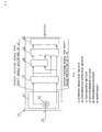
- FIG. 1 is a block diagram of a rotational angle sensor according to the present invention.
- a rotational angle sensor 10 includes a position detection section 11, a synchronous detection section 12, a calculation section 13, a resolver-digital (R/D) conversion section 14, and a synthesizing section 15.
- the rotational angle sensor 10 has a housing for accommodating these sections, from the position detection section 11 to the synthesizing section 15. Although the housing preferably assumes a sealed structure, the housing may assume an open structure in which one end of the housing is opened for assembly with a casing of counterpart equipment to which an input shaft 16 is connected.
- the synchronous detection section 12, the calculation section 13, the resolver-digital (R/D) conversion section 14, and the synthesizing section 15 are mounted on a circuit board as needed.
- these sections are integrated into an IC (integrated circuit) as needed.
- the circuit board which carries components of these sections is disposed within the housing. Further, when necessary, the components on the circuit board are shielded so as to prevent noise from affecting detection signals from the position detection section 11.
- the position detection section 11 is formed by a variable-reluctance (VR) resolver 17, which has the input shaft 16, and has a special configuration to be described later.
- VR variable-reluctance
- the synchronous detection section 12 performs synchronous detection for signal voltages output from output coils of the VR resolver 17 so as to remove excitation frequency components from the signal voltages, and outputs a signal voltage for a shaft angle multiplier of nX (hereinafter referred to as an nX signal voltage) and a signal voltage for a shaft angle multiplier of (n-1)X (hereinafter referred to as an (n-1)X signal voltage), which contain no excitation frequency component.
- the calculation section 13 calculates a sinusoidal signal voltage which includes a sin ⁇ component for a shaft angle multiplier of 1X, in accordance with addition theorem in relation to sine (sin), which is a trigonometric function, on the basis of the nX signal voltage and the (n-1)X signal voltage.
- the calculation section 13 calculates a sinusoidal signal voltage which includes a sin(2n-1) ⁇ component for a shaft angle multiplier of (2n-1)X, in accordance with addition theorem in relation to sine, which is a trigonometric function, on the basis of the nX signal voltage and the (n-1)X signal voltage.
- the resolver-digital (R/D) conversion section 14 converts to digital signals the signal voltages output from the synchronous detection section 12 and the calculation section 13.
- the synthesizing section 15 performs the following calculation on the basis of the digital signals output from the resolver-digital (R/D) conversion section 14.
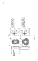
- FIG. 2 is a schematic diagram showing the coil configuration of a resolver according to the present invention.
- FIG. 3 is a schematic cross-sectional view of the resolver of FIG. 2, wherein section (a) shows a transverse cross section, and section (b) shows a cross section taken along a line A-A' in section (a).
- the position detection section 11 includes a stator 19 and a rotor 20.
- the rotor 20 includes two rotor portions; i.e., a 2X output rotor portion 29 having a salient pole shape for a shaft angle multiplier of 2X, and a 3X output rotor portion 30 having a salient pole shape for a shaft angle multiplier of 3X.
- the stator 19 has two excitation coils 21 and 22, and two output coil sets 27 and 28.
- the output coil set 27 outputs a voltage for the shaft angle multiplier of 2X
- the output coil set 28 outputs a voltage for the shaft angle multiplier of 3X.
- the shaft angle multiplier of 2X corresponds to the shaft angle multiplier of (n-1)
- the shaft angle multiplier of 3X corresponds to the shaft angle multiplier of n.
- the 2X output rotor portion 29, which has no coil, is formed of silicon steel and has two plate-shaped salient poles disposed symmetrically with respect to the center axis.
- the 3X output rotor portion 30, which has no coil, is formed of silicon steel and has three plate-shaped salient poles disposed at uniform angular intervals about the center axis.
- the 2X output rotor portion 29 and the 3X output rotor portion 30 are superposed on each other along the axial direction to thereby complete the rotor 20.
- the 2X output rotor portion 29 and the 3X output rotor portion 30 may be formed integrally; i.e., as a single member.
- the stator 19 has magnetic poles 31, 33, 35, and 37 for the shaft angle multiplier of 2X, which are disposed at intervals of 90 degrees (mechanical angle), and magnetic poles 31, 32, 34, 35, 36, and 38 for the shaft angle multiplier of 3X, which are disposed at intervals of 60 degrees (mechanical angle). Since the magnetic poles 31 and 35 are commonly used for the shaft angle multiplier of 2X and the shaft angle multiplier of 3X, in total, eight magnetic poles are formed. However, magnetic poles totaling more than eight; for example, twelve magnetic poles, may be provided.
- Each coil set includes a sin output coil and a cos output coil wound at angular positions separated each other by 90 degrees (electrical angle).
- the output coil set 27 for the shaft angle multiplier of 2X provided on the magnetic poles 31, 33, 35, and 37 of the stator 19 are combined with the 2X output rotor portion 29.
- the output coil set 27 includes a sin output coil 23 (consisting of coil segments 23-1 and 23-2) and a cos output coil 24 (consisting of coil segments 24-1 and 24-2), which are wound around the corresponding magnetic poles, while the magnetic pole 31 (zero point P) is used as a reference, and a phase difference of 90 degrees (electrical angle) is provided therebetween.
- the output coil set 27 for the shaft angle multiplier of 2X outputs voltages represented by the following equations.
- V1' Asin ⁇ t ⁇ sin2 ⁇
- V2' Asin ⁇ t ⁇ cos2 ⁇
- the output coil set 28 for the shaft angle multiplier of 3X provided on the magnetic poles 31, 32, 34, 35, 36, and 38 of the stator 19 are combined with the 3X output rotor portion 30.
- the output coil set 28 includes a sin output coil 25 (consisting of coil segments 25-1, 25-2, and 25-3) and a cos output coil 26 (consisting of coil segments 26-1, 26-2, and 26-3), which are wound around the corresponding magnetic poles, while the magnetic pole 31 (zero point P) is used as a reference, and a phase difference of 90 degrees (electrical angle) is provided therebetween.
- the output coil set 28 for the shaft angle multiplier of 3X outputs voltages represented by the following equations.
- V3' Bsin ⁇ t ⁇ sin3 ⁇
- V4' Bsin ⁇ t ⁇ cos3 ⁇
- the rotational angle sensor is designed to generate such favorable signals, and utilizes the signals so as to produce an output signal for the shaft angle multiplier of 1X; i.e., a sinusoidal wave signal whose period is 360 degrees (mechanical angle). That is, such a sinusoidal wave signal is produced from an nX resolver output signal and an (n-1)X resolver output signal, where n is an arbitrary integer of 3 or greater.
- the R/D conversion section 14 receives the output voltage signal for the shaft angle multiplier of 1X output from the calculation section 13 and the nX resolver output signal or the (n-1)X resolver output signal output from the synchronous detection section 12 and, at each sampling time, converts them to R/D conversion output data values (digital signals).
- the synthesizing section 15 obtains a triangular wave characteristic (mechanical angle-electrical angle characteristic, referred to as a "single-pole digital signal characteristic) which has a single peak for a rotational angle of 360 degrees (mechanical angle), from the R/D conversion output data value for the shaft angle multiplier of 1X. Further, the synthesizing section 15 obtains a triangular wave characteristic (mechanical angle-electrical angle characteristic, referred to as a "multi-pole digital signal characteristic) which has n or (n-1) peaks for a rotational angle of 360 degrees (mechanical angle), from the R/D conversion output data value for the shaft angle multiplier of nX or the shaft angle multiplier of (n-1).
- the synthesizing section 15 obtains a corresponding pole on the multi-pole digital signal characteristic from the R/D conversion output data value of the 1X resolver actually measured on the basis of the single-pole digital signal characteristic, and then obtains an angle (mechanical angle) from actually measured R/D conversion output data value of the nX resolver signal or (n-1)x resolver signal.
- the calculation section 13 obtains the 1X resolver signal by obtaining Asin ⁇ as described in the first embodiment, and further, performs the following calculation while using the output of the synchronous detection section 12 in the first embodiment.
- the calculation section 13 converts the calculation result; i.e., A 2 sin5 ⁇ , to Asin5 ⁇ having the initial amplitude, and outputs Asin5 ⁇ .
- a resolver signal for the shaft angle multiplier of 5X a continuous voltage signal whose period is 360 degrees (mechanical angle) and which consists of 5 triangular wave segments whose period is 360/5 degrees.
- the R/D conversion section 14 receives the output voltage signal for the shaft angle multiplier of 1X and the output voltage signal for the shaft angle multiplier of 5X output from the calculation section 13 and, at each sampling time, converts them to R/D conversion output data values (digital signals).
- the R/D conversion section 14 produces high-accuracy digital signals by making use of signals which are produced on the basis of the knowledge that provision of a plurality of salient portions enables generation of signals which are hardly affected by eccentricity of the center.
- the synthesizing section 15 obtains a triangular wave characteristic (a mechanical angle-electrical angle characteristic, referred to as "single-pole digital signal characteristic) which has a single peak for a rotational angle of 360 degrees (mechanical angle), from the R/D conversion output data value for the shaft angle multiplier of 1X. Further, the synthesizing section 15 obtains a triangular wave characteristic (a mechanical angle-electrical angle characteristic, referred to as "multi-pole digital signal characteristic) which has 5 peaks (i.e., (2n-1) peaks) for a rotational angle of 360 degrees (mechanical angle), from the R/D conversion output data value for the shaft angle multiplier of 5X (i.e., the shaft angle multiplier of (2n-1))X.
- a triangular wave characteristic a mechanical angle-electrical angle characteristic, referred to as "single-pole digital signal characteristic
- multi-pole digital signal characteristic which has 5 peaks (i.e., (2n-1) peaks) for a rotational angle of 360 degrees (
- the synthesizing section 15 obtains a corresponding pole on the multi-pole digital signal characteristic from the R/D conversion output data value of the 1X resolver signal actually measured on the basis of the single-pole digital signal characteristic, and then obtains an angle (mechanical angle) from actually measured R/D conversion output data value of the (2n-1)X resolver signal.
- the above-described configuration enables production, from the R/D conversion signal, of a triangular wave signal which has a short period for the shaft angle multiplier of (2n-1)X, which signal cannot be produced by means of the salient poles of the nX resolver portion or the (n-1)X resolver portion.
- the slope of the triangular wave signal becomes steep, so that even when the detected electrical angle signals vary to some degree because of eccentricity, measured mechanical angle hardly changes, whereby an angle corresponding to an absolute position can be accurately measured.
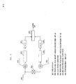
- FIG. 4 is a view showing another example of the rotor of the present invention.
- the rotor is formed of a rotor portion having salient poles for the shaft angle multiplier of 2X and a rotor portion having salient poles for the shaft angle multiplier of 3X, which are superposed on each other.
- salient poles for the shaft angle multiplier of 2X and salient poles for the shaft angle multiplier of 3X are formed on a single annular plate such that the salient poles for the shaft angle multiplier of 2X are located on one side of a plane including the center axis, and the salient poles for the shaft angle multiplier of 3X are located on the other side of the plane.
- the salient poles for the shaft angle multiplier of 2X are formed in such a manner that a single complete salient pole is formed at the center and a half salient pole is formed on the left and right sides of the complete salient pole.
- the numbers of salient poles formed on the opposite sides of the plane may be set arbitrarily, so long as the difference between the numbers is 1.
- the rotor of the third embodiment can be used in combination with the stator of FIG. 1.
- the present invention can be applied to various apparatus, such as resolvers, rotation sensors, angle measurement devices, in which two or more sets of salient poles are provided so as to output a voltage signal for the shaft angle multiplier of nX and a voltage signal for the shaft angle multiplier of (n-1)X, and a voltage signal for the shaft angle multiplier of 1X is obtained from these voltage signals on the basis of the cosine theorem.
- the number of salient poles in one group and the number of salient poles in the other group may be determined freely, so long as the first number is n and the second number is n-1, where n is an arbitrary integer of 3 or greater.
Landscapes
- Physics & Mathematics (AREA)
- General Physics & Mathematics (AREA)
- Transmission And Conversion Of Sensor Element Output (AREA)
- Measurement Of Length, Angles, Or The Like Using Electric Or Magnetic Means (AREA)
Applications Claiming Priority (2)
| Application Number | Priority Date | Filing Date | Title |
|---|---|---|---|
| JP2004093763 | 2004-03-26 | ||
| JP2004093763A JP4142607B2 (ja) | 2004-03-26 | 2004-03-26 | バリアブルリラクタンスレゾルバ |
Publications (2)
| Publication Number | Publication Date |
|---|---|
| EP1580533A2 true EP1580533A2 (de) | 2005-09-28 |
| EP1580533A3 EP1580533A3 (de) | 2007-03-28 |
Family
ID=34858527
Family Applications (1)
| Application Number | Title | Priority Date | Filing Date |
|---|---|---|---|
| EP05003804A Withdrawn EP1580533A3 (de) | 2004-03-26 | 2005-02-22 | Resolver mit veränderlicher Reluktanz und darauf basierender Winkelsensor |
Country Status (3)
| Country | Link |
|---|---|
| US (1) | US7088025B2 (de) |
| EP (1) | EP1580533A3 (de) |
| JP (1) | JP4142607B2 (de) |
Cited By (5)
| Publication number | Priority date | Publication date | Assignee | Title |
|---|---|---|---|---|
| EP2653836A1 (de) * | 2012-04-19 | 2013-10-23 | ABB Research Ltd. | Vorrichtung und Verfahren zur Überwachung einer Exzentrizität oder eines kleinsten Luftspalts einer elektrischen drehenden Maschine |
| TWI489089B (zh) * | 2013-10-07 | 2015-06-21 | Hiwin Mikrosystem Corp | Absolute angle analysis device |
| EP3218668A4 (de) * | 2014-09-25 | 2018-09-12 | Texas Instruments Incorporated | Mehrstufige rotierende drehgeber mit induktiven sensoren |
| US10927896B2 (en) | 2019-07-15 | 2021-02-23 | Schaeffler Tehnologies AG & Co. KG | Motor assembly and method of assembling motor |
| US11606013B2 (en) | 2020-02-19 | 2023-03-14 | Schaeffler Technologies AG & Co. KG | Resolver integration kit for variable reluctance resolver |
Families Citing this family (18)
| Publication number | Priority date | Publication date | Assignee | Title |
|---|---|---|---|---|
| US20080189072A1 (en) * | 2007-02-01 | 2008-08-07 | Nescom Inc. | High resolution encoder within a swivel |
| DE102009061032A1 (de) * | 2009-05-15 | 2010-11-18 | Tyco Electronics Belgium Ec Bvba | Magnetoelektronischer Winkelsensor, insbesondere Reluktanzresolver |
| JP5778976B2 (ja) * | 2011-04-28 | 2015-09-16 | ミネベア株式会社 | Vr型レゾルバおよび角度検出システム |
| US9627936B2 (en) * | 2011-12-23 | 2017-04-18 | Mitsubishi Electric Corporation | Permanent magnet motor |
| RU2529825C1 (ru) * | 2013-03-04 | 2014-09-27 | Федеральное государственное бюджетное образовательное учреждение высшего профессионального образования "Саратовский государственный аграрный университет имени Н.И. Вавилова" | Многоступенчатый датчик угла |
| JP6009493B2 (ja) * | 2014-05-21 | 2016-10-19 | ミネベア株式会社 | レゾルバ |
| US10480961B2 (en) | 2017-01-31 | 2019-11-19 | Rockwell Automation Technologies, Inc. | Hybrid encoder system for position determination |
| JP7076962B2 (ja) * | 2017-07-31 | 2022-05-30 | マブチモーター株式会社 | レゾルバ及びモータ |
| JP2019124514A (ja) * | 2018-01-15 | 2019-07-25 | 多摩川精機株式会社 | 多極レゾルバ |
| US10084472B1 (en) * | 2018-03-01 | 2018-09-25 | Tamagawa Seiki Co., Ltd. | Phase modulation-type redundant two-phase-output resolver and signal output method thereof |
| JP7026827B2 (ja) * | 2019-01-25 | 2022-02-28 | 三菱電機株式会社 | 角度検出装置 |
| WO2021195118A1 (en) | 2020-03-23 | 2021-09-30 | Moog Inc. | Variable reluctance resolver using surface mounted inductors and/or transformers |
| JP7314426B2 (ja) * | 2020-12-11 | 2023-07-25 | マブチモーター株式会社 | レゾルバ |
| US11601077B1 (en) | 2021-09-30 | 2023-03-07 | Rolls-Royce Corporation | Technologies for redundant shaft information feedback in electric machine systems including a resolver |
| US11646682B2 (en) | 2021-09-30 | 2023-05-09 | Rolls-Royce Corporation | Technologies for redundant shaft information feedback in multi-machine drive systems with multiple resolvers |
| US11646685B2 (en) | 2021-09-30 | 2023-05-09 | Rolls-Royce Corporation | Technologies for redundant shaft information feedback in electric machine systems having multiple resolvers |
| CN115265413A (zh) * | 2022-09-01 | 2022-11-01 | 北京航空航天大学 | 一种用于微小推力测量和卫星姿轨控仿真的角位移测量方法 |
| JPWO2024117110A1 (de) * | 2022-11-30 | 2024-06-06 |
Family Cites Families (38)
| Publication number | Priority date | Publication date | Assignee | Title |
|---|---|---|---|---|
| US3688306A (en) * | 1970-03-18 | 1972-08-29 | Nippon Denso Co | Digital type rotational angle detector |
| US3705343A (en) * | 1971-04-26 | 1972-12-05 | William L Ringland | Three phase rotary inductor vector adder |
| JPS5546862A (en) * | 1978-09-25 | 1980-04-02 | Okuma Mach Works Ltd | Multipolar resolver |
| US4612503A (en) * | 1980-10-21 | 1986-09-16 | Kabushiki Kaisha S G | Rotation speed detection device having a rotation angle detector of inductive type |
| JPH0630556B2 (ja) * | 1984-01-20 | 1994-04-20 | 東芝機械株式会社 | 回転位置検出器組込型モ−タ |
| US4631510A (en) * | 1985-09-03 | 1986-12-23 | Powerton, Division Of Contraves Goerz Corporation | Harmonically graded airgap reluctance-type rotating electric resolver |
| US4968516A (en) | 1989-07-24 | 1990-11-06 | Thompson Neal W | Method and apparatus for cooking foodstuffs using auxiliary steam |
| FR2679026B1 (fr) * | 1991-07-11 | 1993-09-24 | Alsthom Gec | Dispositif pour la mesure de la position angulaire d'un rotor par rapport a un stator. |
| US5763976A (en) * | 1993-12-15 | 1998-06-09 | Parker-Hannifin Corp. | Stator wound resolver with staggered rotor |
| US5444368A (en) * | 1994-01-10 | 1995-08-22 | H. Magnetic Corp. | Differential reactance permanent magnet position transducer |
| US5469055A (en) * | 1994-05-04 | 1995-11-21 | Honeywell Inc. | Engine shaft with integrally formed complementary targets |
| US5570016A (en) * | 1994-06-01 | 1996-10-29 | General Motors Corporation | Method and apparatus for detecting crankshaft angular position |
| US5754042A (en) * | 1994-06-20 | 1998-05-19 | General Motors Corporation | Magnetoresistive encoder for tracking the angular position of a rotating ferromagnetic target wheel |
| US5948040A (en) * | 1994-06-24 | 1999-09-07 | Delorme Publishing Co. | Travel reservation information and planning system |
| US6460036B1 (en) * | 1994-11-29 | 2002-10-01 | Pinpoint Incorporated | System and method for providing customized electronic newspapers and target advertisements |
| JP3138606B2 (ja) * | 1995-01-06 | 2001-02-26 | 多摩川精機株式会社 | 角度検出器 |
| US5870719A (en) * | 1996-07-03 | 1999-02-09 | Sun Microsystems, Inc. | Platform-independent, usage-independent, and access-independent distributed quote configuraton system |
| US6076080A (en) * | 1997-11-04 | 2000-06-13 | The Standard Register Company | Forms order entry system |
| US6078897A (en) * | 1998-02-02 | 2000-06-20 | Intraware, Inc. | Method and apparatus for optimizing orders for goods or services to increase a discount |
| GB2341708B (en) * | 1998-09-18 | 2002-03-27 | Ibm | Routing system |
| JP2000316266A (ja) * | 1999-04-28 | 2000-11-14 | Oriental Motor Co Ltd | 可変磁気抵抗型位置検出器 |
| US6064981A (en) * | 1999-06-17 | 2000-05-16 | Barni; Neil A. | Method for online display and negotiation of cargo rates |
| JP2001183169A (ja) * | 1999-12-24 | 2001-07-06 | Oriental Motor Co Ltd | 位置検出装置 |
| JP2001250188A (ja) * | 2000-03-06 | 2001-09-14 | Sony Corp | 半導体装置の輸送方法および半導体装置の輸送経路選択方法 |
| US7774284B2 (en) * | 2000-03-27 | 2010-08-10 | Stamps.Com Inc. | Apparatus, systems and methods for online, multi-parcel, multi-carrier, multi-service enterprise parcel shipping management |
| US20010037281A1 (en) * | 2000-04-13 | 2001-11-01 | Jason French | Request for quote (RFQ) system and method |
| US6552453B2 (en) * | 2000-05-23 | 2003-04-22 | Japan Servo Co., Ltd. | Magnetic pole position detector for an electric motor |
| US20020019759A1 (en) * | 2000-06-16 | 2002-02-14 | Sundararajan Arunapuram | Transportation planning, execution, and freight payments managers and related methods |
| US7184973B2 (en) * | 2000-07-11 | 2007-02-27 | United Parcel Service Of America, Inc. | Method and apparatus for communicating order entries in a network environment |
| US7035856B1 (en) * | 2000-09-28 | 2006-04-25 | Nobuyoshi Morimoto | System and method for tracking and routing shipped items |
| US20020103653A1 (en) * | 2000-12-01 | 2002-08-01 | Stephen Huxter | System and method for facilitating receipt and collection of goods ordered from online retailers |
| US20030018513A1 (en) * | 2001-04-13 | 2003-01-23 | Hoffman George Harry | System, method and computer program product for benchmarking in a supply chain management framework |
| US20030023567A1 (en) * | 2001-07-24 | 2003-01-30 | Berkovitz Joseph H. | Method and system for dynamic pricing |
| US20030040944A1 (en) * | 2001-08-22 | 2003-02-27 | Hileman Ryan M. | On-demand transportation system |
| US6970855B2 (en) * | 2002-01-29 | 2005-11-29 | Pitney Bowes Inc. | Method and system for enterprise-level unassisted customer shipping |
| US6871137B2 (en) * | 2003-02-05 | 2005-03-22 | Gannett Fleming, Inc. | Intelligent road and rail information systems and methods |
| JP4034690B2 (ja) * | 2003-04-28 | 2008-01-16 | ミネベア株式会社 | 2重化バリアブルリラクタンスレゾルバおよびそれを用いた複速度レゾルバシステム |
| JP4158858B2 (ja) * | 2003-12-04 | 2008-10-01 | 多摩川精機株式会社 | 回転角度検出器 |
-
2004
- 2004-03-26 JP JP2004093763A patent/JP4142607B2/ja not_active Expired - Fee Related
-
2005
- 2005-02-18 US US11/060,405 patent/US7088025B2/en not_active Expired - Fee Related
- 2005-02-22 EP EP05003804A patent/EP1580533A3/de not_active Withdrawn
Cited By (7)
| Publication number | Priority date | Publication date | Assignee | Title |
|---|---|---|---|---|
| EP2653836A1 (de) * | 2012-04-19 | 2013-10-23 | ABB Research Ltd. | Vorrichtung und Verfahren zur Überwachung einer Exzentrizität oder eines kleinsten Luftspalts einer elektrischen drehenden Maschine |
| WO2013156363A1 (en) * | 2012-04-19 | 2013-10-24 | Abb Research Ltd | Device and method for monitoring an eccentricity or a smallest air gap of a rotating electric machine |
| TWI489089B (zh) * | 2013-10-07 | 2015-06-21 | Hiwin Mikrosystem Corp | Absolute angle analysis device |
| EP3218668A4 (de) * | 2014-09-25 | 2018-09-12 | Texas Instruments Incorporated | Mehrstufige rotierende drehgeber mit induktiven sensoren |
| EP4148373A3 (de) * | 2014-09-25 | 2023-05-24 | Texas Instruments Incorporated | Mehrstufige rotierende drehgeber mit induktiven sensoren |
| US10927896B2 (en) | 2019-07-15 | 2021-02-23 | Schaeffler Tehnologies AG & Co. KG | Motor assembly and method of assembling motor |
| US11606013B2 (en) | 2020-02-19 | 2023-03-14 | Schaeffler Technologies AG & Co. KG | Resolver integration kit for variable reluctance resolver |
Also Published As
| Publication number | Publication date |
|---|---|
| EP1580533A3 (de) | 2007-03-28 |
| US7088025B2 (en) | 2006-08-08 |
| JP4142607B2 (ja) | 2008-09-03 |
| JP2005283165A (ja) | 2005-10-13 |
| US20050212511A1 (en) | 2005-09-29 |
Similar Documents
| Publication | Publication Date | Title |
|---|---|---|
| EP1580533A2 (de) | Resolver mit veränderlicher Reluktanz und darauf basierender Winkelsensor | |
| US6707291B2 (en) | Self-induction-type position detector device for detecting object position | |
| EP1046884B1 (de) | Positionssensor | |
| US5189353A (en) | Resolver system | |
| JP2558159B2 (ja) | 二相信号発生装置及び二相信号発生方法 | |
| US6552666B1 (en) | Phase difference detection device and method for a position detector | |
| US6958602B2 (en) | High-accuracy 1X variable-reluctance resolver | |
| JP2013152251A (ja) | 回転型位置検出装置 | |
| US5933106A (en) | Encoder signal analysis system for high-resolution position measurement | |
| JPS6258445B2 (de) | ||
| Attaianese et al. | A low cost resolver-to-digital converter | |
| JP2001183169A (ja) | 位置検出装置 | |
| JP2004309177A (ja) | トルクセンサ | |
| EP1054238B1 (de) | Verfahren und Gerät zur Messung der Position unter Verwendung von phasenverschobenen Signalen | |
| WO2006054357A1 (ja) | 相対回転位置検出装置 | |
| EP1016852B1 (de) | Positionssensor | |
| JP3708093B2 (ja) | モータのサーボ制御システムおよびモータの速度制御に利用されるr/dコンバータ | |
| US7119536B2 (en) | Two-resolver deviation angle detector having serially connected output windings | |
| US20110187356A1 (en) | Resolver unit | |
| JPH0212014A (ja) | アブソリュート位置検出器及びその検出回路 | |
| JPH07181060A (ja) | アブソリュートエンコーダ | |
| JPH09318304A (ja) | 位置検出装置 | |
| RU2193794C2 (ru) | Преобразователь параметр - код | |
| JPH0356818A (ja) | 回転角度検出装置 | |
| CN102128585A (zh) | 角度解析装置 |
Legal Events
| Date | Code | Title | Description |
|---|---|---|---|
| PUAI | Public reference made under article 153(3) epc to a published international application that has entered the european phase |
Free format text: ORIGINAL CODE: 0009012 |
|
| AK | Designated contracting states |
Kind code of ref document: A2 Designated state(s): AT BE BG CH CY CZ DE DK EE ES FI FR GB GR HU IE IS IT LI LT LU MC NL PL PT RO SE SI SK TR |
|
| AX | Request for extension of the european patent |
Extension state: AL BA HR LV MK YU |
|
| PUAL | Search report despatched |
Free format text: ORIGINAL CODE: 0009013 |
|
| AK | Designated contracting states |
Kind code of ref document: A3 Designated state(s): AT BE BG CH CY CZ DE DK EE ES FI FR GB GR HU IE IS IT LI LT LU MC NL PL PT RO SE SI SK TR |
|
| AX | Request for extension of the european patent |
Extension state: AL BA HR LV MK YU |
|
| 17P | Request for examination filed |
Effective date: 20070418 |
|
| 17Q | First examination report despatched |
Effective date: 20070530 |
|
| AKX | Designation fees paid |
Designated state(s): DE FR GB IT |
|
| STAA | Information on the status of an ep patent application or granted ep patent |
Free format text: STATUS: THE APPLICATION IS DEEMED TO BE WITHDRAWN |
|
| 18D | Application deemed to be withdrawn |
Effective date: 20090901 |