EP1580489B1 - Unité pour installation de chauffage compacte - Google Patents
Unité pour installation de chauffage compacte Download PDFInfo
- Publication number
- EP1580489B1 EP1580489B1 EP04006831A EP04006831A EP1580489B1 EP 1580489 B1 EP1580489 B1 EP 1580489B1 EP 04006831 A EP04006831 A EP 04006831A EP 04006831 A EP04006831 A EP 04006831A EP 1580489 B1 EP1580489 B1 EP 1580489B1
- Authority
- EP
- European Patent Office
- Prior art keywords
- valve housing
- housing
- pump
- pump housing
- construction unit
- Prior art date
- Legal status (The legal status is an assumption and is not a legal conclusion. Google has not performed a legal analysis and makes no representation as to the accuracy of the status listed.)
- Expired - Lifetime
Links
- 238000010438 heat treatment Methods 0.000 title claims abstract description 84
- 238000009434 installation Methods 0.000 title claims description 9
- 238000010276 construction Methods 0.000 claims abstract description 22
- XLYOFNOQVPJJNP-UHFFFAOYSA-N water Substances O XLYOFNOQVPJJNP-UHFFFAOYSA-N 0.000 claims description 20
- 238000001746 injection moulding Methods 0.000 claims description 14
- 230000002093 peripheral effect Effects 0.000 claims description 4
- 238000007789 sealing Methods 0.000 claims 1
- 208000028659 discharge Diseases 0.000 description 11
- 238000004519 manufacturing process Methods 0.000 description 6
- 238000004891 communication Methods 0.000 description 4
- 238000005192 partition Methods 0.000 description 4
- 239000012530 fluid Substances 0.000 description 3
- 230000007704 transition Effects 0.000 description 3
- 230000003014 reinforcing effect Effects 0.000 description 2
- 230000004323 axial length Effects 0.000 description 1
- 230000015572 biosynthetic process Effects 0.000 description 1
- 230000001914 calming effect Effects 0.000 description 1
- 230000001419 dependent effect Effects 0.000 description 1
- 230000002349 favourable effect Effects 0.000 description 1
- 239000008236 heating water Substances 0.000 description 1
- 208000012313 wound discharge Diseases 0.000 description 1
Images


Classifications
-
- F—MECHANICAL ENGINEERING; LIGHTING; HEATING; WEAPONS; BLASTING
- F24—HEATING; RANGES; VENTILATING
- F24H—FLUID HEATERS, e.g. WATER OR AIR HEATERS, HAVING HEAT-GENERATING MEANS, e.g. HEAT PUMPS, IN GENERAL
- F24H9/00—Details
- F24H9/14—Arrangements for connecting different sections, e.g. in water heaters
- F24H9/142—Connecting hydraulic components
- F24H9/144—Valve seats, piping and heat exchanger connections integrated into a one-piece hydraulic unit
-
- F—MECHANICAL ENGINEERING; LIGHTING; HEATING; WEAPONS; BLASTING
- F24—HEATING; RANGES; VENTILATING
- F24H—FLUID HEATERS, e.g. WATER OR AIR HEATERS, HAVING HEAT-GENERATING MEANS, e.g. HEAT PUMPS, IN GENERAL
- F24H1/00—Water heaters, e.g. boilers, continuous-flow heaters or water-storage heaters
- F24H1/48—Water heaters for central heating incorporating heaters for domestic water
Definitions
- the invention relates to a structural unit for a compact heating system, in particular for a gas boiler with two heating circuits, one for space heating and one for hot water.
- Building units of this type are now increasingly installed in compact heating systems, especially in gas heating. They include in addition to a centrifugal pump unit usually other components, such as air separator, safety valve, changeover valve and the like. They are called a structural unit, d. H. designed as a mounting and mounting unit, so that a simple and space-saving arrangement of all major units within the heating system is guaranteed. In addition, such a unit is easy to assemble and maintain, as access to the otherwise tight installation space must be ensured only at a few central locations and otherwise the unit can be completely replaced and factory or elsewhere overhauled by the specialist and recycled.
- EP 0874 201 A2 is such a unit for a compact heating system known.
- the unit has as essential elements a centrifugal pump and a switching valve, which can switch between two heating circuits, one for domestic water heating and one for space heating.
- the switching valve is arranged in a valve housing, which is designed as a separate component, which is connected to a suction-side connection of the pump at the rear of the pump housing.
- EP 0 394 140 A1 discloses a circulation pump with an adjoining valve housing, in which a valve for switching between two inlets is arranged.
- the valve housing connects at the axial end of the end face of the pump housing, so that the axial length of the entire unit is extended. This leads to a relatively large aggregate.
- the assembly according to the invention is intended for a compact heating system with two heating circuits, one for space heating and one for domestic water heating.
- the two heating circuits are connected by a switching valve as needed with a primary circuit of the heating system, in which a primary heat exchanger is arranged to heat the water in the heating circuit.
- the systems are usually operated so that in the basic state of the heating circuit for space heating is heated and the heating circuit for domestic water heating only when requested by heated hot water, for example via a pressure switch is activated. At this moment, the first heating circuit for the room heating is interrupted.
- This is one Switching provided, which is arranged in a valve housing, which is a part of the assembly.
- the unit has a circulating pump, which circulates the water or fluid in the heating circuits, in particular pumps the water through the primary circuit.
- the circulation pump is arranged in a pump housing.
- the pump housing and the valve housing are at least partially formed integrally with one another.
- the valve housing is attached to the pump housing or in such a way This integrates that the valve body cuts the pump housing.
- a connection between the valve housing and the pump housing is thus created. That is, the interior of the valve housing and the interior of the pump housing are in the intersection of the housing in communication so that a flow passage between the two housings is created.
- fluid can flow directly from the valve housing into the pump housing and from there to the circulation pump, or vice versa.
- valve and pump housing a very compact unit is created. Furthermore, the one-piece design of pump housing and valve housing reduces the assembly effort. Thus, at least a part of the pump housing is integral with at least a part of the valve housing, preferably made of plastic by injection molding. This allows a very cost-effective production.
- the flow passage connects the interior of the valve housing with the suction side of the circulation pump.
- the valve or switching valve which is usually formed in such compact heating systems as 2/3-way valve is preferably arranged in the return of the heating circuits, ie by switching the switching element in the valve is either the return of the heating circuit for space heating or the return of the heating circuit for DHW heating connected to the suction side of the pump.
- the pressure side of the pump is in this case connected to the primary circuit, so that the pump delivers the water flowing through one of the two heating circuits to the primary heat exchanger, where it is heated.
- the valve housing preferably intersects a calming space on the suction side of the pump, which is intended to calm the flow before entering the circulation pump.
- an air separator can be arranged in this room.
- valve housing is substantially cylindrical, in particular circular cylindrical, formed, wherein it intersects the pump housing in its peripheral region. This means that the pump housing is attached tangentially to the valve housing and cuts it in the region of a circular segment or segment,
- the pump housing is preferably cylindrical, in particular circular-cylindrical, wherein one end face is closed and the valve housing intersects the pump housing in the region of this, preferably rear end face. That is, the pump housing engages with its end face in a partial region of the space defined by the circumference of the valve housing.
- the pump housing preferably extends in the installed position horizontally from the front to the back of the assembly, the pump being inserted from the front into the pump housing.
- the valve housing is preferably formed on the rear side of the pump housing, wherein it cuts the space defined by the pump housing.
- the longitudinal axes of the pump housing and the valve housing are normal and preferably spaced from each other.
- the longitudinal axis of the pump housing preferably extends in the installation position of the assembly horizontally from front to back, while the longitudinal axis of the valve housing extends vertically.
- the axes are more preferably spaced apart, d. H. the valve housing is offset radially, eccentrically preferably arranged on the end face of the pump housing.
- the valve housing preferably has two connecting pieces for connection to the two heating circuits, wherein, starting from the connecting pieces, a respective pipe section extends into the interior of the valve housing, the free ends of the two pipe sections from one another are spaced, opposed to each other and formed as valve seats. Between the free ends of the pipe sections, the switching member is arranged, which abuts depending on the switching position on one of the valve seat designed as ends of the pipe sections and thus shoots the corresponding pipe section. At the same time, the respective other pipe section is opened at its end, which is designed as a valve seat and faces the switching element, to the surrounding space in the interior of the valve housing, so that a flow path into the interior of the pump housing is released via this. In this way, a flow path between one of the two heating circuit and the interior of the pump housing, preferably the suction side of the pump, can be selectively switched.
- the two pipe sections are preferably formed in alignment with each other, so that a compact valve arrangement is provided.
- a free space is formed, which is in the interface between the pump housing and the valve housing with the interior of the pump housing in communication to form the flow passage from the valve housing to the pump housing.
- the pipe sections are arranged concentrically with the valve housing in its interior, so that the outer wall of the pipe sections is arranged radially spaced from the inner wall of the valve housing and an annular clearance is formed, which surrounds the pipe sections on its outer side.
- the valve housing thereby cuts the pump housing in the region of this free space so that a connection of this free space to the interior of the pump housing, preferably to the suction side of the pump, is created.
- At least one of the two pipe sections extends in the direction of the longitudinal axis of the valve housing.
- This enables a slim and compact valve body.
- the straight configuration and coaxial arrangement of pipe sections and valve housing allows the pipe sections and the valve housing to be formed by means of drawing cores, so that lost cores can be dispensed with during injection molding, whereby the production costs are reduced.
- a first connecting piece is preferably formed on a first end side of the valve housing and preferably extends in the longitudinal direction of the valve housing. With this first connecting piece one of the two heating circuits, preferably connected for the space heating.
- the first end face is preferably formed open and the connecting piece with the associated first pipe section is designed as an insert, which is sealingly inserted into the open first end side.
- the connecting piece with the first pipe section can then be inserted as a prefabricated extra component in the open end to close it and at the same time to arrange the first pipe section inside the valve housing. This allows a cost-effective production with simple installation.
- a second connection piece is formed on a peripheral surface of the valve housing, preferably near an end face facing away from the first end side.
- This second connection piece is used to connect the valve housing to the second heating circuit, preferably the one for domestic water heating.
- This heating circuit for domestic water heating is formed in particular by a secondary heat exchanger, in which the service water is heated by the fluid or water in the second heating circuit.
- the two connecting pieces are preferably arranged in the region of opposite ends of the valve housing, so that the two pipe sections, starting from the two end sides of the valve housing toward each other and arranged the switching member in the central region of the valve housing between the facing and spaced from each other open ends of the pipe sections is.
- the second connecting piece preferably extends substantially normal to the longitudinal axis of the valve housing and preferably normal to the longitudinal axis of the pump housing.
- the second connection piece preferably also extends normally to the first connection piece.
- a particularly preferred arrangement is that in which the pump housing in the installed position of the assembly extends horizontally from front to back and the valve housing at the rear of the pump housing extends vertically from bottom to top, wherein the second connecting piece normal to the longitudinal axis of the valve housing and the pump housing, d. H. extends in the lateral direction. This allows, for example, that a secondary heat exchanger for domestic water heating can be attached laterally to the valve housing.
- the second connecting piece and the subsequent second pipe section are preferably formed integrally with the valve housing. So these parts can in one operation, for example by injection molding be formed of plastic, whereby the number of required assembly steps is reduced.
- the second connection piece and at least part of the adjoining second pipe section are preferably formed by means of a swivel-pull core by injection molding.
- a pivoting core is arcuately curved and moves along a circular path in the direction of its curvature.
- a connecting piece can be formed, which extends transversely, in particular normal to the subsequent second pipe section, wherein between the pipe section and connecting piece a curved transition region is formed.
- a curved pipe section can be formed with the help of the Schwenkziehkernes so that no lost cores are required.
- the adjoining straight region of the second pipe section, which faces the switching element can be formed by a further, preferably linearly moving, drawing core, which can be pulled out through the open end side of the valve housing.
- the pump housing has a, preferably integrally formed with the pump housing discharge nozzle for connecting a heating circuit, in particular a primary circuit of the heating system.
- the one-piece design of the pressure nozzle with the pump housing also reduces the number of required assembly steps to complete the assembly.
- the discharge nozzle is preferably formed by means of a fferziehkerns injection molding.
- the use of a screwdriver core allows a fluidically favorable curvature of the pressure nozzle to be formed without having to rely on the use of lost cores.
- the fferziehkern is along the Curvature of the formed pressure nozzle in a screwing movement, ie taken in a combined rotational and linear movement of the trained pressure port.
- the first connecting piece of the valve housing extends to a first side, in particular the underside of the assembly
- the discharge nozzle of the pump housing preferably extends opposite to the first side facing away from the second side of the assembly
- the second connection piece of the valve housing preferably extends transversely to the Discharge nozzle and the first connection nozzle.
- This configuration allows in installation position of the unit in a compact heating system, an arrangement in which the discharge nozzle extends upward to a primary heat exchanger arranged above the unit.
- the first connection piece of the valve housing preferably extends downwards d. H. to the bottom of the unit and the compact heating system to which the connection pipes for space heating arrive.
- the second connection piece of the valve housing extends horizontally in the lateral direction to a secondary heat exchanger arranged directly on the unit for heating service water.
- the first and the second connecting piece of the valve housing and the discharge nozzle of the pump housing extend substantially in one plane, so that the overall depth of the compact heating system is kept low.
- the valve housing may be extended at its upper end in the installed position over the flow passage to the pump housing, wherein in the region above the flow passage in the Ventügetude an air separator is arranged.
- the valve housing is extended beyond the open sectional area between the pump housing and valve housing and thus creates a receiving space for the air separator, which arranged there to save space can be without having to enlarge the pump housing.
- the valve housing preferably has a second open end side provided at the upper end, in which the air separator is inserted.
- This open configuration of the second end face also has the advantage that pulling cores can also be removed therefrom so that a simple configuration of the interior of the valve housing is made possible without the use of lost cores.
- the opening on the second end face of the valve housing can be closed by a plug or plug.
- the pump housing may be formed on the suction side of the pump for receiving an air separator.
- the assembly consists essentially of a pump housing 2 and an integrally adjoining valve housing 4.
- a circulating pump 6 is used in the pump housing 2.
- a 2/3-way valve for switching the pump flow between two heating circuits is arranged in the valve housing 4.
- the associated switching element in the interior of the valve housing 4 is actuated by a valve drive 8 in the form of an electric motor.
- the assembly has three connecting pieces 10, 12 and 14.
- the connecting piece 10 is formed as a discharge nozzle on the pump housing 2.
- the discharge nozzle 10 is in communication with the pressure side of the circulation pump 6 and is used for connection to a primary circuit a compact heating system, in which a primary heat exchanger for heating the heating water, for example via a gas burner, is arranged.
- the connecting pieces 12 and 14 are formed on the valve housing 4 and communicate with the arranged in the interior of the valve housing 4 switching member in connection.
- the Anschussstutzen 14 is disposed at the opposite end of the valve housing 4 and extends in the radial lateral direction of the valve housing 4.
- the connecting piece 14 is used for connection to a second heating circuit for domestic water heating. In this second heating circuit, a secondary heat exchanger is arranged in the compact heating system, via which the service water is heated.
- the 2/3-way valve in the valve housing 4 is used for selectively connecting the connecting pieces 12 and 14, ie the two heating circuits connected thereto, with the suction side of the circulation pump 6. This means, depending on the position of the switching element in the interior of the valve housing 4 by actuation of the valve drive 8 becomes that of the circulation pump 6 generated pump current passed through the first heating circuit for space heating or through the second heating circuit for domestic water heating.
- the pump housing 2 and the valve housing 4 are manufactured as a one-piece plastic component by injection molding.
- the pump housing 2 and the valve housing 4 intersect or penetrate each other. That is, the geometric base body defined by pump housing 2 and valve housing 4, in the example shown two cylinders, intersect each other or interlock.
- a flow passage is created in the interior between the pump housing 2 and valve housing 4, which connects the interior of the valve housing 4 with the suction side of the circulation pump 6.
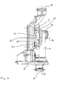
- Fig. 1 The installation position of the unit in a compact heating system is usually as in Fig. 1 shown, ie, the connecting piece 12 is disposed on the underside and the discharge nozzle 10 at the top and the stator housing of the circulation pump 6 is arranged on the front side of the assembly.
- Fig. 2 shows a plan view of the back of the assembly, ie on the closed back of the pump housing. 2
- the pump housing 2 has a substantially cylindrical interior 16 (see Fig. 3-5 ), which, as in Fig. 2 shown formed on the rear end face 17 is closed. From the front end side, the circulation pump 6 is used, as based on Fig. 3 will be explained.
- the valve housing 4 is also substantially cylindrical.
- the longitudinal axis A of the valve housing 4 extends substantially normal and spaced from the longitudinal axis B of the pump housing 2.
- the valve housing 4 in such a way to the rear end side 17 (in FIG Fig. 2 the observer facing end) of the pump housing 2 added that the cylinder contour of the Valve housing 4, the pump housing 2 eccentrically cuts at the end face. That is, the pump housing 2 and valve housing 4 engage each other.
- the pump housing additionally has a number of reinforcing ribs 18 and mounting holes 20.
- Fig. 3 shows a front view of the assembly according to FIGS. 1 and 2 , wherein the circulation pump 6 is removed from the pump housing 2.
- the interior 16 of the pump housing 2 is formed substantially cylindrical for receiving the circulating pump 6.
- a normal to the longitudinal axis B of the pump housing 2 extending partition 21 is arranged, in the interior of which the suction mouth 22 is formed centrally for the circulation pump 6.
- Fig. 4 shows a sectional view of the assembly with reference to the line IV-IV in Fig. 3 , In Fig. 4 It can be seen how the cylindrical valve housing 4 and the cylindrical pump housing 2 intersect at the end face of the pump housing 2.
- the valve housing 4 is attached with a circumferential surface on the end face of the pump housing 2, wherein the valve housing 4 and the pump housing 2 with their outer contours engage each other so that an opening or a flow passage 24 is formed between the two.
- the flow passage 24 connects the interior of the valve housing 4 with the interior 16 of the pump housing 2 and in particular with the suction port 22 for the circulation pump 6 (in Fig. 4 Not shown).
- the outer walls of the pump housing 2 and the valve housing 4 are formed as a one-piece plastic component, so that a simple and cost-effective production is possible.
- Fig. 5 shows a sectional view of the assembly along the line VV in Fig. 3 , In Fig. 5 the structure of the valve housing 4 is explained in more detail.
- the valve housing 4 is formed substantially cylindrical and extends along the longitudinal axis A in the installed position of the assembly in the vertical direction. At the lower end, the valve housing 4 has an opening 26, in which the connecting piece 12 is inserted as an insert. In this case, the connecting piece 12 is sealingly connected to the opening 26.
- a first pipe section 28 extends into the interior of the valve housing 4.
- the tubular section 28 extends concentrically to the longitudinal axis A and spaced from the inner wall of the valve housing 4.
- the free end of the pipe section 28 facing away from the connecting piece 12 forms a first valve seat 30th
- a second pipe section 32 extends into the interior of the valve housing 4.
- the pipe section 32 extends concentrically to the longitudinal axis A and spaced from the inner wall of the valve housing 4.
- the free end the pipe section 32 forms a second valve seat 34.
- the pipe sections 32 and 28 extend in alignment with each other so that the first and second valve seat 30 and 34 are opposed to each other.
- the valve seats 30 and 34 are spaced from each other. Between the valve seats 30 and 34, the switching member 36 is arranged, which is movable by the valve drive 8.
- the switching member 36 can be moved so that it rests sealingly either on the first valve seat 30 or on the second valve seat 34, so either one of the pipe sections 28 and 32 is closed, while the other pipe section at its free end, d. H. in the region of the valve seat 30, 34 to the interior 28 of the valve housing 4 is open.
- the annular clearance 38 is in the interface between the pump housing 2 and the valve housing 4, that is, via the flow passage 24 in communication with the interior 16 of the pump housing 2 and thus the suction port 22 of the circulation pump 6.
- the switching position of the switching element 36 is a connection one of the pipe sections 28 and 30 made via the interior 38 and via the flow passage 24 with the suction side of the pump.
- the two heating circuits of the compact heating system ie the heating circuit for space heating and the heating circuit for hot water heating with the connecting pieces 12 and 14 of the valve housing 4 are connected.
- the terminals of the two heating circuits can be optionally closed at the valve seats 30 and 34, so that always the respective non-sealed connection is connected to the suction side of the pump. In this way, in the 2/3-way valve by movement of the switching member 36 of the pump flow generated by the circulation pump 6 between the two heating circuits, which are connected to the connecting pieces 12 and 14, switched.
- the above-described embodiment of the pump housing 2 and the valve housing 4 has the advantage that it can be formed without using lost cores by injection molding and at the same time the number of required assembly operations is kept low.
- the pump housing 2 and the valve housing 4 are initially formed without the inserted connecting piece 12 and the partition 21. This makes it possible to remove through the opening 26 of the valve housing 4 drawing cores, which the formation of the inner space 38 and the second pipe section 32 inside the Allow valve housing 4. At the same time, a further pulling core can be removed from the interior 16 of the pump housing 2 from the open front side, which defines the interior 16 of the pump housing 2 during injection molding.
- the drawing cores which are defined in the interior 16 of the pump housing 2 and the interior 38 of the valve housing 4 touch each other in the interface between the pump housing 2 and the valve housing 4, so that the flow passage 24 is formed.
- the helically wound discharge nozzle 10 can be formed via a screwdriver core. This allows a streamlined curvature of the pressure nozzle 10 to the interior 16 of the pump housing 2 out. To remove the core, which forms the interior of the pressure nozzle 10, this is in a screw movement, d. H. a combination of rotary and linear movement, pulled out of the discharge nozzle 10.
- the connecting piece 14 with the substantially 90 ° bent transition region 40 (see also Fig. 2 ) toward the second pipe section 32 are formed by a pivoting core.
- a pulling core is arc-shaped curved and can be pivoted in the direction of the center line of the arc on a circular path and so pulled out of the connecting piece 14. In this way, even in the area of the required curvatures of the flow channels, the use of lost cores can be dispensed with. This makes it possible to form the connecting piece 14 and the adjoining pipe section 32 in one piece with the valve housing 4.
- Another core can be arranged and removed during injection molding through the opening 42 of the valve housing 4 from the front side.
- the valve drive 8 is used sealingly with the switching member 36 later.
- the separately formed connecting piece 12 is sealingly inserted with the first pipe section 28.
- the partition wall 21, which has the suction mouth 22 in its middle region, is inserted from the front into the interior 16 of the pump housing 2.
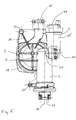
- Fig. 6 shows a rear view of the assembly similar Fig. 2
- the valve housing 4 on the side facing away from the connection piece 12, ie the upper end in the installed position, beyond the connection region to the pump housing 2, that is, the flow passage 24, extended to a Air trap 44 record.
- the extension 46 which receives the air separator 44, is also formed integrally with the valve housing 4 and the pump housing 2.
- the extension 46 at the upper end of the valve housing 4 is offset laterally relative to the longitudinal axis A of the valve housing, so that the longitudinal axis C of the extension 46 extends parallel to the longitudinal axis A of the valve housing 4. In this way, in the example shown, the air separator 44 can be arranged in the same plane next to the discharge nozzle 10.
Landscapes
- Engineering & Computer Science (AREA)
- Physics & Mathematics (AREA)
- Thermal Sciences (AREA)
- Chemical & Material Sciences (AREA)
- Combustion & Propulsion (AREA)
- Mechanical Engineering (AREA)
- General Engineering & Computer Science (AREA)
- Details Of Reciprocating Pumps (AREA)
- Basic Packing Technique (AREA)
- Yarns And Mechanical Finishing Of Yarns Or Ropes (AREA)
- Resistance Heating (AREA)
Claims (18)
- Unité modulaire pour une installation de chauffage compacte à deux circuits chauffants, un pour le chauffage de locaux et un pour le réchauffement d'eau sanitaire, comprenant une pompe de recirculation (6), disposée dans un carter de pompe (2), et un organe de commutation (36) disposé dans un carter de vanne (4), pour la commutation d'un flux de pompage, généré par la pompe de recirculation (6), entre les deux circuits chauffants,
caractérisée en ce que
au moins une partie du carter de pompe (2) est formée d'un seul tenant avec au moins une partie du carter de vanne (4), le carter de vanne (4) se rattachant alors à la face extérieure du carter de pompe (2) d'une manière telle, que le carter de vanne (4) coupe le carter de pompe (2), en ce sens que les corps de base géométriques du carter de vanne (4) et du carter de pompe (2) s'interpénètrent et que, dans la région d'intersection du carter de vanne (4) et du carter de pompe (2), l'intérieur du carter de vanne (4) et l'intérieur (16) du carter de pompe (2) soient placés en communication l'un avec l'autre et définissent un passage d'écoulement (24). - Unité modulaire selon la revendication 1, caractérisée en ce que le passage d'écoulement (24) relie l'intérieur (38) du carter de vanne (4) à l'aspiration de la pompe de recirculation (6).
- Unité modulaire selon la revendication 1 ou 2, caractérisée en ce que le carter de vanne (4) est réalisé sous une forme cylindrique et coupe alors le carter de pompe (2) dans sa région périphérique.
- Unité modulaire selon l'une des revendications précédentes, caractérisée en ce que le carter de pompe (2) est réalisé sous une forme cylindrique, une face d'extrémité étant alors fermée et le carter de vanne (4) coupant le carter de pompe (2) dans la région de cette face d'extrémité, de préférence située du côté arrière.
- Unité modulaire selon l'une des revendications précédentes, caractérisée en ce que les axes longitudinaux (A, B) du carter de pompe (2) et du carter de vanne (4) se développent dans des directions perpendiculaires l'une à l'autre et, de préférence, avec un écartement mutuel.
- Unité modulaire selon l'une des revendications précédentes, caractérisée en ce que le carter de vanne (4) présente deux embouts de raccordement (12, 14) pour être relié aux deux circuits chauffants, sachant qu'à partir de chacun des embouts de raccordement (12, 14), un tronçon de tube (28, 32) respectif s'étend dans l'espace intérieur (38) du carter de vanne (4), et que les extrémités libres des deux tronçons de tube (28, 32) sont placées à distance l'une de l'autre, se font mutuellement face et sont aménagées sous forme de sièges de soupape (30, 34).
- Unité modulaire selon la revendication 6, caractérisée en ce qu'entre une face extérieure des deux tronçons de tube (28, 32) et une paroi intérieure du carter de vanne (4) est formé un espace libre (38) qui, dans la région d'intersection entre le carter de pompe (2) et le carter de vanne (4), communique avec l'espace intérieur (16) du carter de pompe, pour former le passage d'écoulement (24).
- Unité modulaire selon la revendication 6 ou 7, caractérisée en ce que l'un au moins des deux tronçons de tube (28, 32), de préférence les deux tronçons de tube (28, 32), s'étendent dans la direction de l'axe longitudinal (A) du carter de vanne (4).
- Unité modulaire selon l'une des revendications 6 à 8, caractérisée en ce qu'un premier embout de raccordement (12) est réalisé sur une première face d'extrémité du carter de vanne (4) et s'étend, de préférence, dans la direction de l'axe longitudinal (A) du carter de vanne (4).
- Unité modulaire selon la revendication 8, caractérisée en ce que la première face d'extrémité (26) est conçue ouverte et l'embout de raccordement (12) est, avec le premier tronçon de tube (28) correspondant, réalisé sous forme d'une pièce rapportée, qui est insérée, sous étanchéité, dans la première face d'extrémité (26) ouverte.
- Unité modulaire selon l'une des revendications 6 à 10, caractérisée en ce qu'un deuxième embout de raccordement (14) est réalisé sur une surface périphérique du carter de vanne (4), de préférence à proximité d'une face d'extrémité située à l'opposé de la première face d'extrémité.
- Unité modulaire selon la revendication 11, caractérisée en ce que le deuxième embout de raccordement (14) s'étend dans une direction sensiblement perpendiculaire à l'axe longitudinal (A) du carter de vanne (4) et, de préférence, perpendiculaire à l'axe longitudinal (B) du carter de pompe (2).
- Unité modulaire selon la revendication 11 ou 12, caractérisée en ce que le deuxième embout de raccordement (14) ainsi que le deuxième tronçon de tube (30), se rattachant à celui-ci, sont formés d'un seul tenant avec le carter de vanne (4).
- Unité modulaire selon la revendication 13, caractérisée en ce que le deuxième embout de raccordement (14) et au moins une partie du deuxième tronçon de tube (30), se rattachant à celui-ci, ont été réalisés par le procédé de moulage par injection, à l'aide d'un noyau extractible par pivotement.
- Unité modulaire selon l'une des revendications précédentes, caractérisée en ce que le carter de pompe (2) présente un embout de refoulement (10), de préférence formé d'un seul tenant avec le carter de pompe (2), pour le raccordement d'un circuit chauffant, en particulier d'un circuit primaire de l'installation de chauffage.
- Unité modulaire selon la revendication 15, caractérisée en ce que l'embout de refoulement (10) a été réalisé par le procédé de moulage par injection, à l'aide d'un noyau extractible à vis.
- Unité modulaire selon l'une des revendications 6 à 16, caractérisée en ce que le premier embout de raccordement (12) du carter de vanne (4) s'étend vers un premier côté, en particulier le côté inférieur de l'unité modulaire, l'embout de refoulement (10) du carter de pompe (2) s'étend en sens inverse, vers un deuxième côté, tourné à l'opposé du premier coté, du module, et le deuxième embout de raccordement (14) du carter de vanne (4) s'étend dans une direction transversale à l'embout de refoulement (10) et au premier embout de raccordement (12).
- Unité modulaire selon l'une des revendications précédentes, caractérisée en ce que le carter de vanne (4) est, à son extrémité supérieure dans la position de montage, allongé au-delà du passage d'écoulement (24) menant au carter de pompe (2) et dans la région située au-dessus du passage d'écoulement (24) est disposé, dans le carter de vanne (4), un séparateur d'air.
Priority Applications (3)
| Application Number | Priority Date | Filing Date | Title |
|---|---|---|---|
| EP04006831A EP1580489B9 (fr) | 2004-03-22 | 2004-03-22 | Unité pour installation de chauffage compacte |
| AT04006831T ATE430290T1 (de) | 2004-03-22 | 2004-03-22 | Baueinheit für eine kompaktheizungsanlage |
| DE502004009414T DE502004009414D1 (de) | 2004-03-22 | 2004-03-22 | Baueinheit für eine Kompaktheizungsanlage |
Applications Claiming Priority (1)
| Application Number | Priority Date | Filing Date | Title |
|---|---|---|---|
| EP04006831A EP1580489B9 (fr) | 2004-03-22 | 2004-03-22 | Unité pour installation de chauffage compacte |
Publications (3)
| Publication Number | Publication Date |
|---|---|
| EP1580489A1 EP1580489A1 (fr) | 2005-09-28 |
| EP1580489B1 true EP1580489B1 (fr) | 2009-04-29 |
| EP1580489B9 EP1580489B9 (fr) | 2009-09-02 |
Family
ID=34854574
Family Applications (1)
| Application Number | Title | Priority Date | Filing Date |
|---|---|---|---|
| EP04006831A Expired - Lifetime EP1580489B9 (fr) | 2004-03-22 | 2004-03-22 | Unité pour installation de chauffage compacte |
Country Status (3)
| Country | Link |
|---|---|
| EP (1) | EP1580489B9 (fr) |
| AT (1) | ATE430290T1 (fr) |
| DE (1) | DE502004009414D1 (fr) |
Family Cites Families (5)
| Publication number | Priority date | Publication date | Assignee | Title |
|---|---|---|---|---|
| DE1119485B (de) * | 1959-06-06 | 1961-12-14 | Thermo Appbau G M B H | Wasserumwaelzpumpe, vorzugsweise fuer Sammelheizungsanlagen |
| CH364694A (fr) * | 1960-03-25 | 1962-09-30 | Emerjy Societe Anonyme | Pompe à vanne incorporée, pour installations de chauffage central |
| FR2258577A1 (en) * | 1974-01-22 | 1975-08-18 | Drouard Moteurs | Three-way pump for central heating system - has three outlets/inlets and motor coplanar for mounting in limited space |
| FR2646212B1 (fr) * | 1989-04-21 | 1994-04-15 | Icf | Appareil de circulation et de distribution de fluide |
| DE19717799C5 (de) | 1997-04-26 | 2007-02-08 | Grundfos A/S | Baueinheit für eine Kompaktheizungsanlage |
-
2004
- 2004-03-22 EP EP04006831A patent/EP1580489B9/fr not_active Expired - Lifetime
- 2004-03-22 DE DE502004009414T patent/DE502004009414D1/de not_active Expired - Lifetime
- 2004-03-22 AT AT04006831T patent/ATE430290T1/de not_active IP Right Cessation
Also Published As
| Publication number | Publication date |
|---|---|
| EP1580489B9 (fr) | 2009-09-02 |
| DE502004009414D1 (de) | 2009-06-10 |
| ATE430290T1 (de) | 2009-05-15 |
| EP1580489A1 (fr) | 2005-09-28 |
Similar Documents
| Publication | Publication Date | Title |
|---|---|---|
| EP4077989B1 (fr) | Vanne multivoies | |
| DE10195740B4 (de) | Ölfilter und Verfahren zu dessen Herstellung | |
| EP3156659B1 (fr) | Pompe et système hydraulique | |
| EP1519082A1 (fr) | Dispositif de commande et procédé pour embrayages commandés hydrauliquement | |
| EP3267042B1 (fr) | Groupe motopompe | |
| WO2018077348A1 (fr) | Dispositif de répartition d'eau de lave-vitre à soupapes multiples | |
| EP1130342B2 (fr) | Module pour installation de chauffage compacte | |
| EP1528330A1 (fr) | Ensemble pour installation de chauffage compact | |
| EP2230359A2 (fr) | Ensemble pour la liaison d'un puits d'inspection et d'une conduite d'évacuation | |
| EP0874201B1 (fr) | Ensemble pour installation de chauffage compact | |
| EP1418387B1 (fr) | Installation de chauffage compacte avec deux circuits de chauffage | |
| EP1884720B1 (fr) | Ensemble pour installation de chauffage compact | |
| EP1580489B9 (fr) | Unité pour installation de chauffage compacte | |
| EP4284670B1 (fr) | Réservoir de liquide pour un système de liquide d'un véhicule, système de liquide et véhicule | |
| DE20113499U1 (de) | Kunststoffkorrugationswellrohr mit monolithischem Behältnis | |
| EP4083481A1 (fr) | Soupape pour un système de liquide et système de liquide pour un véhicule | |
| EP3364043B1 (fr) | Groupe motopompe avec dispositif de purge d'air et de vidange intégré | |
| EP4400756B1 (fr) | Connecteur de ligne à faible résistance à l'écoulement | |
| WO2012152241A1 (fr) | Parcours hydraulique doté d'un dispositif d'évacuation de l'air | |
| EP1884723B1 (fr) | Module | |
| DE19942544C2 (de) | Hydraulische Lenkeinrichtung mit Übersetzungsänderung | |
| EP2481856B1 (fr) | Unité de soupape de remplissage | |
| EP0791772A2 (fr) | Soupape à trois voies pour jonction hydraulique | |
| EP4083482A1 (fr) | Soupape et réservoir de liquide pour un système de liquide, ainsi que système de liquide pour un véhicule | |
| EP1528371B1 (fr) | Ensemble pour installation de chauffage compact |
Legal Events
| Date | Code | Title | Description |
|---|---|---|---|
| PUAI | Public reference made under article 153(3) epc to a published international application that has entered the european phase |
Free format text: ORIGINAL CODE: 0009012 |
|
| AK | Designated contracting states |
Kind code of ref document: A1 Designated state(s): AT BE BG CH CY CZ DE DK EE ES FI FR GB GR HU IE IT LI LU MC NL PL PT RO SE SI SK TR |
|
| AX | Request for extension of the european patent |
Extension state: AL LT LV MK |
|
| 17P | Request for examination filed |
Effective date: 20050907 |
|
| AKX | Designation fees paid |
Designated state(s): AT BE BG CH CY CZ DE DK EE ES FI FR GB GR HU IE IT LI LU MC NL PL PT RO SE SI SK TR |
|
| 17Q | First examination report despatched |
Effective date: 20070316 |
|
| GRAP | Despatch of communication of intention to grant a patent |
Free format text: ORIGINAL CODE: EPIDOSNIGR1 |
|
| GRAS | Grant fee paid |
Free format text: ORIGINAL CODE: EPIDOSNIGR3 |
|
| GRAA | (expected) grant |
Free format text: ORIGINAL CODE: 0009210 |
|
| AK | Designated contracting states |
Kind code of ref document: B1 Designated state(s): AT BE BG CH CY CZ DE DK EE ES FI FR GB GR HU IE IT LI LU MC NL PL PT RO SE SI SK TR |
|
| REG | Reference to a national code |
Ref country code: GB Ref legal event code: FG4D Free format text: NOT ENGLISH |
|
| REG | Reference to a national code |
Ref country code: CH Ref legal event code: EP |
|
| REF | Corresponds to: |
Ref document number: 502004009414 Country of ref document: DE Date of ref document: 20090610 Kind code of ref document: P |
|
| REG | Reference to a national code |
Ref country code: IE Ref legal event code: FG4D |
|
| NLV1 | Nl: lapsed or annulled due to failure to fulfill the requirements of art. 29p and 29m of the patents act | ||
| PG25 | Lapsed in a contracting state [announced via postgrant information from national office to epo] |
Ref country code: FI Free format text: LAPSE BECAUSE OF FAILURE TO SUBMIT A TRANSLATION OF THE DESCRIPTION OR TO PAY THE FEE WITHIN THE PRESCRIBED TIME-LIMIT Effective date: 20090429 Ref country code: PT Free format text: LAPSE BECAUSE OF FAILURE TO SUBMIT A TRANSLATION OF THE DESCRIPTION OR TO PAY THE FEE WITHIN THE PRESCRIBED TIME-LIMIT Effective date: 20090829 Ref country code: ES Free format text: LAPSE BECAUSE OF FAILURE TO SUBMIT A TRANSLATION OF THE DESCRIPTION OR TO PAY THE FEE WITHIN THE PRESCRIBED TIME-LIMIT Effective date: 20090809 |
|
| PG25 | Lapsed in a contracting state [announced via postgrant information from national office to epo] |
Ref country code: PL Free format text: LAPSE BECAUSE OF FAILURE TO SUBMIT A TRANSLATION OF THE DESCRIPTION OR TO PAY THE FEE WITHIN THE PRESCRIBED TIME-LIMIT Effective date: 20090429 Ref country code: NL Free format text: LAPSE BECAUSE OF FAILURE TO SUBMIT A TRANSLATION OF THE DESCRIPTION OR TO PAY THE FEE WITHIN THE PRESCRIBED TIME-LIMIT Effective date: 20090429 Ref country code: SI Free format text: LAPSE BECAUSE OF FAILURE TO SUBMIT A TRANSLATION OF THE DESCRIPTION OR TO PAY THE FEE WITHIN THE PRESCRIBED TIME-LIMIT Effective date: 20090429 Ref country code: SE Free format text: LAPSE BECAUSE OF FAILURE TO SUBMIT A TRANSLATION OF THE DESCRIPTION OR TO PAY THE FEE WITHIN THE PRESCRIBED TIME-LIMIT Effective date: 20090729 |
|
| REG | Reference to a national code |
Ref country code: IE Ref legal event code: FD4D |
|
| PG25 | Lapsed in a contracting state [announced via postgrant information from national office to epo] |
Ref country code: RO Free format text: LAPSE BECAUSE OF FAILURE TO SUBMIT A TRANSLATION OF THE DESCRIPTION OR TO PAY THE FEE WITHIN THE PRESCRIBED TIME-LIMIT Effective date: 20090429 Ref country code: IE Free format text: LAPSE BECAUSE OF FAILURE TO SUBMIT A TRANSLATION OF THE DESCRIPTION OR TO PAY THE FEE WITHIN THE PRESCRIBED TIME-LIMIT Effective date: 20090429 Ref country code: CZ Free format text: LAPSE BECAUSE OF FAILURE TO SUBMIT A TRANSLATION OF THE DESCRIPTION OR TO PAY THE FEE WITHIN THE PRESCRIBED TIME-LIMIT Effective date: 20090429 Ref country code: EE Free format text: LAPSE BECAUSE OF FAILURE TO SUBMIT A TRANSLATION OF THE DESCRIPTION OR TO PAY THE FEE WITHIN THE PRESCRIBED TIME-LIMIT Effective date: 20090429 Ref country code: DK Free format text: LAPSE BECAUSE OF FAILURE TO SUBMIT A TRANSLATION OF THE DESCRIPTION OR TO PAY THE FEE WITHIN THE PRESCRIBED TIME-LIMIT Effective date: 20090429 |
|
| PG25 | Lapsed in a contracting state [announced via postgrant information from national office to epo] |
Ref country code: SK Free format text: LAPSE BECAUSE OF FAILURE TO SUBMIT A TRANSLATION OF THE DESCRIPTION OR TO PAY THE FEE WITHIN THE PRESCRIBED TIME-LIMIT Effective date: 20090429 |
|
| PLBE | No opposition filed within time limit |
Free format text: ORIGINAL CODE: 0009261 |
|
| STAA | Information on the status of an ep patent application or granted ep patent |
Free format text: STATUS: NO OPPOSITION FILED WITHIN TIME LIMIT |
|
| PG25 | Lapsed in a contracting state [announced via postgrant information from national office to epo] |
Ref country code: BG Free format text: LAPSE BECAUSE OF FAILURE TO SUBMIT A TRANSLATION OF THE DESCRIPTION OR TO PAY THE FEE WITHIN THE PRESCRIBED TIME-LIMIT Effective date: 20090729 |
|
| 26N | No opposition filed |
Effective date: 20100201 |
|
| BERE | Be: lapsed |
Owner name: GRUNDFOS A/S Effective date: 20100331 |
|
| PG25 | Lapsed in a contracting state [announced via postgrant information from national office to epo] |
Ref country code: GR Free format text: LAPSE BECAUSE OF FAILURE TO SUBMIT A TRANSLATION OF THE DESCRIPTION OR TO PAY THE FEE WITHIN THE PRESCRIBED TIME-LIMIT Effective date: 20090730 Ref country code: MC Free format text: LAPSE BECAUSE OF NON-PAYMENT OF DUE FEES Effective date: 20100331 |
|
| REG | Reference to a national code |
Ref country code: CH Ref legal event code: PL |
|
| PG25 | Lapsed in a contracting state [announced via postgrant information from national office to epo] |
Ref country code: LI Free format text: LAPSE BECAUSE OF NON-PAYMENT OF DUE FEES Effective date: 20100331 Ref country code: BE Free format text: LAPSE BECAUSE OF NON-PAYMENT OF DUE FEES Effective date: 20100331 Ref country code: CH Free format text: LAPSE BECAUSE OF NON-PAYMENT OF DUE FEES Effective date: 20100331 |
|
| PG25 | Lapsed in a contracting state [announced via postgrant information from national office to epo] |
Ref country code: AT Free format text: LAPSE BECAUSE OF NON-PAYMENT OF DUE FEES Effective date: 20100322 |
|
| PG25 | Lapsed in a contracting state [announced via postgrant information from national office to epo] |
Ref country code: CY Free format text: LAPSE BECAUSE OF FAILURE TO SUBMIT A TRANSLATION OF THE DESCRIPTION OR TO PAY THE FEE WITHIN THE PRESCRIBED TIME-LIMIT Effective date: 20090429 |
|
| PG25 | Lapsed in a contracting state [announced via postgrant information from national office to epo] |
Ref country code: HU Free format text: LAPSE BECAUSE OF FAILURE TO SUBMIT A TRANSLATION OF THE DESCRIPTION OR TO PAY THE FEE WITHIN THE PRESCRIBED TIME-LIMIT Effective date: 20091030 Ref country code: LU Free format text: LAPSE BECAUSE OF NON-PAYMENT OF DUE FEES Effective date: 20100322 |
|
| PG25 | Lapsed in a contracting state [announced via postgrant information from national office to epo] |
Ref country code: TR Free format text: LAPSE BECAUSE OF FAILURE TO SUBMIT A TRANSLATION OF THE DESCRIPTION OR TO PAY THE FEE WITHIN THE PRESCRIBED TIME-LIMIT Effective date: 20090429 |
|
| REG | Reference to a national code |
Ref country code: FR Ref legal event code: PLFP Year of fee payment: 13 |
|
| REG | Reference to a national code |
Ref country code: FR Ref legal event code: PLFP Year of fee payment: 14 |
|
| REG | Reference to a national code |
Ref country code: FR Ref legal event code: PLFP Year of fee payment: 15 |
|
| PGFP | Annual fee paid to national office [announced via postgrant information from national office to epo] |
Ref country code: GB Payment date: 20220324 Year of fee payment: 19 Ref country code: DE Payment date: 20220323 Year of fee payment: 19 |
|
| PGFP | Annual fee paid to national office [announced via postgrant information from national office to epo] |
Ref country code: FR Payment date: 20220323 Year of fee payment: 19 |
|
| PGFP | Annual fee paid to national office [announced via postgrant information from national office to epo] |
Ref country code: IT Payment date: 20220331 Year of fee payment: 19 |
|
| REG | Reference to a national code |
Ref country code: DE Ref legal event code: R082 Ref document number: 502004009414 Country of ref document: DE |
|
| REG | Reference to a national code |
Ref country code: DE Ref legal event code: R119 Ref document number: 502004009414 Country of ref document: DE |
|
| GBPC | Gb: european patent ceased through non-payment of renewal fee |
Effective date: 20230322 |
|
| PG25 | Lapsed in a contracting state [announced via postgrant information from national office to epo] |
Ref country code: GB Free format text: LAPSE BECAUSE OF NON-PAYMENT OF DUE FEES Effective date: 20230322 |
|
| PG25 | Lapsed in a contracting state [announced via postgrant information from national office to epo] |
Ref country code: GB Free format text: LAPSE BECAUSE OF NON-PAYMENT OF DUE FEES Effective date: 20230322 Ref country code: FR Free format text: LAPSE BECAUSE OF NON-PAYMENT OF DUE FEES Effective date: 20230331 Ref country code: DE Free format text: LAPSE BECAUSE OF NON-PAYMENT OF DUE FEES Effective date: 20231003 |
|
| PG25 | Lapsed in a contracting state [announced via postgrant information from national office to epo] |
Ref country code: IT Free format text: LAPSE BECAUSE OF NON-PAYMENT OF DUE FEES Effective date: 20230322 |