EP1580480A2 - Illumination device and or cover an illumination device - Google Patents
Illumination device and or cover an illumination device Download PDFInfo
- Publication number
- EP1580480A2 EP1580480A2 EP05005291A EP05005291A EP1580480A2 EP 1580480 A2 EP1580480 A2 EP 1580480A2 EP 05005291 A EP05005291 A EP 05005291A EP 05005291 A EP05005291 A EP 05005291A EP 1580480 A2 EP1580480 A2 EP 1580480A2
- Authority
- EP
- European Patent Office
- Prior art keywords
- cover
- reflector surface
- main part
- illumination element
- light
- Prior art date
- Legal status (The legal status is an assumption and is not a legal conclusion. Google has not performed a legal analysis and makes no representation as to the accuracy of the status listed.)
- Withdrawn
Links
- 238000005286 illumination Methods 0.000 title claims abstract description 51
- 230000003287 optical effect Effects 0.000 claims description 17
- 238000002347 injection Methods 0.000 claims description 3
- 239000007924 injection Substances 0.000 claims description 3
- 239000000463 material Substances 0.000 claims description 3
- 238000000034 method Methods 0.000 claims description 3
- 238000007740 vapor deposition Methods 0.000 claims description 3
- 238000005034 decoration Methods 0.000 claims description 2
- 230000005855 radiation Effects 0.000 claims description 2
- 238000004519 manufacturing process Methods 0.000 description 3
- 230000015572 biosynthetic process Effects 0.000 description 2
- 230000000295 complement effect Effects 0.000 description 2
- 238000009713 electroplating Methods 0.000 description 2
- 238000009434 installation Methods 0.000 description 2
- 238000012423 maintenance Methods 0.000 description 2
- 239000011248 coating agent Substances 0.000 description 1
- 238000000576 coating method Methods 0.000 description 1
- 238000004040 coloring Methods 0.000 description 1
- 238000010276 construction Methods 0.000 description 1
- 238000011161 development Methods 0.000 description 1
- 230000018109 developmental process Effects 0.000 description 1
- 230000000694 effects Effects 0.000 description 1
- 229910052754 neon Inorganic materials 0.000 description 1
- GKAOGPIIYCISHV-UHFFFAOYSA-N neon atom Chemical compound [Ne] GKAOGPIIYCISHV-UHFFFAOYSA-N 0.000 description 1
- 230000000007 visual effect Effects 0.000 description 1
Images
Classifications
-
- F—MECHANICAL ENGINEERING; LIGHTING; HEATING; WEAPONS; BLASTING
- F21—LIGHTING
- F21V—FUNCTIONAL FEATURES OR DETAILS OF LIGHTING DEVICES OR SYSTEMS THEREOF; STRUCTURAL COMBINATIONS OF LIGHTING DEVICES WITH OTHER ARTICLES, NOT OTHERWISE PROVIDED FOR
- F21V3/00—Globes; Bowls; Cover glasses
- F21V3/04—Globes; Bowls; Cover glasses characterised by materials, surface treatments or coatings
-
- F—MECHANICAL ENGINEERING; LIGHTING; HEATING; WEAPONS; BLASTING
- F21—LIGHTING
- F21V—FUNCTIONAL FEATURES OR DETAILS OF LIGHTING DEVICES OR SYSTEMS THEREOF; STRUCTURAL COMBINATIONS OF LIGHTING DEVICES WITH OTHER ARTICLES, NOT OTHERWISE PROVIDED FOR
- F21V5/00—Refractors for light sources
- F21V5/02—Refractors for light sources of prismatic shape
-
- F—MECHANICAL ENGINEERING; LIGHTING; HEATING; WEAPONS; BLASTING
- F21—LIGHTING
- F21V—FUNCTIONAL FEATURES OR DETAILS OF LIGHTING DEVICES OR SYSTEMS THEREOF; STRUCTURAL COMBINATIONS OF LIGHTING DEVICES WITH OTHER ARTICLES, NOT OTHERWISE PROVIDED FOR
- F21V7/00—Reflectors for light sources
- F21V7/04—Optical design
- F21V7/09—Optical design with a combination of different curvatures
-
- F—MECHANICAL ENGINEERING; LIGHTING; HEATING; WEAPONS; BLASTING
- F21—LIGHTING
- F21V—FUNCTIONAL FEATURES OR DETAILS OF LIGHTING DEVICES OR SYSTEMS THEREOF; STRUCTURAL COMBINATIONS OF LIGHTING DEVICES WITH OTHER ARTICLES, NOT OTHERWISE PROVIDED FOR
- F21V7/00—Reflectors for light sources
- F21V7/22—Reflectors for light sources characterised by materials, surface treatments or coatings, e.g. dichroic reflectors
- F21V7/28—Reflectors for light sources characterised by materials, surface treatments or coatings, e.g. dichroic reflectors characterised by coatings
-
- F—MECHANICAL ENGINEERING; LIGHTING; HEATING; WEAPONS; BLASTING
- F21—LIGHTING
- F21V—FUNCTIONAL FEATURES OR DETAILS OF LIGHTING DEVICES OR SYSTEMS THEREOF; STRUCTURAL COMBINATIONS OF LIGHTING DEVICES WITH OTHER ARTICLES, NOT OTHERWISE PROVIDED FOR
- F21V17/00—Fastening of component parts of lighting devices, e.g. shades, globes, refractors, reflectors, filters, screens, grids or protective cages
- F21V17/10—Fastening of component parts of lighting devices, e.g. shades, globes, refractors, reflectors, filters, screens, grids or protective cages characterised by specific fastening means or way of fastening
- F21V17/12—Fastening of component parts of lighting devices, e.g. shades, globes, refractors, reflectors, filters, screens, grids or protective cages characterised by specific fastening means or way of fastening by screwing
Definitions
- the invention relates to an illumination element for the electrical illumination of installations, Buildings or passenger cabins of rides, e.g. Ferris wheel or Bumper cars at folk festivals.
- the prior art already uses electrical lighting means, e.g. lights known mainly as a visual eye-catcher, neon sign or as illuminated Decoration of rides serve at folk festivals.
- electrical lighting means e.g. lights known mainly as a visual eye-catcher, neon sign or as illuminated Decoration of rides serve at folk festivals.
- the well-known Illumination elements have the disadvantage that they consist of a large number of components are composed, which both the cost of production and the cost of their assembly and maintenance increases.
- An object of the present invention is therefore an illumination element to provide, which consists of a small number of components. Another The object of the present invention is to provide an illumination element, the light radiates in a visually appealing way.
- the illumination element according to the invention comprises a main part, the one Reflector surface for reflection and radiation generated by a light source Having light rays, wherein at the main part at least one of the lighting means receiving portion is integrally formed. Due to the integral, i. integral formation of the main body along with the section that is to take up the illuminant is used, the number of components in the inventive Illuminating element compared to known Illuminationselement reduced what both reduced manufacturing costs and the cost of installation and maintenance. It it is also possible, several serving to receive bulbs sections integrally in one piece with the main part of the Illuminationselements to For example, to increase the luminous intensity of the illumination element. The order the lighting means in the serving to receive the light emitting portion of the Illuminating element is preferably carried out so that a maximum proportion of the Illuminant generated light rays falls on the reflector surface.
- a bulb holding the socket via a connector or a Screw thread is received in the relevant section on the main body.
- the Reflector surface provided an opening for the light source, so that the Illuminant is surrounded by the reflector surface.
- the reflector surface preferably spherically formed to the generated by the bulb To bundle light rays and thus to achieve a higher luminance.
- the Reflector surface on a structuring the scattering and / or interference of the caused by the light bulb generated light rays. It has turned out to be special Advantageously, when the reflector surface a number of substantially Having tetrahedral structuring elements, preferably evenly over the reflector surface are arranged distributed. These can be the tetrahedral Structuring elements be pyramid-shaped and / or an elongated shape in the manner of a gable roof.
- the height with which the over the Reflector surface distributed tetrahedral structuring elements of the Protruding reflector surface is preferably about 0.5 mm to 2 mm, while the edge length at the base of the tetrahedral structuring elements in one Range of about 0.5 mm to 5 mm.
- the structuring of the reflector surface with such tetrahedral structuring elements causes a special scattering or interference of the light beams generated by the light source, which is a exceptionally appealing optical effect of the illumination element with it brings.
- the handling of the illumination element according to the invention is during assembly facilitated by the reflector surface or the main part of the Illuminationselements at least one opening for the implementation of fasteners for attachment of the illumination element.
- This allows the illumination element with its the Reflector surface opposite bottom created on a mounting surface while the fasteners are easily accessible from one side through the Openings are guided and fixed in the reflector surface. Due to the integral formation of the main part of the illumination element together with the Section that serves to accommodate the bulb is after attaching the Main part of the illumination element no further measure to attach the Illumination element required.
- the reflector surface with a shiny metallic layer coated to optimize the reflection properties of the reflector surface and thus to increase the luminosity of the illumination element.
- Coating the Reflector surface with a shiny metallic layer is preferably carried out by means of a vapor deposition or electroplating process.
- Another aspect of the present invention relates to a cover for a Illumination element, which is the reflector surface of the illumination element at least partially covering and by coloring and construction to the optical Appearance of the illumination element contributes significantly.
- the above Tasks are further by a cover according to the invention for a Illuminating element, in particular for an illumination element of the above-described Kind solved by the cover at least one transparent part for the passage of the light rays generated by the light source, in which at least one element for optical scattering generated by the illuminant of the Illuminationselements Light rays is provided, wherein in the transparent part of the cover a number of substantially straight, in pairs at an angle to each other arranged surfaces are provided.
- the arrangement of essentially straight, in pairs at an angle to each other arranged surfaces in transparent part of the cover causes a surprisingly attractive optical Effect by prismatic refraction and scattering of the light produced by the bulb Light beams.
- the cover according to the invention for a Illumination element are those in the transparent part of the cover in pairs arranged surfaces disposed immediately adjacent to each other so that they are in lie at a shallow angle to each other.
- the pairs form arranged surfaces in the transparent part of the cover, an optical prism, which intensifies the above-mentioned optical effect.
- the paired surfaces distributed stem-shaped over the cover are arranged, wherein the surfaces in each case towards the center of the cover rejuvenate. This arrangement gives one with the cover according to the invention equipped illumination element even then a visually pleasing appearance, if the bulb does not light up.
- the cover has a substantially circular floor plan and is over a Plug connection or a screw thread with the Illuminationselement coupled to to at least partially cover a reflector surface of the illumination element.
- a Plug connection or a screw thread with the Illuminationselement coupled to to at least partially cover a reflector surface of the illumination element.
- the one for the passage of the light rays provided part of the cover is at least partially made of a transparent Made material, which is preferably colored to the light generated by the bulb to give a corresponding color.
- At least portions of a thread are provided on the cover as well as on Main part of the Illuminationselements at least portions of the thread to the Cover provided complementarily shaped thread, respectively cooperate to the cover on the main part of the illumination element to Fasten.
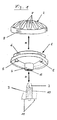
- Figure 1 shows a perspective view of an illumination element according to a first embodiment of the present invention with a main part 1, a Cover 2 and a lamp 3. These three components 1, 2, and 3 of Illuminating element according to the invention are separated from each other in FIG are shown and for the assembly of the Illuminationselements in by the Double Arrows A Assembled direction.
- a the Illuminant 3 receiving portion 4 integral, i. formed in an injection molded part. Due to the one-piece design of the main part 1 together with the for recording of the illuminant 3 suitable section 4, the number of components in the reduced illumination element according to the invention.
- a spherical reflector surface 13 is formed, which will be described in more detail below in connection with FIG.
- the Reflector surface 13 is due to the perspective view in Figure 1 only from to see the bottom.
- the main part 1 points at his Side threaded sections 6, which serve to fasten the cover 2.
- a screw thread 12th formed, which serves to fasten the lamp 3.
- the bulb 3 is held by a socket 10, at the bottom of electrical Connections 11 are arranged for the lamp 3.
- a screw thread 9 designed for attachment to the main part 1, that to the formed on the inside of the section 4 screw thread 12th is complementary.
- the arrangement of the lamp 3 in the for receiving the Illuminant 3 serving section 4 of the main part 1 is made by inserting and Screwing the socket 10 in the section 4, wherein the screw thread 9 on the outer side surface of the socket 10 and the screw thread 12 on the inside of the Interlock section 4.
- the version 10 of the bulb 3 is so far in screwed the section 4 until the bulb 3 from the reflector surface thirteenth protrudes and a maximum proportion of the light rays generated by the light source 3 the reflector surface 13 falls.
- the cover 2 of the Illuminationselements has like the main part 1 a circular Floor plan and is in the embodiment shown in the drawings in the Art a convex hood shaped.
- the cover 2 is made of a transparent colored Material prepared so that the light rays generated by the light source 3 through the Cover 2 can escape from the Illuminationselement.
- At the edge of the cover 2 are formed on the inside of sections 8 of a screw thread, the Attachment of the cover 2 on the main part 1 is used.
- At the main part 1 are on one side outer surface portions 6 of a screw thread formed to the on the inside of the cover 2 formed screw thread 8 is complementary.
- the Arrangement of the cover 2 on the main body 1 is done by placing and untwisting the cover 10, the main part 1, wherein the screw thread 8 on the inside of the Cover 2 and formed on the main part 1 screw thread 6 into each other to grab.
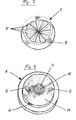
- FIG. 2 shows a perspective view of a cover for an illumination element according to the illustrated in Figure 1 embodiment of the present invention, wherein a perspective is shown in the hood-like cover 2.
- a perspective is shown in the hood-like cover 2.
- the middle part of the Cover 1 for the passage of the light rays generated by the light source 3 is provided has a number of not shown in the drawing
- the elements for optical scattering consist in each case of two substantially straight, in pairs at an angle to each other arranged surfaces 7. Thereby The elements for optical scattering produce an optical effect through prismatic Refraction and scattering of the light beams generated by the light source 3.
- those in the convex hood of the cover 2 are in pairs arranged surfaces 7 disposed immediately adjacent to each other so that they lie at a shallow angle to each other.
- the pairs form arranged surfaces 7 each have an optical prism, which is the above causes optical effect.
- the pairs of surfaces are 7 arranged in a star shape distributed over the cover 2, leaving a kind of rosette results, wherein the surfaces 7 each geometrically to the center of the cover 2 out be narrowed conditionally.
- This arrangement of pairs and star-shaped over the Cover 2 distributed elements for optical scattering causes a Kaleidoskopartigen effect and gives the illumination element according to the invention a visually attractive appearance.
- FIG. 3 shows a perspective view of the main part 1 of an illumination element without lamp and cover according to that shown in Figures 1 and 2 Embodiment of the present invention, wherein a perspective on the top of the main part 1 is shown.
- the spherical Reflector surface 13 is formed, in the center of which there is an opening in the Interior of section 4 leads, which serves to receive the bulb 3.
- main part 1 of the illumination element is located in the section 4 no light source 3, so that the formed on the inside of the section 4 Screw thread 12 is visible.
- the reflector surface 13 has two more Openings 5, which serve to carry out fastening means.
- the threaded portions 6 formed for the attachment of the cover 2.
- the reflector surface 13 has a structuring which is not shown in the drawings is shown in more detail.
- the structuring causes scattering and / or interference the light beams generated by the lamp 3.
- the reflector surface 13 a number of substantially projecting tetrahedral structuring elements which are substantially are distributed uniformly over the reflector surface 13.
- the tetrahedral structuring elements are in the middle region of Reflector surface 13 formed pyramid-shaped and have in the outer region of the Reflector surface 13 an elongated shape in the manner of a gable roof.
- the height at which the distributed over the reflector surface 13 tetrahedral Structuring elements protrude from the reflector surface 13, is about 0.5 mm to 2 mm, while the edge length at the base of the tetrahedral Structuring elements are in a range of about 0.5 mm to 5 mm.
- the Structuring of the reflector surface 13 with tetrahedral structuring elements in the manner described above causes a special scattering or interference of the light generated by the bulb, which is an exceptionally attractive optical effect of the illumination element result.
- the reflector surface 13 is provided with a metallic shiny layer by a Vapor deposition or electroplating process coated to reflect the reflective properties to improve the reflector surface and the luminosity of the illumination element to increase.
- the main body 1, the cover 2 of the illumination element and the socket 10 of the luminous means 3 are each manufactured as injection-molded parts made of plastic.
Landscapes
- Engineering & Computer Science (AREA)
- General Engineering & Computer Science (AREA)
- Non-Portable Lighting Devices Or Systems Thereof (AREA)
- Illuminated Signs And Luminous Advertising (AREA)
- Instrument Panels (AREA)
Abstract
Description
Die Erfindung betrifft ein Illuminationselement zur elektrischen Beleuchtung von Anlagen, Aufbauten oder Personenkabinen von Fahrgeschäften, wie z.B. Riesenrad- oder Autoscooter-Anlagen auf Volksfesten.The invention relates to an illumination element for the electrical illumination of installations, Buildings or passenger cabins of rides, e.g. Ferris wheel or Bumper cars at folk festivals.
Im Stand der Technik sind bereits elektrische Beleuchtungsmittel, wie z.B. Lichterketten bekannt, die hauptsächlich als optischer Blickfang, Lichtreklame oder als illuminierte Dekoration von Fahrgeschäften auf Volksfesten dienen. Die bekannten Illuminationselemente haben den Nachteil, dass sie aus einer Vielzahl von Bauteilen zusammengesetzt sind, was sowohl die Herstellungskosten als auch den Aufwand für deren Montage und Wartung erhöht.The prior art already uses electrical lighting means, e.g. lights known mainly as a visual eye-catcher, neon sign or as illuminated Decoration of rides serve at folk festivals. The well-known Illumination elements have the disadvantage that they consist of a large number of components are composed, which both the cost of production and the cost of their assembly and maintenance increases.
Eine Aufgabe der vorliegenden Erfindung ist es daher, ein Illuminationselement bereitzustellen, das aus einer geringen Anzahl von Bauteilen besteht. Eine weitere Aufgabe der vorliegenden Erfindung besteht darin, ein Illuminationselement zu schaffen, das Licht auf optisch ansprechende Weise abstrahlt.An object of the present invention is therefore an illumination element to provide, which consists of a small number of components. Another The object of the present invention is to provide an illumination element, the light radiates in a visually appealing way.
Diese Aufgaben werden durch das erfindungsgemäße Illuminationselement mit den
Merkmalen gemäß Anspruch 1 sowie durch eine erfindungsgemäße Abdeckung für ein
Illuminationselement mit den in Anspruch 9 spezifizierten Merkmalen gelöst. Vorteilhafte
Weiterbildungen der vorliegenden Erfindung sind in den Unteransprüchen 2 bis 8 und 10
bis 15 gekennzeichnet. These objects are achieved by the illumination element according to the invention with the
Features according to claim 1 and by a cover according to the invention for a
Illuminating element solved with the features specified in
Das erfindungsgemäße Illuminationselement umfasst einen Hauptteil, der eine Reflektoroberfläche zur Reflexion und Abstrahlung der von einem Leuchtmittel erzeugten Lichtstrahlen aufweist, wobei an dem Hauptteil mindestens ein das Leuchtmittel aufnehmender Abschnitt integral ausgebildet ist. Aufgrund der integralen, d.h. einstückigen Ausbildung des Hauptteils zusammen mit dem Abschnitt, der zur Aufnahme des Leuchtmittels dient, wird die Anzahl der Bauteile bei dem erfindungsgemäßen Illuminationselement gegenüber bekannten Illuminationselement reduziert, was sowohl die Herstellungskosten als auch den Aufwand für die Montage und Wartung verringert. Es ist auch möglich, mehrere zur Aufnahme von Leuchtmitteln dienende Abschnitte integral in einem Stück mit dem Hauptteil des Illuminationselements auszubilden, um beispielsweise die Leuchtintensität des Illuminationselement zu erhöhen. Die Anordnung des Leuchtmittels in dem zur Aufnahme des Leuchtmittels dienenden Abschnitt des Illuminationselements erfolgt dabei vorzugsweise so, dass ein maximaler Anteil der vom Leuchtmittel erzeugten Lichtstrahlen auf die Reflektoroberfläche fällt.The illumination element according to the invention comprises a main part, the one Reflector surface for reflection and radiation generated by a light source Having light rays, wherein at the main part at least one of the lighting means receiving portion is integrally formed. Due to the integral, i. integral formation of the main body along with the section that is to take up the illuminant is used, the number of components in the inventive Illuminating element compared to known Illuminationselement reduced what both reduced manufacturing costs and the cost of installation and maintenance. It it is also possible, several serving to receive bulbs sections integrally in one piece with the main part of the Illuminationselements to For example, to increase the luminous intensity of the illumination element. The order the lighting means in the serving to receive the light emitting portion of the Illuminating element is preferably carried out so that a maximum proportion of the Illuminant generated light rays falls on the reflector surface.
Bei einer bevorzugten Ausführungsform der vorliegenden Erfindung ist der mit dem Hauptteil integral ausgebildete Abschnitt zur Aufnahme des Leuchtmittels so geformt, dass mindestens ein vorzugsweise elektrisches Leuchtmittel darin untergebracht werden kann, indem eine das Leuchtmittel haltende Fassung über eine Steckverbindung oder ein Schraubgewinde in dem betreffenden Abschnitt am Hauptteil aufgenommen wird. Dadurch kann ein Austausch des Leuchtmittels aus dem Illuminationselement auf schnelle und einfache Weise vorgenommen werden. Zweckmäßigerweise ist in der Reflektoroberfläche eine Öffnung für das Leuchtmittel vorgesehen, so dass das Leuchtmittel von der Reflektoroberfläche umgeben ist. Dabei ist die Reflektoroberfläche vorzugsweise sphärisch ausgebildet, um die von dem Leuchtmittel erzeugten Lichtstrahlen zu bündeln und damit eine höhere Leuchtdichte zu erzielen.In a preferred embodiment of the present invention is with the Main part integrally formed section for receiving the bulb shaped so that at least one preferably electric lighting means are housed therein can, by a bulb holding the socket via a connector or a Screw thread is received in the relevant section on the main body. As a result, an exchange of the illuminant from the Illuminationselement on fast and easy way to be made. Conveniently, in the Reflector surface provided an opening for the light source, so that the Illuminant is surrounded by the reflector surface. Here is the reflector surface preferably spherically formed to the generated by the bulb To bundle light rays and thus to achieve a higher luminance.
Bei einer weiteren bevorzugten Ausführungsform der vorliegenden Erfindung weist die Reflektoroberfläche eine Strukturierung auf, die eine Streuung und/oder Interferenzen der von dem Leuchtmittel erzeugten Lichtstrahlen verursacht. Dabei hat es sich als besonders vorteilhaft herausgestellt, wenn die Reflektoroberfläche eine Anzahl von im wesentlichen tetraederförmigen Strukturierungselementen aufweist, die vorzugsweise gleichmäßig über die Reflektoroberfläche verteilt angeordnet sind. Dazu können die tetraederförmigen Strukturierungselemente pyramidenförmig ausgebildet sein und/oder eine längliche Form in der Art eines Giebeldachs aufweisen. Die Höhe, mit der die über die Reflektoroberfläche verteilten tetraederförmigen Strukturierungselemente von der Reflektoroberfläche hervorstehen, beträgt vorzugsweise ca. 0,5 mm bis 2 mm, während die Kantenlänge an der Basis der tetraederförmigen Strukturierungselemente in einem Bereich von ca. 0,5 mm bis 5 mm liegen. Die Strukturierung der Reflektoroberfläche mit solchen tetraederförmigen Strukturierungselementen bewirkt eine besondere Streuung bzw. Interferenz der durch das Leuchtmittel erzeugten Lichtstrahlen, was eine außergewöhnlich ansprechende optische Wirkung des Illuminationselements mit sich bringt.In a further preferred embodiment of the present invention, the Reflector surface on a structuring, the scattering and / or interference of the caused by the light bulb generated light rays. It has turned out to be special Advantageously, when the reflector surface a number of substantially Having tetrahedral structuring elements, preferably evenly over the reflector surface are arranged distributed. These can be the tetrahedral Structuring elements be pyramid-shaped and / or an elongated shape in the manner of a gable roof. The height with which the over the Reflector surface distributed tetrahedral structuring elements of the Protruding reflector surface, is preferably about 0.5 mm to 2 mm, while the edge length at the base of the tetrahedral structuring elements in one Range of about 0.5 mm to 5 mm. The structuring of the reflector surface with such tetrahedral structuring elements causes a special scattering or interference of the light beams generated by the light source, which is a exceptionally appealing optical effect of the illumination element with it brings.
Die Handhabung des erfindungsgemäßen Illuminationselements wird bei der Montage erleichtert, indem die Reflektoroberfläche bzw. der Hauptteil des Illuminationselements mindestens eine Öffnung zur Durchführung von Befestigungsmitteln für die Befestigung des Illuminationselements aufweist. Dadurch kann das Illuminationselement mit seiner der Reflektoroberfläche gegenüberliegenden Unterseite auf einer Montagefläche angelegt werden, während die Befestigungsmittel auf einfache Weise von einer Seite durch die Öffnungen in der Reflektoroberfläche geführt und befestigt werden. Aufgrund der integralen Ausbildung des Hauptteils des Illuminationselements zusammen mit dem Abschnitt, der zur Aufnahme des Leuchtmittels dient, ist nach der Befestigung des Hauptteils des Illuminationselements keine weitere Maßnahme zur Befestigung des Illuminationselement erforderlich.The handling of the illumination element according to the invention is during assembly facilitated by the reflector surface or the main part of the Illuminationselements at least one opening for the implementation of fasteners for attachment of the illumination element. This allows the illumination element with its the Reflector surface opposite bottom created on a mounting surface while the fasteners are easily accessible from one side through the Openings are guided and fixed in the reflector surface. Due to the integral formation of the main part of the illumination element together with the Section that serves to accommodate the bulb is after attaching the Main part of the illumination element no further measure to attach the Illumination element required.
Zweckmäßigerweise ist die Reflektoroberfläche mit einer metallisch glänzenden Schicht überzogen, um die Reflexionseigenschaften der Reflektoroberfläche zu optimieren und damit die Leuchtstärke des Illuminationselements zu erhöhen. Das Beschichten der Reflektoroberfläche mit einer metallisch glänzenden Schicht erfolgt dabei vorzugsweise mittels eines Bedampfen- oder Galvanisierungsverfahren.Conveniently, the reflector surface with a shiny metallic layer coated to optimize the reflection properties of the reflector surface and thus to increase the luminosity of the illumination element. Coating the Reflector surface with a shiny metallic layer is preferably carried out by means of a vapor deposition or electroplating process.
Ein weiterer Aspekt der vorliegenden Erfindung bezieht sich auf eine Abdeckung für ein Illuminationselement, welche die Reflektoroberfläche des Illuminationselements zumindest teilweise abdeckt und durch Farbgebung sowie Aufbau zu dem optischen Erscheinungsbild des Illuminationselements wesentlich beiträgt. Die oben genannten Aufgaben werden ferner wird durch eine erfindungsgemäße Abdeckung für ein Illuminationselement, insbesondere für ein Illuminationselement der oben beschriebenen Art gelöst, indem die Abdeckung zumindest einen transparenten Teil für den Durchtritt der vom Leuchtmittel erzeugten Lichtstrahlen aufweist, in dem mindestens ein Element zur optischen Streuung der von dem Leuchtmittel des Illuminationselements erzeugten Lichtstrahlen vorgesehen ist, wobei in dem transparenten Teil der Abdeckung eine Anzahl von im wesentlichen geraden, jeweils paarweise in einem Winkel zueinander angeordneten Oberflächen vorgesehen sind. Die Anordnung von im wesentlichen geraden, jeweils paarweise in einem Winkel zueinander angeordneten Oberflächen im transparenten Teil der Abdeckung bewirkt eine überraschend ansprechende optischen Effekt durch prismatische Brechung und Streuung der von dem Leuchtmittel erzeugten Lichtstrahlen.Another aspect of the present invention relates to a cover for a Illumination element, which is the reflector surface of the illumination element at least partially covering and by coloring and construction to the optical Appearance of the illumination element contributes significantly. The above Tasks are further by a cover according to the invention for a Illuminating element, in particular for an illumination element of the above-described Kind solved by the cover at least one transparent part for the passage of the light rays generated by the light source, in which at least one element for optical scattering generated by the illuminant of the Illuminationselements Light rays is provided, wherein in the transparent part of the cover a number of substantially straight, in pairs at an angle to each other arranged surfaces are provided. The arrangement of essentially straight, in pairs at an angle to each other arranged surfaces in transparent part of the cover causes a surprisingly attractive optical Effect by prismatic refraction and scattering of the light produced by the bulb Light beams.
Bei einer bevorzugten Ausführungsform der erfindungsgemäßen Abdeckung für ein Illuminationselement sind die im transparenten Teil der Abdeckung paarweise angeordneten Oberflächen unmittelbar aneinander angrenzend angeordnet, so dass sie in einem flachen Winkel zueinander liegen. Auf diese Weise bilden die paarweise angeordneten Oberflächen im transparenten Teil der Abdeckung ein optisches Prisma, was den oben genannten optischen Effekt intensiviert. Besonders vorteilhaft ist es, wenn die paarweise angeordneten Oberflächen stemförmig über die Abdeckung verteilt angeordnet sind, wobei sich die Oberflächen jeweils zur Mitte der Abdeckung hin verjüngen. Diese Anordnung verleiht einem mit der erfindungsgemäßen Abdeckung ausgestatteten Illuminationselement auch dann ein optisch ansprechendes Aussehen, wenn das Leuchtmittel nicht leuchtet.In a preferred embodiment of the cover according to the invention for a Illumination element are those in the transparent part of the cover in pairs arranged surfaces disposed immediately adjacent to each other so that they are in lie at a shallow angle to each other. In this way, the pairs form arranged surfaces in the transparent part of the cover, an optical prism, which intensifies the above-mentioned optical effect. It is particularly advantageous if the paired surfaces distributed stem-shaped over the cover are arranged, wherein the surfaces in each case towards the center of the cover rejuvenate. This arrangement gives one with the cover according to the invention equipped illumination element even then a visually pleasing appearance, if the bulb does not light up.
Bei einer weiteren bevorzugten Ausführungsform der erfindungsgemäßen Abdeckung weist die Abdeckung einen im wesentlichen kreisrunden Grundriss auf und ist über eine Steckverbindung oder ein Schraubgewinde mit dem Illuminationselement koppelbar, um eine Reflektoroberfläche des Illuminationselements zumindest teilweise abzudecken. Auf diese Weise liegt der für den Durchtritt der vom Leuchtmittel erzeugten Lichtstrahlen vorgesehene Teil der Abdeckung unmittelbar über der Reflektoroberfläche, die das vom Leuchtmittel erzeugte Licht bündelt und reflektiert. Der für den Durchtritt der Lichtstrahlen vorgesehene Teil der Abdeckung ist zumindest teilweise aus einem transparenten Material gefertigt, das vorzugsweise gefärbt ist, um dem vom Leuchtmittel erzeugten Licht eine entsprechende Farbe zu verleihen. In a further preferred embodiment of the cover according to the invention The cover has a substantially circular floor plan and is over a Plug connection or a screw thread with the Illuminationselement coupled to to at least partially cover a reflector surface of the illumination element. On This is the case for the passage of the light beams generated by the light source provided part of the cover immediately above the reflector surface, the from the Bulb generated light bundles and reflects. The one for the passage of the light rays provided part of the cover is at least partially made of a transparent Made material, which is preferably colored to the light generated by the bulb to give a corresponding color.
Um die Abdeckung mit dem Illuminationselement über ein Schraubgewinde zu verbinden, sind bei einer weiteren bevorzugten Ausführungsform der vorliegenden Erfindung sowohl an der Abdeckung zumindest Abschnitte eines Gewindes vorgesehen sind als auch am Hauptteil des Illuminationselements zumindest Abschnitte eines zu dem Gewinde an der Abdeckung komplementär ausgebildeten Gewindes vorgesehen, die jeweils zusammenwirken, um die Abdeckung am Hauptteil des Illuminationselements zu befestigen. Eine kostengünstige Herstellung lässt sich erzielen, wenn der Hauptteil und/oder die Abdeckung des Illuminationselements aus Kunststoff vorzugsweise als Spritzgussteile gefertigt sind.To connect the cover to the illumination element via a screw thread, are both in a further preferred embodiment of the present invention at least portions of a thread are provided on the cover as well as on Main part of the Illuminationselements at least portions of the thread to the Cover provided complementarily shaped thread, respectively cooperate to the cover on the main part of the illumination element to Fasten. An inexpensive production can be achieved if the main part and / or the cover of the illumination element made of plastic preferably as Injection molded parts are made.
Im Folgenden wird die vorliegende Erfindung anhand eines bevorzugten Ausführungsbeispiels unter Bezugnahme auf die beigefügten Zeichnungen näher erläutert. Es zeigen:
- Figur 1
- eine perspektivische Darstellung eines Illuminationselements gemäß einer ersten Ausführungsform der vorliegenden Erfindung;
Figur 2- eine perspektivische Ansicht einer Abdeckung für ein Illuminationselement gemäß der in Figur 1 dargestellten Ausführungsform der vorliegenden Erfindung; und
Figur 3- eine perspektivische Aufsicht auf den Hauptteil eines Illuminationselements ohne Leuchtmittel und Abdeckung gemäß der in den Figuren 1 und 2 dargestellten Ausführungsform der vorliegenden Erfindung.
- FIG. 1
- a perspective view of an illumination element according to a first embodiment of the present invention;
- FIG. 2
- a perspective view of a cover for an illumination element according to the embodiment of the present invention shown in Figure 1; and
- FIG. 3
- a perspective top view of the main part of a Illuminationselements without bulbs and cover according to the embodiment of the present invention shown in Figures 1 and 2.
Figur 1 zeigt eine perspektivische Darstellung eines Illuminationselements gemäß einer
ersten Ausführungsform der vorliegenden Erfindung mit einem Hauptteil 1, einer
Abdeckung 2 und einem Leuchtmittel 3. Diese drei Bauteile 1, 2, und 3 des
erfindungsgemäßen Illuminationselements sind in der Figur 1 voneinander getrennt
dargestellt und werden für den Zusammenbau des Illuminationselements in der durch die
Doppelpfeile A angedeuteten Richtung zusammengesetzt. An dem Hauptteil ist ein das
Leuchtmittel 3 aufnehmender Abschnitt 4 integral, d.h. in einem Spritzgussteil ausgebildet.
Aufgrund der einstückigen Ausbildung des Hauptteils 1 zusammen mit dem zur Aufnahme
des Leuchtmittels 3 geeigneten Abschnitt 4, wird die Anzahl der Bauteile bei dem
erfindungsgemäßen Illuminationselement reduziert.Figure 1 shows a perspective view of an illumination element according to a
first embodiment of the present invention with a main part 1, a
Auf der Oberseite des Hauptteils 1 ist eine sphärische Reflektoroberfläche 13 ausgebildet,
die nachfolgend im Zusammenhang mit Figur 3 näher beschrieben wird. Die
Reflektoroberfläche 13 ist aufgrund der perspektivischen Darstellung in Figur 1 nur von
der Unterseite zu sehen. In der Reflektoroberfläche 13 befinden sich Bohrungen 5 für die
Durchführung von Befestigungsmitteln (nicht dargestellt). Der Hauptteil 1 weist an seiner
Seite Gewindeabschnitte 6 auf, die zur Befestigung der Abdeckung 2 dienen. Auf der
Innenseite des Abschnitts 4 zur Aufnahme des Leuchtmittels 3 ist ein Schraubgewinde 12
ausgebildet, das zur Befestigung des Leuchtmittels 3 dient.On the upper side of the main part 1, a
Das Leuchtmittel 3 wird von einer Fassung 10 gehalten, an deren Unterseite elektrische
Anschlüsse 11 für das Leuchtmittel 3 angeordnet sind. Auf der äußeren Seitenfläche der
Fassung 10 ist ein Schraubgewinde 9 zur Befestigung mit dem Hauptteil 1 ausgebildet,
das zu dem auf der Innenseite des Abschnitts 4 ausgebildeten Schraubgewinde 12
komplementär ist. Die Anordnung des Leuchtmittels 3 in dem zur Aufnahme des
Leuchtmittels 3 dienenden Abschnitt 4 des Hauptteils 1 erfolgt durch Einsetzen und
Eindrehen der Fassung 10 in den Abschnitt 4, wobei das Schraubgewinde 9 auf der
äußeren Seitenfläche der Fassung 10 und das Schraubgewinde 12 auf der Innenseite des
Abschnitts 4 ineinander greifen. Die Fassung 10 des Leuchtmittels 3 wird dabei so weit in
den Abschnitt 4 eingeschraubt, bis das Leuchtmittel 3 aus der Reflektoroberfläche 13
herausragt und ein maximaler Anteil der vom Leuchtmittel 3 erzeugten Lichtstrahlen auf
die Reflektoroberfläche 13 fällt.The
Die Abdeckung 2 des Illuminationselements weist wie das Hauptteil 1 einen kreisrunden
Grundriss auf und ist bei der in den Zeichnungen dargestellten Ausführungsform in der Art
einer konvexen Haube geformt. Die Abdeckung 2 ist aus einem transparenten gefärbten
Material hergestellt, so dass die vom Leuchtmittel 3 erzeugten Lichtstrahlen durch die
Abdeckung 2 aus dem Illuminationselement austreten können. Am Rand der Abdeckung 2
sind auf der Innenseite Abschnitte 8 eines Schraubgewindes ausgebildet, das zur
Befestigung der Abdeckung 2 am Hauptteil 1 dient. Am Hauptteil 1 sind auf einer
seitlichen Außenfläche Abschnitte 6 eines Schraubgewindes ausgebildet, das zu dem auf
der Innenseite der Abdeckung 2 ausgebildeten Schraubgewinde 8 komplementär ist. Die
Anordnung der Abdeckung 2 auf dem Hauptteil 1 erfolgt durch Aufsetzen und Aufdrehen
der Abdeckung 10 den Hauptteil1, wobei das Schraubgewinde 8 auf der Innenseite der
Abdeckung 2 und das an dem Hauptteil 1 ausgebildete Schraubgewinde 6 ineinander
greifen.The
Figur 2 zeigt eine perspektivische Ansicht einer Abdeckung für ein Illuminationselement
gemäß der in Figur 1 dargestellten Ausführungsform der vorliegenden Erfindung, wobei
eine Perspektive in die haubenartig geformte Abdeckung 2 dargestellt ist. Auf der
Innenseite der Randfläche sind die Abschnitte 8 des Schraubgewindes für die zur
Befestigung der Abdeckung 2 am Hauptteil 1 zu erkennen. Der mittlere Teil der
Abdeckung 1, der für den Durchtritt der vom Leuchtmittel 3 erzeugten Lichtstrahlen
vorgesehen ist, weist eine Anzahl von in der Zeichnung nicht näher dargestellten
Elementen zur optischen Streuung der von dem Leuchtmittel 3 erzeugten Lichtstrahlen
auf. Die Elemente zur optischen Streuung bestehen aus jeweils aus zwei im wesentlichen
geraden, paarweise in einem Winkel zueinander angeordneten Oberflächen 7. Dadurch
erzeugen die Elemente zur optischen Streuung einen optischen Effekt durch prismatische
Brechung und Streuung der von dem Leuchtmittel 3 erzeugten Lichtstrahlen.FIG. 2 shows a perspective view of a cover for an illumination element
according to the illustrated in Figure 1 embodiment of the present invention, wherein
a perspective is shown in the hood-
Bei der in Figur 2 dargestellten Ausführungsform der erfindungsgemäßen Abdeckung 2
für ein Illuminationselement sind die in der konvexen Haube der Abdeckung 2 paarweise
angeordneten Oberflächen 7 unmittelbar aneinander angrenzend angeordnet, so dass sie
in einem flachen Winkel zueinander liegen. Auf diese Weise bilden die paarweise
angeordneten Oberflächen 7 jeweils ein optisches Prisma, was den oben genannten
optischen Effekt hervorruft. Dabei sind die paarweise angeordneten Oberflächen 7
sternförmig über die Abdeckung 2 verteilt angeordnet, so dass sich eine Art Rosette
ergibt, wobei die Oberflächen 7 jeweils zur Mitte der Abdeckung 2 hin geometrisch
bedingt schmaler werden. Diese Anordnung von paarweise und sternförmig über die
Abdeckung 2 verteilten Elementen zur optischen Streuung verursacht einen
kaleidoskopartigen Effekt und verleiht dem erfindungsgemäßen Illuminationselement ein
optisch ansprechendes Aussehen.In the embodiment of the
Figur 3 zeigt eine perspektivische Aufsicht auf den Hauptteil 1 eines Illuminationselements
ohne Leuchtmittel und Abdeckung entsprechend der in den Figuren 1 und 2 dargestellten
Ausführungsform der vorliegenden Erfindung, wobei eine Perspektive auf die Oberseite
des Hauptteils 1 dargestellt ist. Auf der Oberseite des Hauptteils 1 ist die sphärische
Reflektoroberfläche 13 ausgebildet, in deren Mitte sich eine Öffnung befindet, die in das
Innere des Abschnitts 4 führt, der zur Aufnahme des Leuchtmittels 3 dient. Bei dem in
Figur 3 dargestellten Hauptteil 1 des Illuminationselements befindet sich in dem Abschnitt
4 kein Leuchtmittel 3, so dass das auf der Innenseite des Abschnitts 4 ausgebildete
Schraubgewinde 12 sichtbar ist. Ferner weist die Reflektoroberfläche 13 zwei weitere
Öffnungen 5 auf, die zur Durchführung von Befestigungsmitteln dienen. An der
Seitenfläche der sphärisch geformten Reflektoroberfläche 13 sind die Gewindeabschnitte
6 für die Befestigung der Abdeckung 2 ausgebildet.FIG. 3 shows a perspective view of the main part 1 of an illumination element
without lamp and cover according to that shown in Figures 1 and 2
Embodiment of the present invention, wherein a perspective on the top
of the main part 1 is shown. On the top of the main part 1 is the
Die Reflektoroberfläche 13 weist eine Strukturierung auf, die in den Zeichnungen nicht
näher dargestellt ist. Die Strukturierung verursacht eine Streuung und/oder Interferenzen
der von dem Leuchtmittel 3 erzeugten Lichtstrahlen. Bei einer bevorzugten
Ausführungsform weist die Reflektoroberfläche 13 eine Anzahl von im wesentlichen
hervorstehenden tetraederförmigen Strukturierungselementen auf, die im wesentlichen
gleichmäßig über die Reflektoroberfläche 13 verteilt angeordnet sind. Die
tetraederförmigen Strukturierungselemente sind im mittleren Bereich der
Reflektoroberfläche 13 pyramidenförmig ausgebildet und haben im äußeren Bereich der
Reflektoroberfläche 13 eine längliche Form in der Art eines Giebeldachs.The
Die Höhe, mit der die der über die Reflektoroberfläche 13 verteilten tetraederförmigen
Strukturierungselemente von der Reflektoroberfläche 13 hervorstehen, beträgt ca. 0,5 mm
bis 2 mm, während die Kantenlänge an der Basis der tetraederförmigen
Strukturierungselemente in einem Bereich von ca. 0,5 mm bis 5 mm liegen. Die
Strukturierung der Reflektoroberfläche 13 mit tetraederförmigen Strukturierungselementen
in der oben beschriebenen Art bewirkt eine besondere Streuung bzw. Interferenz der
durch das Leuchtmittels erzeugten Lichts, was eine außergewöhnlich ansprechende
optische Wirkung des Illuminationselements zur Folge hat.The height at which the distributed over the
Die Reflektoroberfläche 13 ist mit einer metallisch glänzenden Schicht durch ein
Bedampfen- oder Galvanisierungsverfahren beschichtet, um die Reflexionseigenschaften
der Reflektoroberfläche zu verbessern und die Leuchtstärke des Illuminationselements zu
erhöhen. Der Hauptteil 1, die Abdeckung 2 des Illuminationselements und die Fassung 10
des Leuchtmittels 3 sind jeweils als Spritzgussteile aus Kunststoff gefertigt. The
- 11
- Hauptteil des IlluminationselementsMain part of the illumination element
- 22
- Abdeckung des llluminationselementsCover of the llluminationselements
- 33
- LeuchtmittelLamp
- 44
-
Abschnitt zur Aufnahme des Leuchtmittels 3Section for receiving the
bulb 3 - 55
-
Bohrungen in der Reflektoroberfläche 13Holes in the
reflector surface 13 - 66
- Gewindeabschnitte am Hauptteil 1 des IlluminationselementsThreaded portions on the main part 1 of the Illuminationselements
- 77
-
prismatische Elemente in der Abdeckung 2 zur Streuung des Lichtsprismatic elements in the
cover 2 for scattering the light - 88th
-
Gewindeabschnitte an der Abdeckung 2Threaded sections on the
cover 2 - 99
-
Schraubgewinde an der Fassung 10 des Leuchtmittels 3Screw thread on the
socket 10 of thebulb 3 - 1010
-
Fassung des Leuchtmittels 3Version of the
bulb 3 - 1111
-
elektrische Anschlüsse für das Leuchtmittel 3electrical connections for the
lamp 3 - 1212
-
Schraubgewinde im Abschnitt zur Aufnahme des Leuchtmittels 3Screw thread in the section for receiving the
bulb 3 - 1313
- Reflektoroberflächereflector surface
Claims (15)
Applications Claiming Priority (2)
| Application Number | Priority Date | Filing Date | Title |
|---|---|---|---|
| DE102004013917A DE102004013917A1 (en) | 2004-03-22 | 2004-03-22 | Illumination element |
| DE102004013917 | 2004-03-22 |
Publications (1)
| Publication Number | Publication Date |
|---|---|
| EP1580480A2 true EP1580480A2 (en) | 2005-09-28 |
Family
ID=34853996
Family Applications (1)
| Application Number | Title | Priority Date | Filing Date |
|---|---|---|---|
| EP05005291A Withdrawn EP1580480A2 (en) | 2004-03-22 | 2005-03-10 | Illumination device and or cover an illumination device |
Country Status (2)
| Country | Link |
|---|---|
| EP (1) | EP1580480A2 (en) |
| DE (1) | DE102004013917A1 (en) |
-
2004
- 2004-03-22 DE DE102004013917A patent/DE102004013917A1/en not_active Withdrawn
-
2005
- 2005-03-10 EP EP05005291A patent/EP1580480A2/en not_active Withdrawn
Also Published As
| Publication number | Publication date |
|---|---|
| DE102004013917A1 (en) | 2005-10-20 |
Similar Documents
| Publication | Publication Date | Title |
|---|---|---|
| EP2023035B1 (en) | Luminaire | |
| DE10139578A1 (en) | Interior light for vehicle, has light sources with different spectral distributions whose light is divergently coupled in transition region to light conductor strand and mixed together | |
| WO2011067113A1 (en) | Lighting module | |
| DE20317444U1 (en) | Lighting device, e.g. for roads, paths, open spaces has common, elongated, at least partly transparent light deflection body before row of light sources with pointed edge on side remote from sources | |
| DE202008017583U1 (en) | thumbwheel | |
| DE102020116263A1 (en) | ARRANGEMENT FOR A VEHICLE, VEHICLE LAMP AND VEHICLE | |
| AT509563B1 (en) | LIGHT WITH LIGHTING ELEMENTS | |
| EP1580480A2 (en) | Illumination device and or cover an illumination device | |
| DE102016201347B4 (en) | Optical system for influencing the light output of a light source | |
| DE10139812A1 (en) | Interior/courtesy light for motor vehicles has two luminous devices emitting light with different spectral distribution and a reflector for bundling the light from these luminous devices. | |
| EP1650491B1 (en) | Lighting device for illuminating building surfaces or part of it | |
| EP1467141B1 (en) | Luminaire with a closed light-emitting surface | |
| DE202004010778U1 (en) | Illumination element, especially for illumination and decoration of carousels, has at least one section for accommodating light source integrally formed on main part containing reflective surface | |
| EP0978420A1 (en) | Interior fitting for motor vehicles | |
| DE102009040353A1 (en) | Arrangement for presentation of goods, has vertically or horizontally running profiles or wall construction with grid-shaped distributed recesses for selectively and interchangeably receiving rod-shaped goods carrier | |
| DE102009049301A1 (en) | lamp | |
| EP3045803A1 (en) | Luminaire | |
| EP0930459B1 (en) | Reflector for a light source, in particular for space illumination | |
| DE10241023A1 (en) | Rear light for road vehicle has incandescent lamp in center of mirror behind lens with multiple refracting elements producing appearance of array of LED's | |
| EP3034928B1 (en) | Light and light-emitting means for same | |
| EP4384750B1 (en) | Recessed light, in particular recessed ceiling light | |
| DE102018119606A1 (en) | Optical element for a lamp, in particular office lamp, and lamp | |
| EP3568633B1 (en) | Luminaire including a lens with multiple rods | |
| DE102008063370A1 (en) | lamp | |
| DE202022104477U1 (en) | lamp |
Legal Events
| Date | Code | Title | Description |
|---|---|---|---|
| PUAI | Public reference made under article 153(3) epc to a published international application that has entered the european phase |
Free format text: ORIGINAL CODE: 0009012 |
|
| AK | Designated contracting states |
Kind code of ref document: A2 Designated state(s): AT BE BG CH CY CZ DE DK EE ES FI FR GB GR HU IE IS IT LI LT LU MC NL PL PT RO SE SI SK TR |
|
| AX | Request for extension of the european patent |
Extension state: AL BA HR LV MK YU |
|
| RTI1 | Title (correction) |
Free format text: ILLUMINATION DEVICE AND A COVER FOR AN ILLUMINATION DEVICE |
|
| STAA | Information on the status of an ep patent application or granted ep patent |
Free format text: STATUS: THE APPLICATION IS DEEMED TO BE WITHDRAWN |
|
| 18D | Application deemed to be withdrawn |
Effective date: 20081001 |